Advertisement
3580 Willow Lane, Westlake Village, CA 91361-4921 • (805) 494-0622 • Fax: (805) 494-8861
www.sdcsecurity.com • E-mail: service@sdcsecurity.com
Power
Supply
(-)
(+)
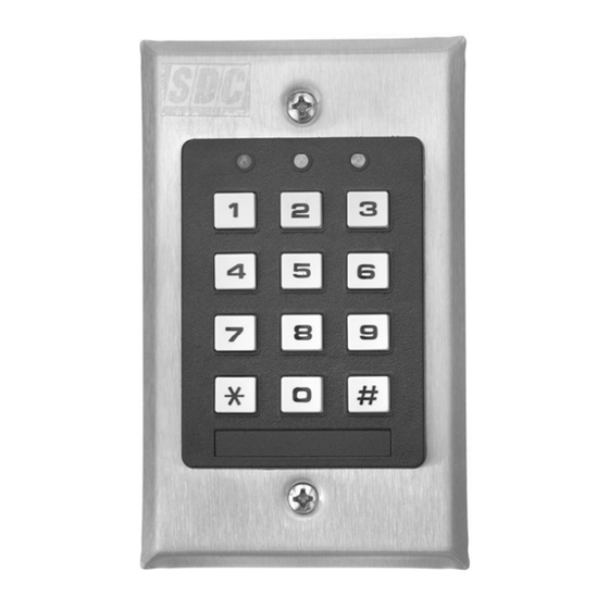
917
Keypad
Electric Locking
Device
Install a diode or MOV to
protect against inductive
kickback.
P:\INSTALLATION INST\ACCESS CONTRLS\INST-917 Stand Alone.vsd
SECURITY DOOR CONTROLS
INSTALLATION INSTRUCTIONS
917 EntryCheck
The SDC 917 Entrycheck Standalone Keypad is designed to control electric locking devices such as
electric door strike, magnetic locks or electrified locksets.
Up to 99 different user codes may be programmed into the 917, making it possible to allow or deny
entry to any one user, without affecting the codes used by the other 98.
Choice of latching or timed output;
Timed output: When an authorized PIN code is entered, the relay is activated, unlocking the door per
programmed time from 1 to 999 seconds. A momentary dry contact connected to the (EG) Request-to-
Exit input activates the timed output. PIN codes will not activate the latching function when the keypad
is programmed for timed operation.
Latching Output: Entering an authorized PIN codes latches the relay output ON or OFF.
A momentary dry contact connected to the (EG) Request-to-Exit input will also activate the latching
output. The lock is maintained in the ON or OFF mode until a PIN code is re-entered or (EG)
Request-to-Exit input is actuated. PIN codes will not activate timed output when the keypad is
programmed for latching operation.
Request-To-Exit Input: A Request-to-Exit device with a momentary, N/O dry contact can be used for
timed egress operation without entering an access code. The device may be an Exit Switch, Sense Bar
or Request-to-Exit PIR sensor and is typically located within the secured area. When latching operation
is chosen, a maintained or momentary, N/O dry contact switching device located remotely or adjacent to
the door may be used for ON/OFF latching without entering an access code.
12-24V AC/DC: Connect 12 or 24V (AC or DC, 50 or 60Hz) to these two terminals to provide the power
necessary to operate the keypad. For most installations, the keypad and electric lock will share the
same power supply.
Output 1: Electric locking device control relay (3 terminals). Connect the positive (+) lead from the
power supply that is being used to power the locking device to the (COM) terminal. If the locking device
is a Fail Safe (power to lock) type, connect the positive lead of the locking device to the Normally
Closed (N.C.) terminal. If the locking device is a Fail Secure (power to unlock) type, connect the
positive lead of the locking device to the Normally Open (N.O.) terminal. Connect the negative wire of
the locking device to the negative (-) lead of the power supply that is being used to power the locking
device
EG.: This terminal is for connection to an Request-To-Exit Egress device. Connect one lead from the
egress button to the EG terminal, and the other lead to the negative power supply output that is
powering the keypad. The egress device must provide a N/O momentary contact. Multiple devices can
be wired in parallel.
Tamper N.C.: These terminals are not used.
Inductive Kickback Protection: Inductive Kickback is a strong electric pulse (up to 500v) generated
by electric locks when power is removed. It is strong enough to destroy the relay contacts in the 917
keypad, unless a protective device is added to the circuit. Included with the 917 keypad is a diode that
can provide this protection for DC-powered electric locks (except magnetic locks). For magnetic locks
and all AC-powered locks, use an MOV instead. Wire it into the circuit as seen in the diagram to the
left, taking note of the polarity for the diode (identified by the silver band) and locating it as close as
possible to the electric lock.
Rev G
Stand-Alone Keypad
TM
Features
Installation
03-10
Page 1
Advertisement
Table of Contents

Related Manuals for SDC 917 EntryCheck


Summary of Contents for SDC 917 EntryCheck
- Page 1 Stand-Alone Keypad Features The SDC 917 Entrycheck Standalone Keypad is designed to control electric locking devices such as electric door strike, magnetic locks or electrified locksets. Up to 99 different user codes may be programmed into the 917, making it possible to allow or deny entry to any one user, without affecting the codes used by the other 98.
- Page 2 SDC 491 or 492 Blue Emergency Release Stations. Local Code Criteria per Code Section Sensor with adjustable timer. SDC 14-2 or 492 7 Day Timer, Scheduled Daily Locking/ Titled “Access Controlled Egress SDC 10TD Mini Timer Module for REX Unlocking Doors”...
- Page 3 Programming All program settings are protected by a Master Code, to prevent unauthorized changes. When setting up the 917 keypad for the first time (or if the Master Code has been lost) the first step is to program the Master Code you’d like to use. Master Code, Initial Setup: 1) Disconnect power from the keypad.
-
Page 4: Specifications
User Operation The yellow LED will flash to indicate that the 917 is ready to accept a command. To release the lock, simply enter one of the User Codes programmed into the keypad, followed by the pound symbol (#): UUUU # Where “UUUU”... - Page 5 Example #4 This example uses two 917 keypads to operate the same electric locking device. 917 #1 is considered the master unit and should be located within in the secured area. 917 #2 is the considered a remote egress device and is connected remote egress device terminal (EG) of the master unit.
Need help?
Do you have a question about the 917 EntryCheck and is the answer not in the manual?
Questions and answers