Table of Contents
Advertisement
Advertisement
Chapters
Table of Contents

Related Manuals for Generex CS121L


Summary of Contents for Generex CS121L
- Page 1 Version: 2011-06-23 UPS WEB/SNMP MANAGER CS121 Series User Manual – English...
- Page 3 Generex. It is agreed that all rights, title and interest in the Generex’s trademarks or trade names (whether or not registered) or goodwill from time to time of Generex or in any intellectual property right including without limitation any copyright, patents relating to the Products, shall remain the exclusive property of Generex.
-
Page 4: English Manual
English Manual Dieses Handbuch ist auch in Deutsch verfügbar! Eine aktuelle Kopie erhalten Sie unter download bei www.generex.de. This manual is also available in German! To obtain an actual copy please see the download-page of www.generex.de... -
Page 5: Table Of Contents
Contents English Manual The CS121 family - Introduction About your CS121 1.1.1 General information 1.1.2 Functionalities of your CS121 About the communication with the CS121-Adapter The CS121 Adapter Package Comparison CS121 overview A typical installation - CS121 in a network environment Connect your CS121 ... - Page 6 3.2.10.8 Wake on LAN (WOL) 3.2.11 Scheduled Actions 3.2.12 SNMP 3.2.13 COM2 & AUX 3.2.13.1 COM2 3.2.13.2 AUX and SITESWITCH4 Settings 3.2.14 SENSORMANAGER 3.2.15 RAS Configuration 3.2.16 Save Configuration / Reboot Reading the Logfiles CS121 for Transfer Switches Adapter Software-Updates (Firmware) Firmwareupdate via Setup-tool Firmwareupdate via FTP Firmware flash renewal and recovery...
- Page 7 D.4. MODBUS Modes in the CS121 M (ASCII and RTU) D.5. UPS Parameter D.6. UPSMAN Status Bytes - Standard Device Status Bits D.7. Bus termination D.8. Configuration D.9. TCP/IP - UDP Ports D.10. MODBUS Cables Available Variables of the CS121 Pin layout of Input-sockets of the SENSORMANAGER unit Events/Alarms of the CS121 –...
-
Page 8: The Cs121 Family - Introduction
SNMP Adapter CS121/CS121 Slot: The SNMP adapter is a compact unit requiring minimal workspace (ca. 28x69x126 mm for the external adapter CS121L). The slot card versions of the adapter (CS111 and CS121SC) get inserted into the extension slots of UPS models supporting its card type. - Page 9 functions. The MODBUS-version uses the COM2 as RS485 and is not available for configuration. The MODBUS version can be configured only via Webbrowser, Telnet and Default IP address. SNMP-Traps for remote monitoring and pre-alarming: The main function of the SNMP- adapter lays in the transmission of alarm conditions of the UPS to the monitoring station (SNMP traps and RCCMD traps/commands).
-
Page 10: About The Communication With The Cs121-Adapter
For additional information about MIB and NMS see also the section “UNMS” later on in this manual. For the CS121-SNMP MIB Implementation, please refer to the GENEREX download-page http://www.generex.de/e/download/cs12x/download_p.html This MIB is specially designed for the CS121 and includes SNMP values for all CS121 optional products (Temperature, humidity, alarm contacts, etc.) Basicly this RFC1628CS121.MIB is the... - Page 11 CS121SC User manual English. Configuration cable for serial port configuration (Slot Chinese) via Terminal software - and for connection of optional devices for your CS121. CS121F User manual English. Configurationcable for serial port configuration (Slot FUJI) via Terminalsoftware - and for connection of optional devices for your CS121.
-
Page 12: Comparison
FEATURES and Supported CS121 COMMON FEATURES FOR ALL MODELS OPTIONS UPS models MODELS * CS121L Second mini din 9 All 1400 UPS All CS121 devices are capable of managing external COM port for models from the UPS models for which they are compatible RS232. -
Page 13: Cs121 Overview
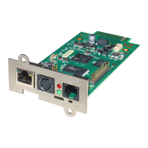
CS121 overview For CS121L, C and Slot card types Description Network connection RJ45 10/100 Base T Connector (with Status LED, green=link, yellow=activity) Serial com-port (COM2) for configuration or connection of optional devices. (not BUDGET versions) Error/Link LED UPS Status (Red=boot or... -
Page 14: Figure 2: Dip-Switches: Cs121L (Left) In Configuration Mode (Ip 10.10.10.10)
UPS communication lost red constantly (3) DIP-Switches: The DIP-Switches differentiate between two functions: Configuration- and normal mode. Figure 2: DIP-Switches: CS121L (left) in configuration mode (IP 10.10.10.10) and CS121SC (right) in normal mode Switch 1 Switch 2 Description Normal operation, device runs on the configured IP-address... -
Page 15: A Typical Installation - Cs121 In A Network Environment
A typical installation - CS121 in a network environment A typical installation on the SNMP-adapter monitoring a UPS in an Ethernet network follows in the illustration below. The SNMP-adapter communicates with the UPS to inform you about your systems power condition. Figure 3: CS121 in a network environment Connect your CS121 ... -
Page 16: Via Lan
CS121 MINI/CS121 R_II: It is required, that the DIP Switch 2 remains in position OFF, otherwise the device will not start (valid for CS121Minislot/CS125/CS121R_II built 2008- 2010 from serial number 0123M-0001 to 0123M-1135). Configuration cable (not CS121BL/BSC): Your package contains a configuration cable, which connects to the serial port (COM2) of the SNMP-adapter and the serial port of a PC with terminal software. -
Page 17: Quickstart
Quickstart The Quickstart manual gives you a short instruction into the main features and how to make some basic settings and guides you in connecting the SNMP-adapter to the network and UPS. Note: Before you start to configure the CS121 please ensure that your connections are valid as described in section 1.8 Verifying the CS121 connectivity (Red network-LED off;... -
Page 18: Establishment Of A Static Cs121 Ip Address Manually
2.1.2 Establishment of a static CS121 IP address manually (default delivery state) The minimum requirement to operate the SNMP-adapter is to set the IP address, subnet mask and the UPS model: The DIP-switches of the SNMP-adapter firstly need to be set for the configuration. DIP- switch 1 is switched OFF in the top position as well as DIP switch 2 is switched OFF. -
Page 19: Using Telnet / Ms-Hyperterminal
Call Configuration, “UPS Model & System” and choose your UPS Model from the drop down list. Further configurations like Power, baud rate, cable type etc. were made automatically (ensure your Browser has enabled JavaScript) and do not need to be set. We strongly recommend to keep the default settings for this UPS unless you have instructions from the UPS maker. -
Page 20: Main Menu & Ip-Settings
Adapter Baud rate 9600 Data bits Parity None Stop Bits Flow Control None Xon/Xoff Handshaking None CR/LF Local Echo Terminal Type ANSI (VT100) Figure 7: Terminal communication settings Please confirm this window with OK when you have done all settings. The Terminal is now ready for communication with the SNMP-adapter and the main menu will start after the password has been entered. -
Page 21: Ups Settings
Figure 9: Telnet - IP Settings To change values, enter the number of the option, type <space> and enter the name. Press <enter>. Your new value displays next to the field heading on the top of the screen. If you want to return to the main menu, press 0 (zero) and <enter>. -
Page 22: Save Configuration
Figure 10: Telnet - UPS Settings The CS121-adapter distinguishes here generally between Cable- and Serial-models. With Cable, the adapter and the contact interface of the UPS are connected with a special cable. Using Serial, UPS models connect to the adapter via the serial UPS-cable. (Part of the UPS package). -
Page 23: Adapter-Restart And Boot Procedure
too early it may corrupt the upsman.cfg configuration file. (see also section 4 Adapter Software-Updates (Firmware)) Note: Various options and settings for UPS-configuration can be done under Telnet or HyperTerminal, e.g. setting access controls of the SNMP- communities, set traps, set display settings, etc. However, the configuration via Webbrowser offers a much more convenient way to configure the CS121. -
Page 24: Quickguide To Install An Rccmd-Job
The event “Powerfail” will be released when the UPS has lost the power supply. This event is usually used to proceed operations like backup-strategies, batch-files to be executed on client stations etc. pp. You can configure such jobs with the “Remaining time”-parameter to ensure the actions will be executed completely. -
Page 25: Figure 12: Http - Job Editor - Introduction
Figure 12: HTTP – Job Editor – Introduction See the figure above, how to configure the RCCMD shutdown for a Client-Workstation. Note, that you enter the correct IP-Address of the Client. Now the RCCMD shutdown procedure is already completed. Press the “Test”-Option in the Event Editor to verify your settings. -
Page 26: Configuration Of The Cs121
Configuration of the CS121 Note: After you have finished the basic network configuration you should have set DIP-switch 1 in position ON and rebooted the adapter. At the SC slot cards you have to remove the card from its slot and change the DIP Switch 1 to position ON. -
Page 27: Configuration
Figure 15: HTTP - UPS Functions AUX & SensorMan Status: The AUX & TEMPMAN status shows the actual measurements of the connected environmental sensor devices SM_T_COM, SENSORMANAGER or TEMPMAN. Figure 16: HTTP - AUX & SensorMan Status In the above figure, a button menu is presented in which the ports 1 and 2 can be clicked on and off. -
Page 28: Figure 17: Http - Ups Model & System
Figure 17: HTTP - UPS Model & System With the parameters UPS ID, system-name, -location, -contact you can describe the UPS and CS121. This is useful e.g. to locate the UPS physically and can be used among others for event settings. Note: Do not change the default UPS-Parameters for Baud Rate and Hold time unless you have special instructions from the UPS maker. -
Page 29: Network & Security
3.2.2 Network & Security Figure 18: HTTP - Network & Security Settings This menu configures the CS121 network card settings, passwords and enable/disables several adapter and network services. We recommend to set the Network Card Speed NOT to “Auto”, but Note: rather to the accordant speed of your switch. -
Page 30: The Cs121 With Dhcp Utilization
use a CS121MODBUS (special hardware) in other cases you have to use MODBUS-over IP. This is enabled by default, you may disable this feature via Telnet or HTML-configuration. Modbus Slave Address: Enter the corresponding number, meaning which number in the chain (bus) the adapter is. -
Page 31: The Cs121 With Icmp Check
Figure 19: HTTP - Network & Security DHCP Settings Click the “Apply” button and reboot the CS121 with the “Save, Exit & Reboot” function. Fallback address: If the DHCP server will not be available, just reboot the CS121 to use the fallback address. -
Page 32: Configuration Static Arp Entries
Figure 21: HTTP – Network & Security Hide HTTP Links 3.2.6 Configuration Static ARP Entries The CS121 firmware version 4.x or higher provides the configuration of static ARP entries into the “Network & Security” menu: Figure 22: HTTP – Network & Security ARP Settings You can determine into the ARP Settings, which IP address to which MAC address will be assigned. - Page 33 Custom test: A custom test checks, if the batteries are able to hold the downtime at least. Full test: A full test is used to calibrate the UPS and will discharge the batteries till the „battery low“ limit. This test should be done once a year at most, because to avoid a damage of the batteries.
-
Page 34: Email
providing this function or are password protected. Activate this function into the BIOS settings of the motherboard. Send Periodic Email: This is a function to send the log files via email periodically (from firmware 4.xx and higher). 3.2.8 Email If you wish to define actions to send Emails depending on specified events you need to configure the Email settings. -
Page 35: Timeserver
PC with an internet clock. How to setup the MS-Timeservice is described below. If you do not have any internet access in your network, you may setup a timeserver which use the PC clock. For this you may choose any freeware from the internet or download from here: http://www.generex.de/wwwfiles/timeserver/atcs22.zip... -
Page 36: Figure 26: Ms-Timeservices
Test Timeserver connection: This option is testing the Timeserver connection with a time and date stamp. Please note that the connection to the timeserver only works, when the adapter is not in the configuration mode (IP 10.10.10.10). The CS121 should have a timeserver to synchronize the UPS alarms with your local time. -
Page 37: Events / Alarms
Figure 27: Registry NTP Server 3.2.10 Events / Alarms The Event/Alarm-pages are the main feature of the CS121-configuration and are based on a combination of events and actions (resp. Jobs). At CS121 there are various events defined, such as e.g. “Powerfail”, “UPS Battery bad”, “Battery low” etc. Each event the CS121-adapter allows you to release one or more actions. -
Page 38: Treshold Events
Choose the event you wish to configure to enter the event editor. Figure 29: HTTP - Event Editor The Event Editor allows you to edit, delete and test existing events, as well as to add a new event job. Please click on the desired action to enter the Job Editor, who lets you make the configuration. -
Page 39: Logfile Entries
Figure 31: HTTP – Treshold event The CS121 firmware version 4.27.x or higher provides the option to configure pre-threshold events for the analog sensor inputs (temperature, humidity etc.) additionally. In this example a pre-threshold alarm for a SM_T_COM temperature sensor for the value temperature low of 13°C and temperature high of 37°C were defined. -
Page 40: Email-Job
Alarmlog-file using a FTP connection with the default IP address 10.10.10.10 or the configured IP-address and the username/password combination “admin/cs121-snmp”. Alternatively the logfiles can also be watched with the GENEREX monitor-tools UPSMON or JAVAMON resp. via the Webbrowser. About the logfiles-contents please see also section 3.3 Reading the Logfile. -
Page 41: Email-To-Sms
Figure 35: HTTP - Job Editor: Continuous event job 3.2.10.4 Email-To-SMS In order to send a SMS message in case of an alarm, you have to use the “Email to SMS Service” of your GSM provider. This is a service where the UPSMAN sends an email to the service center of your GSM provider, who converts the email into an SMS. - Page 42 forward RCCMD signals. For installation of RCCMD at client-side please see the section in chapter “Add-on software”. Note: RCCMD clients are optional and not freeware. Most CS121 are equipped today with a single RCCMD standard license, some UPS makers add more licenses, other do not deliver any license at all with a CS121.
-
Page 43: Figure 36: Http - Job Editor: Rccmd Shutdown
Figure 36: RCCMD SSL Settings The SSL network feature requires correct time settings, so it is required to configure a timeserver. Click the „Timeserver“ configuration button and enter the address of at least one timeserver. Figure 37: Timeserver Settings Click the „Save Configuration“ button and the „Save, Exit & Reboot“ button to confirm your settings. -
Page 44: Figure 37: Http - Event Configuration
Figure 38: Settings Confirmation Start the RCCMD Wizard installation again and enable the SSL network feature. Figure 39: SSL Configuration Figure 40: Advanced Network Settings 3.2.12 RCCMD with own SSL certificates In this chapter we will describe, how to use an own SSL certificate with RCCMD, e. g. OpenSSL ( http://www.openssl.org ): Be your own CA Using OpenSSL it is quite simple to become your own CA. -
Page 45: Figure 40: Http - Job Editor / Function
CA.pl –sign Now create an empty file named “rccmd.pem“ and copy the cert information of newcert.pem (rccmd certificate), newkey.pem (private key) and cacert.pem (CA) into it. Please note, that the exact copying is required to use it without trouble! Use your own RCCMD certificate Do the following steps at the RCCMD Client and every sender (e. -
Page 46: Rccmd Shutdown
Note: All network components, such as routers, hubs etc. need to be fully UPS-supported, as it is otherwise not possible to reach all clients during the network shutdown. 3.2.12.1.1 RCCMD Shutdown Figure 41: HTTP - Job Editor: RCCMD Shutdown Here, IP-addresses from computers with RCCMD connection (receivers) in the network can be entered. -
Page 47: Figure 45: Http - Job Editor Rccmd Wakeup
Figure 42: HTTP – Event Configuration Click the “Add new job” button. Figure 43: HTTP – Event Editor Select the function “Send RCCMD Shutdown to remote client” in the Job Editor: Figure 44: HTTP - Job Editor Enter the ip-address of the client, that should receive the shutdown. Description of the scheduler box : "Immediately, once: Action/Job will be executed in case that this EVENT is true immediately, only once the Action/Job is started (no repeat)". -
Page 48: Figure 47: Http - Job Editor: Rccmd Execute/Command
of x seconds and repeated every x seconds again. "After x seconds”: Action/Job will be executed in case that this EVENT is true after a delay of x seconds. Action will be cancelled, if EVENT is false before time has run out. "After x seconds and repeat”: Action/Job will be executed in case that this EVENT is true after a delay of x seconds and will be repeated after x seconds again. -
Page 49: Automatic Reset Of The Redundancy Alarm
Figure 47: HTTP – Event Editor / Test After you have clicked the “Test” button (Attention! The shutdown will be executed immediately without consideration of the defined delay), the following message will be displayed: Figure 48: HTTP – Job Test Page You can see the successful sending of the signal into the “AlarmLog”: Figure 49: HTTP –... -
Page 50: Rccmd Execute/Command
The parameter „WAKEUP“ got the same function like the „Send RCCMD cancel shutdown“ and resets the redundancy alarm of a RCCMD Client into initial state. For this the events „POWER RESTORED“, „BATTERY LOW OFF“, „UPSMAN STARTED“ and „GENERAL ALARM OFF“ are suitable too, to configure the function „Send RCCMD command to remote client“... -
Page 51: Example Of Use 1: Cs121-Adapter As Rccmd-Listener
Figure 52: HTTP - Job Editor: RCCMD execute/command Any CS121, SITEMANAGER, SITESWITCH can also act as an RCCMD listener; see the following examples: 3.2.12.1.4 Example of use 1: CS121-adapter as RCCMD-listener If it is necessary to execute a command with parameters or a user defined script then these commands must be prepared as an executable batch on the RCCMD client. -
Page 52: Figure 54: Http - Scheduled Actions With Warning
“20000” is the command to switch outputs. (for other commands please contact GENEREX support) Syntax examples: |UPSCMD|20000|1,1 = Output 1 on |UPSCMD|20000|1,0 = Output 1 off |UPSCMD|20000|2,1 = Output 2 on |UPSCMD|20000|8,0 = Output 8 off Figure 54: HTTP - Job Editor: RCCMD-Command If you want to send a signal from a RCCMD client, e.g. -
Page 53: Rccmd Trap
Confirm Analog-Alarm : The way it works with the ACK of analog alarms like Temperature thresholds exceed on the UNMS. Syntax : |UPSCMD|20002|x where x is the Portnr. (1-8). („20002“ is the ACK command for for analog signals) |UPSCMD|20001|4 Syntax example: This command confirms the Analog-Alarm 4 on a SITEMANAGER, SITEMONITOR, SITESWITCH or CS121 AUX Inputs. -
Page 54: Aux-Port
Outputs. For the AUX we provide several “add-ons” like the SS4AUX, SM_IO Relay box, SM_BUZZ Alarm beeper, etc. For a complete overview of “add-ons” for the AUX please see the according datasheet, downloadable from www.generex.de. The CS121 L (external box) allotted from serial number 0121-10417 (delivered from 31.07.2008) about a COM3 port. -
Page 55: Scheduled Actions
3.2.13 Scheduled Actions This menu is for programming schedules actions on your CS121 or facility manager SITEMANAGER. When combined with the other facility managing functions of the CS121 adapter, the Scheduled actions tool can be used to operate and run many different tasks, e.g. Switch on/off UPS, do battery tests, switch to “green mode”... -
Page 56: Com2 & Aux
Please ensure that in the menu “Network & Security” the option “SNMP Note: Agent” is enabled. SNMP Traps have nothing to do with RCCMD traps or the RCCMD shutdown functions. RCCMD works independent from SNMP. The submenu displays a column of 10 manager IP-addresses with the corresponding access permission, the commands and an example. - Page 57 Pipe-Through Mode 1: Enable or disable the “pipe-through” of the adapter. If enabled, the RS-232 protocol of the UPS will be transmitted to the COM2 of the adapter, so now you can connect any other RS-232 software to the adapter to make use of the RS-232 UPS protocol – parallel to the adapter. This makes the use of multiplexer hardware is no longer necessary.
- Page 58 Figure 63: HTTP - COM2 & AUX with TEMPMAN RAS-Mode The selection of the “RAS”-entry in the drop down menu of the COM2 settings enables the CS121-RASManager function. This function is only operational if a RASMANAGER ist used (CS121 with inbuilt modem) and a RASMANAGER license key is provided (optional, part of RASMANAGER).
-
Page 59: Aux And Siteswitch4 Settings
SM_T_H_COM The SM_T_H_COM is a temperature and humidity sensor for the CS121 and is used for the monitoring and controlling of UPS rooms, server rooms etc.. Please take a look into the SM_T_H_COM datasheet for further information. 3.2.15.2 AUX and SITESWITCH4 Settings The AUX connection is an input/output port for connecting external contact devices such as alarms or for connecting to an SS4AUX SiteSwitch power socket manager. -
Page 60: Ras Configuration
Within the configuration page “Sensor Manager Settings” of the CS121 you can - among others - define limit values when events (to be configurated in “Events / Alarms”) will be released. Figure 64: HTTP – Sensor Manager Settings Please see SensorMan in section “Accessories” of this manual. 3.2.17 RAS Configuration This is the standard setting for the RASManager, the CS121 with the built-in modem. -
Page 61: Save Configuration / Reboot
3.2.18 Save Configuration / Reboot If you are satisfied with your configuration select “Save, Exit & Reboot” and wait until the adapter informs you about the reboot-process. Please notice that a reboot of the CS121 may take up to 3 minutes. During the boot phase the CS121 is compiling the user settings and waits for timeserver response. - Page 62 01/17/2007,16:35:51,MAIL: subject "CS121 Event 44" successfully sent 01/17/2007,16:35:57,MAIL: subject "CS121 Event 45" successfully sent These are 8 Emails sending information about analogue sensors (temperature, humidity and the like) that are connected to a SENSORMANAGER, indicating that all controlled values are within tolerance levels - or that no sensor is connected to the device or connection port.
- Page 63 Figure 67: HTTP – CS121 ExternalDeviceLog In figure 62 the logging of a SM_T_H_COM is displayed, sensor 1 for the temperature, sensor 2 for the humidity. At unify UPS their events will be imported out of the UPS directly and are displayed into the CS121 menu LogFiles, “UPS Events”.
-
Page 64: Cs121 For Transfer Switches
CS121 for Transfer Switches The CS121 is used from time to time for automatic transfer switches (ATS) too. The graphical display depends on the manufacturer. Figure 69: HTTP – Status Page Socomec Transfer Switch Figure 70: HTTP – Status Page Eaton Transfer Switch... -
Page 65: Adapter Software-Updates (Firmware)
There are two ways to update your firmware-version, by using the Setup-tool or via FTP. Firmwareupdate via Setup-tool Firmware updates are available for free at www.generex.de. Download the specified version (mind your OEM ID) and follow up the setup-procedure. If necessary, consult your UPS dealer for further information. -
Page 66: Firmware Flash Renewal And Recovery
and reboot the adapter. Afterwards, reconfigure the device via Telnet. For more details read the README.TXT of the firmware update package. Note: The configuration of the CS121 can be saved for archiving purposes using an ftp-connection. Simply download the „upsman.cfg“ to the directory of your choice. -
Page 67: How To Get The "Upsman.cfg" From A Cs121 To Your Computer Via Ftp
1. Before starting the update, unplug the adapter from the power supply (slot cards have to be removed from the slot). 2. Set a route to default IP-Address. Command syntax on your windows computer: "route add 10.10.10.10 <your IP address>". Also note that the flash tool can also be used to set the route for you by checking the set route check box in the update interface. - Page 68 Figure 73: CS121-Configuration Manager Via FTP: Enter the following into the address field of a web-browser: ftp://<ip-address of your CS121>. Enter the username admin and the password cs121-snmp. You will find the „upsman.cfg“ into the „flash“ folder. Figure 74: CS121-FTP Access...
- Page 69 Figure 75: CS121-FTP Context Menu Figure 76: CS121-FTP Folders...
- Page 70 Figure 77: CS121-FTP Upsman.cfg After you have updated your CS121, please open the „new“ and the stored „upsman.cfg“ in an editor. Now check, if the parameter of the new data are present into the stored data. If not, you need to copy the missing parameter of the new data into the stored „upsman.cfg“. Now you can overwrite the „upsman.cfg“...
-
Page 71: Changing The Adapter's Mac-Address
192.168.202.123 4000 Connecting to target 192.168.202.123...ok. 192.168.202.123:/> 4. Enter in the prompt the command: "set MAC <GENEREX MAC Identifier>" <ENTER> Finish. After this you can enter exit and reboot your CS121. GENEREX MAC Identifier - Address code: The GENEREX MAC address range is :... - Page 72 BACS, SiteMonitor, SiteManager: 00-03-05-0A-xx-xx where XX-XX represents the HEX code of the GENEREX CS121 Board’s serialnumber (decimal). How to find the CS121 board serialnumber: Note: This is not the serial number of the CS121 itself, its the serial number of the CS121.
-
Page 73: Additional Software
Please start the installation of the RCCMD-client with the download of the latest version from www.generex.de. (If included, use also the CD from the adapter package) Uncompress the files, execute setup.exe and a wizard guides you through the installation. (Note: Some older versions (using InstallShield5) sometimes stop the installation process with a window, which shows you a completion of 99%. - Page 74 Figure 81: RCCMD Client Installation – IP-Address The following window gives you the possibility to enable a periodical connection check and to attach a batch-file to be executed in the case of a failure. Figure 82: RCCMD Client Installation – Connection check With the following window you complete the installation by attaching batch-files to each action the RCCMD-client can receive from the CS121-adapter.
-
Page 75: Rccmd With Ssl For Windows
5.1.2 RCCMD with SSL for Windows The Secure Sockets Layer (SSL) protocol is a cryptographic protocol that provides security and data integrity for communications over TCP/IP networks. Use your Web-browser to navigate to the address of your UPS Web-Manager. Click the “Network &... - Page 76 Figure 86: Settings Confirmation Start the RCCMD Wizard installation again and enable the SSL network feature. Figure 87: SSL Configuration Figure 88: Advanced Network Settings...
-
Page 77: Rccmd With Own Ssl Certificates
5.1.3 RCCMD with own SSL certificates In this chapter we will describe, how to use an own SSL certificate with RCCMD, e. g. OpenSSL ( http://www.openssl.org Be your own CA Using OpenSSL it is quite simple to become your own CA. Just run: CA.pl –newca Done! Just ensure, that you select a useful CN (common name)! Create your RCCMD certificate... -
Page 78: Rccmd Client As Relay Station
(only older firmware before 4.26) gChart is a GENEREX plug-in for the MS Internet Explorer available as a free download from the GENEREX web site. Quickly and easily visualise all of the CS121-adapter logfiles using Generex's ActiveX graphical log controller GChart when using the Internet Explorer. - Page 79 Figure 90: gchart plug-in for the internet explorer Get the gChart experience now by visiting our online CS121 at: http://q01.generex.de/ and be sure to follow the GChart logfile links. In order to activate this function, the following adjustments in the Internet Explorer Options are required: Click via the menu „Tools“...
-
Page 80: Ups Monitor (Upsmon)
Close the opened windows via „Close“ and „Ok“. Click into the Internet Options and Security again. Click via „Custom level...“ into the Security Settings of the Trusted Sites Zone. Figure 92: Security Settings Activate the following options: Allow previously unused ActiveX controls to run without prompt Download unsigned ActiveX controls Initialize and script ActiveX controls not marked as save for scripting Run ActiveX controls and plug-ins... - Page 81 block diagrams. Other devices, such as diesel generators or extra measuring units can be integrated with this management software via the network. A separate password protected screen can be created, if the devices also support remote controlling commands. The values and status information, which are stored in the UPSMAN log file, can be requested from every computer with an installed UPS monitor module.
-
Page 82: Cs121-Enhancements, Field Of Applications
CS121-Enhancements, Field of applications SiteSwitch4 (SS4) and SiteSwitch4AUX (SS4AUX) Figure 93: SideSwitch4 and SS4 AUX SITEWITCH4AUX is a high-performed extension of the CS121-adapter but can also be operated as stand-alone solution with the possibility to connect to UPS or UPS-similar devices. The SITESWITCH has 4 power outputs sockets, which can be configurated by the event settings of the CS121 or any other RCCMD compliant sender like SITEMANAGER, SITEMONITOR. -
Page 83: Ss4 Feature Overview
Check http://www.generex.de for manual updates. 6.1.3 SS4 Installation The power consuming devices are connected to the SS4 using IEC 250 VAC/6A plug cables. The SS4 has 4 IEC 250VAC/6A chassis sockets that can be switched on and off separately. -
Page 84: Ss4 - Technical Data
0-40°C/rel.Humidity0-95% non condensating Sensor SM_T_COM The SM_T_COM is a temperature sensor for the use with a GENEREX CS121. It has a range from -25° - 100° Celsisus (-13° –212° Fahrenheit) and comes with a 1.8 meter cable for connecting to the CS121 COM2 port. The SM_T_COM is designed for monitoring and management of 19"- racks, UPS rooms, server and data center rooms and for industrial... -
Page 85: Sm_T_Com Configuration
6.2.1 SM_T_COM configuration Figure 98: CS121- SM_T_COM Settings Enter the desired values for the Threshold (low) and Treshold (high). You can calibrate every sensor with the Offset, that means if you want to rise a measured value for 5°C, just modify the default range from 0.0 to 5.0. Therefore you are able to adjust the measurement values like a gauged thermometer. -
Page 86: Sensormanager & Sensormanager
Figure 101: CS121-Configuration Threshold Event for SM_analogue 1 SENSORMANAGER & SENSORMANAGER II 6.3.1 General information If more than 1 or 2 environmental values are wanted to manage, than the SENSORMANGER (SensorMan) is your choice. This device is a data measurement and collecting unit which allows the individual measurement and monitoring of 8 analog measurement devices (0-10V) and 4 digital alarm inputs or 4 outputs (open collectors). -
Page 87: Installation And Network Integration
RS-232 protocol for the SENSOR MANAGER from our website and adjust your software to this communication type. Important: New firmware for your CS121 is available for download at: http://www.generex.de 6.3.2 Installation and Network integration Figure 103: CS121-Installation with SENSORMANAGER As shown in the figure above CS121 can also be applied to observe and react on alarms of the SENSORMANAGER-Inputs. - Page 88 all 8 analog inputs, you have to use a splitting plug (optional) or connect the sensors directly to the Channel Inputs as described above. If you use the sensor type SM, you may connect a second SM sensor to the input of the first SM.
- Page 89 TEMPMAN/SENSOR MANAGER and how to manage and set the alarms. The latest version of CS121 user manual is available for download at: http://www.generex.de/wwwfiles/dokus/1/cs121/german/pdf/cs121.pdf When the SENSOR MANAGER is running, you will see the values in the AUX section of the CS121 Web browser.
-
Page 90: Special Features Of Thesensormananager Ii
INPUT 3: Pin 1 Voltage 9-24Volt + Pin 2 Analog Channel 3 (0-10V+) Pin 3 Analog Channel 7 (0-10V+) Pin 4 Ground Pin 5 OUTPUT: Open collector OUT 9-24 V, max. 30mA Pin 6 INPUT: Digital Input 9-24V INPUT 4: Pin 1 Voltage 9-24 Volt + Pin 2... -
Page 91: Configuration
Figure 106: SENSORMANAGER II Status Site 6.3.4 Configuration The SENSORMANAGER II provides the opportunity of the definition of pre-alarm-thresholds. Beside the name of the input you also define here as shown above the alarm thresholds, the sensor range and the measurement unit. Note, that the alarm values (low and high) are only active if the fields beside the alarm values are enabled. -
Page 92: Alarm Matrix Of The Sensormanager Ii
Figure 108: SENSORMANAGER II Configuration Outlets Furthermore it is possible to attach a timer value to each Outlet. This determinates how long an outlet will be switched (in seconds). Set the timer value to “0” if the outlet is to be switched without any time limit. -
Page 93: Rasmanager
in chapter 3.2.5 Events / Alarms. This is possible because each marker has its own event “Alarm Marker x”, which can be configured through the event configuration. The second possibility is to switch a relay output in dependency of the statue of one or several markers. -
Page 94: Gsm Modem - Notification Via Sms
The CS121 firmware version 4.17.x provides a new function, which enables the notification via SMS. Use the CS121configuration cable and an adapter-connector (PINs 2, 3, 5, GENEREX order number: GSM_A) for the connection of the GSM modem and the CS121. Select into the menu “COM2 &... - Page 95 Figure 114: Mini8-DSUB9 Cable Cross-Section Figure 115: COM2 Mode: GSM Modem Add an accordant function via the “Events / Alarms” menu. Select the function “Send SMS with GSM modem” for the notification via SMS and set the telephone number of the receiver and the message.
-
Page 96: Led-Matrix Display
SIM card not present Slowly red flashing SIM card active Fast red flashing Figure 117: Siemens GSM TMA T35i Modem Into the menu “System & Network Status” you can see the signal level of the modem, to adjust your antenna optimal. Green means a good signal is present. Figure 118: GSM Signal Quality Display LED-Matrix Display The LED-Matrix display is a remote display unit for relaying RCCMD messages that can be... -
Page 97: Modbus / Profibus
To integrate the CS121 in a Profibus environment, GENEREX offers a Profibus gateway, which converts the MODBUS output of the CS121 into PROFIBUS environment. The implementation of LONBUS or any other GENEREX field bus converter takes place in similar way. -
Page 98: Unms (Ups-Network Management System)
Figure 121: CS121 PROFIBUS Installation UNMS (UPS-Network Management System) UNMS II is a UPS network monitor designed to inform you of emergency power supply systems problems before your clients, end-users or managers do. The UNMS as a limited version is part of every UPSMAN license (UPSMAN suite contains UPSMAN RS232/USB UPS Manager, UPSMON Windows client and UNMS 2 –... - Page 99 MIB-Integration into your NMS Standard-NMS Installations require for each device to be monitored its specific MIB (Management Information Base). To monitore the CS121 the Standard-MIB for UPS-systems, RFC1628, is generally to be integrated into your NMS. To identify CS121 adapters in your network you may use the MAC address. The MAC address of every CS121 adapter starts with 00-03-05-02-XX-XX, whereas this address can be found in the Telnet menu (menu: IP address, gateway address, MIB system group).
-
Page 100: Troubleshooting - Faq
Note: SNMP response changed: Now only those SNMP requests are answered, which are present at this UPS or other device. Missing data does no longer cause a return value "0" or "-1". An SNMP Walk will now no longer return any OIDs, which are not supported by this UPS. Troubleshooting –... - Page 101 Figure 125: CS121 Network Card Speed Configuration Problem: No communication possible to APC UPS SURTD from 2011 Solution: This UPS model communicates with a proprietary protocol. It is required to use the APC slot card Legacy (AP9620) for the establishment of a communication.
-
Page 102: Appendix
US and Canada with the power supply 12 V DC, 300 mA. As well, for both hardware specifications 121 and 131 of CS121-Adapter a certification of Conformity has been drawn up. Please see the download page at www.generex.de to get a copy of the certifications and documents. - Page 103 Figure 126: Cable configuration HW121 COM2 CS121 HW121/HW131 configuration cable with handshake Figure 127: Cable configuration HW121/HW131 COM2 Pin Layout CS121 COM1: Figure 128: External D-SUB 9-polig male Pin1: Pin6: Pin2: Pin7: Pin3 Pin8: Pin4 Pin9: Pin5...
- Page 104 Figure 129: Slot version: Circuit board connection Pin1: -> GND Pin2: -> VDD Pin3: -> TxD Pin4: -> RxD Pin9: -> GND Pin8 connected with Pin 10 Figure 130: Pin COM2 Mini-DIN 8 pol female Mini DIN 8 socket RS-232: Pin1: ->...
- Page 105 Pin1: -> +3,3V Pin2: -> Input/Output 1 Pin3: -> Input/Output 2 Pin4: -> Input/Output 3 Pin5: -> Input/Output 4 Pin6: -> GND The maximum input voltage is 3,3V. The input signals may be fed from external power sources or feed directly from Pin 1. If the external power supply delivers more than 3,3V a pre-resistor has to be fitted.
-
Page 106: Modbus Interface
Figure 135: Examples: AUX Input on hardware model CS131 only, left side “pull-down”, right side “pull-up” configuration Figure 136: AUX Port Assignment AUX port assignment for CS121 HW131 L from serial number 0121-10417 and CS121 HW131 SC from serial number 0123-09428: PIN 1: 3,3V PIN 2: AUX port 0: disposable PIN 3: AUX port 1: disposable... -
Page 107: Available Modbus Function Codes
recommend for ASCII the use of 7/N/2 and the highest baudrate supported by your device. RTU Mode works at CS131 & CS121 platforms with communcation parameters 8/E/1 or 8/N/2 or 8/N/1 or 8/E/2 or 8/O/2 or with 8/O/1 from baudrate 1200 to 38400. We recommend for RTU the use of 8/E/1 and the highest baudrate supported by your device. -
Page 108: Modbus Modes In The Cs121 M (Ascii And Rtu)
If the slave device receives the query without a communication error, and can handle the query normally, it returns a normal response. If the slave does not receive the query due to a communication error, no response is returned. The master program will eventually process a timeout condition for the query. If the slave receives the query, but detects a communication error parity, LRC, or CRC, no response is returned. -
Page 109: Ups Parameter
ning number code count s of the e return feed colon word high byte byte ASCII : <CR> <LF> [3A] [30][31] [30][34] [30][32] [31][32] [33][34] [42][33] [0D] [0A] ASCII: Data, which will send over the link as ASCII characters. HEX: Hexadecimal values of the data ... - Page 110 STATUS (e. g. UPS normal = “4”, 3 / 4 UPS Status (ASCII HEX) Powerfail = “12”, Battery test Please note UPSMAN running = “68”, Bypass = “5” ) status bytes table below 3 / 4 BATTVOLT Battery Voltage V 3 / 4 INFREQ0 Input Frequency Hz Phase...
- Page 111 Section OEM NEWAVE UPS Timesyncronization signal Command 16 (write) : When this signal is set, the CS121 sets the internal clock to 01:00 of the same day. Command 3 or 4 (read) is not allowed. 3 / 4 Manual Bypass Switch Closed 0 = open 1 = closed 3 / 4...
- Page 112 Section OEM MASTERGUARD 3 / 4 PXWARN 3 / 4 FAULT CODE 1 3 / 4 FAULT CODE 2 3 / 4 FAULT CODE 3 3 / 4 FAULT CODE 4 3 / 4 BADBATTBLOCK 1 3 / 4 BADBATTBLOCK 1 3 / 4 BADBATTBLOCK 1 3 / 4...
- Page 113 word 4 I in S phase 0.1A input current word 4 I in T phase 0.1A input current word 4 F input frequency 0.1Hz word 4 U out R phase 0.1 Volt output voltage word 4 U out S phase 0.1 Volt output voltage word 4...
- Page 114 from CS121 Section OEM Rittal firmware version 4.22.14 3 / 4 Manual Bypass Switch Closed 0 = open 1 = closed 3 / 4 OUTPUT_VOLT0 Outputvoltage Phase 1 3 / 4 OUTPUT_VOLT1 Outputvoltage Phase 2 3 / 4 OUTPUT_VOLT2 Outputvoltage Phase 3 3 / 4 OutputCurrent Phase A * 10 Output Current Phase 1 in...
- Page 115 Section OEM Netminder for all LT and MD types Address Type Function Name Description Length INVOLT Input Voltage OUTPUTVOLT Output Voltage BATTVOLT Battery Voltage OUTPUTCURR Output Current LOADPERC Load (%) OUTPUTPOW Output Power in W FREQUENCY Frequency CS121UPSSTAT CS121 UPS Status Alarm: Battery Bad 1 = active;...
- Page 116 Alarm: Communication Lost 1 = active; 0 = not active Alarm: Awaiting Power 1 = active; 0 = not active Alarm: Shutdown Pending 1 = active; 0 = not active Alarm: Shutdown Imminent 1 = active; 0 = not active Alarm: Test In Progress 1 = active ;...
- Page 117 OUTPUTVOLT Output Voltage (l2-n) OUTPUTVOLT Output Voltage /(l1-l2) OUTPUTCURR Output Current (l1-n) OUTPUTCURR Output Current (l2-n) OUTPUTWAT Output Watts (l1-n) OUTPUTWAT Output Watts (l2-n) OUTPUTWAT Output Watts (l1-l2) OUTPUTWATTOT Output watts (total) OUTPUTVA Output VA (l1-n) OUTPUTVA Output VA (l2-n) OUTPUTVA Output VA (l1-l2) OUTPUTVATOT...
- Page 118 Alarm: UPS Output Off 1 = active; 0 = not active Alarm: UPS System Off 1 = active; 0 = not active Alarm: Fan Failure 1 = active; 0 = not active Alarm: Fuse Failure 1 = active; 0 = not active Alarm: General Fault 1 = active;...
- Page 119 Secti POWERTRONIX MIZAR Adres Name ALCOR QUASAR SUPERNOVAE Outpower Phase 1 % Outpower Phase 2 % Outpower Phase 3 % Battery Capacity % Input Voltage Phase 1 V Input Voltage Phase 2 V Input Voltage Phase 3 V Temperature °C not supported Autonomy Time minutes UPS Status (ASCII Hex)
- Page 120 Alarm: UPS Output Off Alarm: UPS Sytem Off not supported not supported Alarm: Fan Failure supported Alarm: Fuse Failure not supported supported not supported Alarm: General Fault Alarm: Diagnose Test Failed not supported supported not supported Alarm: Communication Lost Alarm: Awaiting Power not supported supported not supported...
-
Page 121: Upsman Status Bytes - Standard Device Status Bits
D.6. UPSMAN Status Bytes - Standard Device Status Bits UPS Status Hex-Value Dec-Value Description UPS_SB_BYPASS_MODE 0x0001 power piped thru UPS_SB_SHUTDOWN 0x0002 shutdown ups UPS_SB_OUTPUT_ACT 0x0004 inverter on = UPS OK UPS_SB_BACKUP_MODE 0x0008 battery power UPS_SB_BATTERY_LOW 0x0010 low battery err UPS_SB_OVER_TEMP 0x0020 over temp err UPS_SB_TEST_ACT... -
Page 122: Configuration
Figure 137: MODBUS - Jumper D.8. Configuration Please use Telnet (network connection) for the configuration with the default IP address 10.10.10.10. Put DIP switch 1 into the “OFF” position. If you have a RS-232/ RS-485 converter available you can also use a HyperTerminal via COM2 with both DIP switches in the “OFF” position. -
Page 123: Available Variables Of The Cs121
Figure 138: MODBUS - Cable 112 NOTE: it is very important that the Shield is connected to the MINI 8 housing and to the MODBUS requesting device common ground! Available Variables of the CS121 Note: Not all variables are supported from all UPS-models. Please try the use of the variable to see, whether your UPS supports the variable or not. -
Page 124: Pin Layout Of Input-Sockets Of The Sensormanager Unit
POWER Configurated UPS Power LOAD Configurated Load HOLDTIME Configurated hold time RECHARGETIME Configurated time for a complete battery charging MODEL UPS model name TIMEREMAIN Resttime (AUTONOMTIME-POWERREMAIN) LOCALTIME Local timestamp OUTPHASES Output phase INPHASES Input phase LOCATION UPS-Adapter location DATE Date TIME Time ATTACHED_DEVICES Attached devices... -
Page 125: Events/Alarms Of The Cs121 - Description Of The Alarms
INPUT 3: Pin 1 Input Voltage 9-24Volt + Pin 2 Analog Channel 3 (0-10V+) Pin 3 Analog Channel 7 (0-10V+) Pin 4 Ground Pin 5 OUTPUT: Open collector OUT 9-24 V, max. 30mA Pin 6 INPUT: Digital Input 9-24V INPUT 4: Pin 1 Input Voltage 9-24 Volt + Pin 2 Analog Channel 4 (0-10V+) Pin 3 Analog Channel 8 (0-10V+) - Page 126 Output Breaker Closed Output breaker closed. Load will be supplied. Maintenance breaker closed (active). Load will be supplied through the Maintenance Breaker Closed grid directly. Maintenance breaker open (inactive). Load will be supplied via the UPS. Maintenance Breaker Open Regular UPS protected operation. Inverter Breaker Open Inverter breaker open.
- Page 127 Battery Depleted Battery depleted Input Bad Input bad, alarm will be triggered with the powerfail event Mains Input Okay Power restored at the input Fan Failure UPS fan failure Fan Ok UPS fan OK Awaiting Power Awaiting power prior of automatic start of UPS Shutdown Pending UPS shutdown/switching off is pending Shutdown Imminent...
-
Page 128: Description Of The Alarms For Single-Phase Ups
Output Normal Output normal, normal condition Redundancy Ok Redundancy is at hand AUX Port 1 High AUX port 1 opened AUX Port 2 High AUX port 2 opened AUX Port 3 High AUX port 3 opened AUX Port 4 High AUX port 4 opened AUX Port 1 Low AUX port 1 closed... - Page 129 This event is TRUE, if the remaining time is reached or rather undershot. That means the autonomy time is only available for seconds, the UPS System Shutdown shutdown is pending. UPS service is started into the CS121. This event is always true, if the CS121 is running and therefore ideal for permanent recurrent jobs suitable like the forwarding of emails always after restart of the UPS or to produce log file UPSMAN started...
- Page 130 AUX Port 3 Low AUX port 3 closed AUX Port 4 Low AUX port 4 closed Configuration of Microsoft SCOM 2007 as CS121 Trap Receiver (Monitor) In this section we will configure Microsoft Operations Manager 2007 (SCOM/OpsMgr) as an SNMP Trap receiver, discover SNMP-enabled cs121 network devices, and configure an alert- generating SNMP-trap-based monitor to raise alerts when specific traps are received from cs121 devices.
- Page 131 OpsMgr server. Alternatively, you could select the Accept SNMP packets from any host option. Restart the SNMP Service. IMPORTANT: SNMP community strings are case sensitive! Activate the SNMP Trap Service (on Windows Server 2003) In the Services Panel, select the SNMP Trap Service In the SNMP Trap Service properties dialog select «...
- Page 132 Figure 142: Select a Monitor Type On the General Properties page, do the following: Type the Monitor name, such as UPS On Battery Monitor. Optionally, type a Description for the monitor. Click Select, select View all targets, click a target, such as SNMP Network Device, and then click OK.
- Page 133 Figure 143: General Properties On the Configure the trap OIDs to collect page for the First SNMP TrapProvider, leave Use discovery community string selected. Click to place the cursor in the Object Identifier Properties section and type the first object identifier (OID) that you want to monitor: 1.3.6.1.2.1.33.2.3 (upsTrapAlarmEntryAdded).
- Page 134 Figure 144: Configure the trap OIDs to collect On the Build Event Expression page, click to place the cursor in the Parameter Name section and type the trap parameter variable that you want to use here: /DataItem/SnmpVarBinds/SnmpVarBind[2]/Value Why did we use SnmpVarBind[2] in our expression? Because the traps second contains the OID of the traps UPS alarm (Object upsAlarmDescr of the trap).
- Page 135 Then click Next. On the Configure the trap OIDs to collect page for the Second SNMP TrapProvider, leave Use discovery community string selected. Click to place the cursor in the Object Identifier Properties section and type the first object identifier (OID) that you want to monitor: 1.3.6.1.2.1.33.2.4 (upsTrapAlarmEntryRemoved).
- Page 136 Figure 147: Build Event Expression Then click Next. On the Configure Health page, select Critical for the Health State of Monitor Condition First Event Raised. Then click Next. Figure 148: Configure Health On the Configure Alerts page, set the properties of the alert, for example: Type the Name for the alert, such as UPS OnBattery Alert.
- Page 137 Figure 149: Configure Alerts Discover your SNMP enabled CS121 devices in OpsMgr In the Administration space, right click and launch the Discovery Wizard. On the What would you like to manage page, select Network Devices. Then click Next.192.168 On the Discovery Method page, enter the Start and End of the IP address range that you want to scan.
- Page 138 Figure 150: Discovery Method Discovery for even a single device will run for a couple of minutes by default. If you specify an IP range, it will take a little longer. On the Select Objects to Manage page, select the devices desired for management. On the Summary page, click Finish.
-
Page 139: Table Of Figures
Table of figures Figure 1: Connectors of the CS121.................. 11 Figure 2: DIP-Switches: CS121L (left) in configuration mode (IP 10.10.10.10) ....12 Figure 3: CS121 in a network environment ..............13 Figure 4: HTTP - Administrator login ................16 Figure 5: HTTP - UPS Model &... - Page 140 Figure 57: Pipe Thru Installation ..................52 Figure 58: HTTP - COM2 & AUX with TEMPMAN ............. 53 HTTP – Sensor Manager Settings ..............55 Figure 59: Figure 60: HTTP - RAS Manager Settings ................ 55 HTTP – CS121 DataLog .................. 57 Figure 61: HTTP –...
- Page 141 Figure 114: LED-Matrix display network integration ............. 92 Figure 115: CS121MODBUS Installation ................92 Figure 116: CS121 PROFIBUS Installation ................93 Figure 117: UNMS-Installation ..................... 93 Figure 118: Mainboard Inform Pyramid DSP ............... 95 Figure 119: CS121 AlarmLog, ProtMan Connection ............95 Figure 120: CS121 Network Card Speed Configuration ............
Need help?
Do you have a question about the CS121L and is the answer not in the manual?
Questions and answers