
Subscribe to Our Youtube Channel
Related Manuals for Generex CS121L


Summary of Contents for Generex CS121L
- Page 1 Version: 2016-07-05 UPS WEB/SNMP MANAGER CS121 Series Additional Components (CS121 Extensions) User Manual – English...
- Page 3 Generex. It is agreed that all rights, title and interest in the Generex’s trademarks or trade names (whether or not registered) or goodwill from time to time of Generex or in any intellectual property right including without limitation any copyright, patents relating to the Products, shall remain the exclusive property of Generex.
-
Page 4: English Manual
English Manual Dieses Handbuch ist auch in Deutsch verfügbar! Eine aktuelle Kopie erhalten Sie unter Download bei www.generex.de. This manual is also available in German! To obtain an actual copy please see the download-page of www.generex.de... -
Page 5: Table Of Contents
Contents English Manual The CS121 Family - Introduction About your CS121 1.1.1 General Information CS121 Device Type Overview Scope of Delivery Functional Overview of the CS121 1.4.1 Functionalities of your CS121 The Communication with the CS121-Adapter CS121 Overview of the Connections and LEDs Quickstart Initial Operation of the CS121 Connect your CS121 ... - Page 6 4.2.16 SENSORMANAGER 4.2.17 RAS Configuration 4.2.18 Scheduled Actions 4.2.19 Save Configuration / Reboot Reading the Logfiles RCCMD 4.4.1 RCCMD Jobs 4.4.2 RCCMD Traps 4.4.3 RCCMD Shutdown 4.4.4 Automatic Reset of the Redundancy Alarm 4.4.5 RCCMD Message 4.4.6 RCCMD Execute/Command Example of use 1: CS121-adapter as RCCMD-listener Example of use 2: CS121-adapter switches an output 4.4.7 UPS shutdown...
- Page 7 CS121 - Technical data CE- and UL-Certification Cable and Circuit board configuration, Pin/AUX-Ports, SensorMan 105 CS121 WDP – Watchdog & Powermanager MODBUS Interface E.1. General information E.2. Available Modbus Function Codes E.3. Exception Codes E.4. MODBUS Modes in the CS121 M (ASCII and RTU) E.5.
-
Page 8: The Cs121 Family - Introduction
The following CS121 device types are available as: external adapter slot card adapter Devices Function Description CS121L SNMP-Adapter external adapter with AC/DC converter power supply CS121SC SNMP-Adapter Slot card adapter for chinese UPS CS121F SNMP-Adapter Slot card adapter for FUJI UPS, Japan... - Page 9 CS121 FEATURES and Supported CS121 COMMON FEATURES FOR ALL MODELS OPTIONS UPS models MODELS * CS121L Second mini din 9 All 1400 UPS All these CS121 external COM port for models from devices are capable of managing the RS232. AUX port...
-
Page 10: Scope Of Delivery
External User Configuratio Mini-8 COM Mini-8 COM power manual on n cable port port supply (MODBUS (MODBUS via RS232) via RS485) CS121L (External) CS121SC (Slot Chinese) CS121SCM (Slot Chinese) CS121F (Slot FUJI) CS121R (Slot RIELLO/AROS) CS121LM (Extern) CS121BL (Budget Extern) - Page 11 Functional Overview of the CS121 Professional Functional Overview of the CS121 Budget Functional Overview of the CS121 MINI...
-
Page 12: Functionalities Of Your Cs121
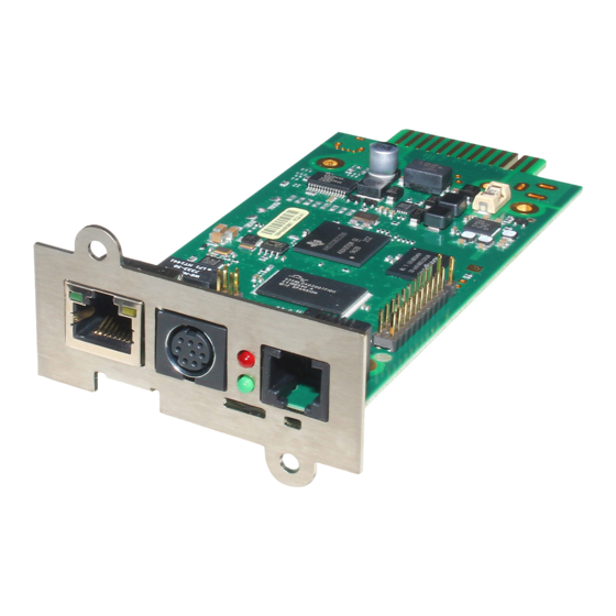
SNMP Adapter CS121/CS121 Slot: The SNMP adapter is a compact unit requiring minimal workspace (ca. 28x69x126 mm for the external adapter CS121L). The slot card versions of the adapter get inserted into the extension slots of UPS models supporting such a card type. -
Page 13: The Communication With The Cs121-Adapter
the remote shutdown of practically an unlimited number of client computers, independent of the operating systems of the clients. RCCMD is an optional part of the UPS-Management Software. Your UPS dealer is able to provide you with license keys for the RCCMD Software. The UPSMAN service of the UPS-Management Software Suite is an optional module and not required for that basic CS121 operations. -
Page 14: Cs121 Overview Of The Connections And Leds
“UPS-MIB”). If you want to include your CS121 to a SNMP-Management station, which does not have the standard MIB RFC1628, you can download the specific MIB from our website http://www.generex.de/e/download/cs12x/download_p.html. Copy the MIB file to the appropriate MIB-directory of your SNMP-station and compile this file. In most cases your SNMP already has implemented this MIB and a compilation is only necessary, if you want to read extra information than just UPS (e.g. -
Page 15: Figure 3: Cs121L (Left) In Configuration Mode (Ip 10.10.10.10) And Cs121Sc (Right) In Normal Mode
AUX, in- or output for potential-free contacts, relays DIP Switches: The DIP Switches differ 2 functions; the configuration mode and the normal operation with optional DHCP. Figure 3: CS121L (left) in configuration mode (IP 10.10.10.10) and CS121SC (right) in normal mode Switch 1... -
Page 16: Quickstart
Note: Into configuration mode the full functionality of the CS121 is not available! Please change to a valid network address and put DIP-switch 1 to position ON as soon as you made your basic network settings! After this, please continue configuring your CS121 in your network. Please follow up the procedure in chapter Error! Reference source not found. -
Page 17: Via Lan
You can execute a Terminal configuration via the serial interface (CS121 device types with a COM2 port only) with the CS121 configuration cable (optional, not included). This configuration-mode allows you to make the basic settings for the network connectivity and for the configuration of the event and alarm settings. -
Page 18: Setup Of The Basic Network Configuration
DHCP via DIP switch 2 manually. Therefore the CS121 will get a DHCP IP address from the DHCP server during reboot. Prior of that, you should detect the MAC address of the CS121 to be able to find the IP address on your DHCP server. You can also use the GENEREX Netfinder tool (http://www.generex.de/generex/download/software/install/NetFinder.zip). This tool searches all CS121/BACS devices into your network environment. -
Page 19: Using Http/Webbrowser
As soon as the network-LED is flashing, add a TCP/IP route on your computer for IP- address 10.10.10.10. This is done via a call from your command line e.g. "route add 10.10.10.10 <your computers IP address>“. See also route -? for more help of route syntax. Test if you can ping the device now: Enter command „ping 10.10.10.10“... -
Page 20: Configuration Using Telnet / Ms-Hyperterminal
Figure 6: HTTP - UPS Model & System Settings Apply your settings with the button at the right side. Change to menu “Network & Security” and specify IP-address, Gateway and Subnet Mask to the CS121-adapter. Figure 7: HTTP - Network & Security Settings Apply your settings with the button at the right side. -
Page 21: Main Menu & Ip-Settings
3.3.4.1 Main Menu & IP-Settings Figure 8: Telnet - Main Menu To select any option in the main menu enter the number of the option at the Enter command => prompt. The program displays the desired screen. Type 1 at the prompt and you enter the menu “IP Settings”. Within this menu you can enter basic network configurations, e. -
Page 22: Ups Settings
To assign the UPS name SysName, type 5 and enter name of the UPS: Enter Command => 6 USV 1 To assign the UPS location SysLocation, type 6 and enter the location name: Enter Command => 7 Building 12 3.3.4.2 UPS Settings Choose option 4 from the main menu and you enter the menu “UPS Settings”. -
Page 23: Saving Configuration
The shutdown time interval needs to be set large enough, so that adequate time for a system shutdown is allocated before the UPS runs out of power. Please calculate this value generously e.g. if the battery time of the UPS is 10 minutes and the event procedure takes 2,5 minutes, ensure you start (configure) the shutdown (or other event action) 3 minutes before the UPS is switched off, so that more than enough time is available to complete the corresponding event action. -
Page 24: Configuration Of The Cs121
Configuration of the CS121 Note: After you have finished the basic network configuration you should have set DIP-switch 1 in position ON and rebooted the adapter. At the SC slot cards you have to remove the card from its slot and change the DIP Switch 1 to position ON. -
Page 25: Cs121 Menu "Configuration
Figure 14: HTTP - UPS Functions for AEG UPS The AUX & SensorMan status shows the actual measurements of the connected environmental sensor devices SM_T_COM, SM_T_H_COM, SENSORMANAGER, CON_AUX or CON_R_AUX. Figure 15: HTTP - AUX & SensorMan Status In the above figure, a button menu is presented in which the ports 1 and 2 can be clicked on and off. -
Page 26: Ups Model & System
Close all web-browser menus via the “Apply” button. If you have finished your configuration completely, get into the CS121 menu Save Configuration and execute the “Save, Exit & Reboot” function. IMPORTANT! Do not close the Telnet or web-browser window, until the connection to the host is lost or you got a message, that the CS121 is rebooting. -
Page 27: Network & Security
4.2.3 Network & Security Figure 17: HTTP - Network & Security Settings This menu configures the CS121 network card settings, passwords and enable/disables several adapter and network services. We recommend to set the Network Card Speed NOT to “Auto”, but Note: rather to the accordant speed of your switch. -
Page 28: The Cs121 With Dhcp Utilization
Modbus Slave Address: Enter the corresponding number, meaning which number in the chain (bus) the adapter is (until ID 247). Modbus Mode: RTU (binary mode) or ASCII mode text output. Please select the type with the scroll down menu. Note: ASCII Mode works at CS131 &... -
Page 29: The Cs121 With Icmp Check
Figure 18: HTTP - Network & Security DHCP Settings Click the “Apply” button and reboot the CS121 with the “Save, Exit & Reboot” function. Fallback address: If the DHCP server will not be available, just reboot the CS121 to use the fallback address. -
Page 30: Email
HTTP – Network & Security ARP Settings Figure 21: You can determine into the ARP Settings, which IP address to which MAC address will be assigned. Therefore the ARP entry will not expire for this IP address. The ARP table will be determined firmly and will never expire! Case of application: HP Teaming or an ARP entry is desired, but the ARP table cannot be restored automatically. -
Page 31: Email Trap
STARTTLS = If the mail server is supporting STARTTLS flags, the email communication will be encrypted SSL/TLS = The email communication will be encrypted The firmware version 4.xx provides the function „Attach AlarmLog to Email“. Enable it and every email, that will be send from the CS121, will contain the AlarmLog. If you enable the function „Attach all DataLogsog files to email“, every email will contain the AlarmLog, UPSData.log and ExternalDeviceLog. -
Page 32: Email Trap Configuration
Figure 23: CS121 Email Settings If Email-Trap is arranged and the UNMS II got the TeleService module extension, every device can be monitored via emails. The UNMS II displays every device in an own grafical screen with all measuring values and timestamp of the latest update. If a status will change, the values will be updated immediately. -
Page 33: Timeserver
from the UNMS II with TeleService only. You should change the parameter after using the import settings feature accordingly. The „Heartbeat“ via email is an additional feature for the UNMS II with TeleService. A new „Heartbeat Timeout“ is at present, in the case, the „Heartbeat Email“ was not received. Thereby a disconnect of the CS121/BACS connection will be monitored. -
Page 34: Figure 26: Http - Timeserver Settings
If you do not have any internet access in your network, you may setup a timeserver which use the PC clock. For this you may choose any freeware from the internet or download from here: http://www.generex.de/wwwfiles/timeserver/atcs22.zip Test Timeserver connection: This option is testing the Timeserver connection with a time and date stamp. -
Page 35: Language
Note: Please take a look into the FAQ of this user manual for further information how to use a workstation as timeserver. 4.2.12 Language The CS121 firmware version 5.x or higher is supporting the following languages : English German Chinese French Spanish Polish... -
Page 36: Events / Alarms
IE8 Internet Options – Languages Figure 28: 4.2.13 Events / Alarms The Event/Alarm-pages are the main feature of the CS121-configuration and are based on a combination of events and actions (resp. Jobs). At CS121 there are various events defined, such as e.g. “Powerfail”, “UPS Battery bad”, “Battery low” etc. Each event the CS121 allows you to release one or more actions. -
Page 37: Threshold Events
Figure 30: HTTP - Event Editor The Event Editor allows you to edit, delete and test existing events, as well as to add a new event job. Please click on the desired action to enter the Job Editor, who lets you make the configuration. -
Page 38: Logfile Entries
HTTP – Threshold event Figure 32: The CS121 firmware version 4.27.x or higher provides the option to configure pre-threshold events for the analog sensor inputs (temperature, humidity etc.) additionally. In this example a pre-threshold alarm for a SM_T_COM temperature sensor for the value temperature low of 13°C and temperature high of 37°C were defined. -
Page 39: Email-Job
Figure 34: HTTP - Job Editor: Logfile entry Example above: The text “Powerfail” will written into the logfile every 100 seconds for as long as the event is present. Other actions on events such as Email, RCCMD shutdown, UPS- Dialer, TempMan etc. can be configured in the same way. Each event may have an unlimited number of actions (executed now, delayed etc.). -
Page 40: Aux-Port
service center of your GSM provider, who converts the email into an SMS. This service is standard in most GSM networks and very reliable compared to modem solutions. For receiving emails as SMS you have to contact your GSM provider to open this service. In the following we describe how this works with some GSM providers in Europe, since these providers change this very often, please refer to the website of your GSM provider to find out how “Email to SMS”... -
Page 41: Snmp
We recommend the usage of our connection terminal CON_AUX for inputs and our CON_R_AUX for incoming and outgoing alarms (outputs). The CS121 L (external box) allotted from serial number 0121-10417 (delivered from 31.07.2008) about a COM3 port. The CS121 SC (slot card) allotted from serial number 0123- 09428 (delivered from 03.09.2008) about a COM3 port too. -
Page 42: Figure 39: Http - Snmp Algorithms
HTTP – SNMP Algorithms Figure 39: Configuring Trap-receivers Use this to determine which IP managers receive traps (messages) from your SNMP-adapter. The screen permits you to send traps about your UPS to IP-addresses (managers). Also, the menu for switching authentication and cold boot traps are located here. If activated these traps are send to the configured SNMP trap receivers in the trap receiver list. - Page 43 After the SNMP service has been installed you have to configure the SNMP service via the control panel icon Administrative Tools/Services. Enter the community string of your management station and the address of the trap target and enter the system group. Figure 40: SNMP Service Properties Enable the „Accept SNMP packets from any host“...
-
Page 44: Com2 & Aux
Please note that the CS121 uses the standard MIB, which is included in most SNMP software already. This MIB is called UPSMIB and corresponds with the Standard RFC1628. In most cases compiling of the MIB is not required as it can be found under: iso.org.dod.internet.mgmt.mib2.upsMIB Please check your MIB directory before compiling the RFC1628! Configure the NMS... -
Page 45: Figure 40: Http - Com2 Mode Overview
Note: The Pipe Through Modes are not supported from every UPS model. Please contact GENEREX via support@generex.de, if your UPS model is supporting these modes. Pipe-Through Mode 1: Enable or disable the “pipe-through” of the adapter. If enabled, the RS-232 protocol of the UPS will be transmitted to the COM2 of the adapter, so now you can connect any other RS-232 software to the adapter to make use of the RS-232 UPS protocol –... -
Page 46: Figure 42: Http - Com2 & Aux With Tempman
MODBUS/SPI3 The selection of MODBUS/SPI3 in the drop down menu of the COM2 settings enables the CS121 MODBUS/SPI3-Profibus function. The default CS121 device types communicating MODBUS via RS232. The special CS121 device types LM and SCM communicating RS485 via the COM2. You can detect by means of the CS121 serial number 0124-..., if you got a CS121 with RS485 interface. -
Page 47: Aux And Siteswitch4 Settings
A GSM modem provides the notification or rather forwarding of the UPS events/alarms via SMS. Please take a look into chapter 6.5 for further information. SiteManager 2, SiteManager 2/v3 The selection of SiteManager 2, SiteManager 2/v3 enables the communication between the CS121 and the SiteManager. -
Page 48: Sensormanager
status of the ports remain unchanged unless the settings of the ports have been changed from input to output or vice versa. A Power up will set the ports to the preconfigured Power up settings. Note: From CS121 HW131 it is required, if the AUX ports will be defined from “Unused”... -
Page 49: Ras Configuration
4.2.17 RAS Configuration This is the standard setting for the RASManager, the CS121 with the built-in modem. Most of the CS121 products can also have the RASManager feature enabled by purchasing PPP License Key and by connecting a supported modem. The RASManager, RASControl Software, the UNMS II Software with the TeleService Module come with an extra user manual for describing this feature. -
Page 50: Save Configuration / Reboot
Switch UPS Outlet: This is a function to switch of the UPS outlets (not provided of every UPS). Switch AUX port: In general the AUX port is used for additional contacts, which can be configured as in- or output (e. g.: as input for alarm contacts of an air conditioner or as an output to switch a connector). - Page 51 much higher alarm entry log level than would otherwise be the case if only UPS protocol defined alarms were being recorded. For explanation, the following illustrates typical log file entries made by the UPS: The CS121 logs the time after a new start up: 01/17/2007,16:21:45, Synchronized with timeserver 192.53.103.103.
-
Page 52: Figure 46: Http - Cs121 Datalog
These 4 Emails indicate the status of the digital alarm contacts of the sensors (for Emergency OFF, fire extinguisher and the like) connected with the SENSORMANAGER, showing either the status is NORMAL or that nothing is connected. 01/17/2007,17:52:13,MAIL: subject "CS121 Event 70" successfully sent This Email shows that no SENSORMANAGER is connected although the CS121 is configured as having a connection to a Sensormanager. -
Page 53: Figure 47: Http - Cs121 Externaldevicelog
HTTP – CS121 ExternalDeviceLog Figure 48: In figure 62 the logging of a SM_T_H_COM is displayed, sensor 1 for the temperature, sensor 2 for the humidity. At unify UPS their events will be imported out of the UPS directly and are displayed into the CS121 menu LogFiles, “UPS Events”. -
Page 54: Rccmd
RCCMD RCCMD (Remote Console Command) is the world’s most successful shutdown client for heterogeneous networks and is the most secure way to establish a UPS multiple server shutdown sequence today. RCCMD clients are listening to an RCCMD server which is usually an UPSMAN software, CS121 or any third-party UPS manager which has a license to use RCCMD. -
Page 55: Figure 49: Http - Job Editor: Rccmd Trap, Event « Power Restored
#TEMPDEG – Temperature in °Celsius #AUTONOMTIME – Autonomy time in minutes #LASTTSTBUPT – Last test battery autonomy time in minutes #STATUS – Status #ISTEST – In test mode #LASTERR – Last error #TIMEUNTILSHTDWN – Time until shutdown in minutes #RUNTIME – Runtime in minutes #INCURR –... - Page 56 Figure 51: HTTP - Job Editor: RCCMD TRAP Because the CS121 adapter plays an active roll when executing its actions “Message”, “Shutdown” and “Command” (that is to say the CS121 -adapter sends an RCCMD-signal to an RCCMD client), it is necessary, to enter the IP-address in parameter 1, and the port number of the RCCMD client in parameter 2 (default port is 6003).
-
Page 57: Figure 51: Http - Job Editor: Rccmd Shutdown
Figure 52: RCCMD SSL Settings The SSL network feature requires correct time settings, so it is required to configure a timeserver. Click the „Timeserver“ configuration button and enter the address of at least one timeserver. Figure 53: Timeserver Settings Click the „Save Configuration“ button and the „Save, Exit & Reboot“ button to confirm your settings. -
Page 58: Figure 52: Http - Event Configuration
Figure 54: Settings Confirmation 4.4.3 RCCMD with own SSL certificates In this chapter we will describe, how to use an own SSL certificate with RCCMD, e. g. OpenSSL ( http://www.openssl.org ): Be your own CA Using OpenSSL it is quite simple to become your own CA. Just run: CA.pl –newca Done! Just ensure, that you select a useful CN (common name)! Create your RCCMD certificate... -
Page 59: Rccmd Shutdown
will be made. When an OK response from the client is received, the system assumes a successful RCCMD Shutdown and proceeds with a shutdown of the next 50 RCCMD clients. Every minute one batch of up to 50 RCCMD clients can be executed without SSL. Note: All network components, such as routers, hubs etc. -
Page 60: Figure 57: Http - Event Editor / Test
HTTP – Event Configuration Figure 56: Click the “Add new job” button. HTTP – Event Editor Figure 57: Select the function “Send RCCMD Shutdown to remote client” in the Job Editor: Figure 58: HTTP - Job Editor Enter the ip-address of the client, that should receive the shutdown. Description of the scheduler box : "Immediately, once: Action/Job will be executed in case that this EVENT is true immediately, only once the Action/Job is started (no repeat)". -
Page 61: Figure 60: Http - Job Editor Rccmd Wakeup
"Every x seconds”: Action/Job will be executed in case that this EVENT is true with a delay of x seconds and repeated every x seconds again. "After x seconds”: Action/Job will be executed in case that this EVENT is true after a delay of x seconds. -
Page 62: Automatic Reset Of The Redundancy Alarm
HTTP – Event Editor / Test Figure 61: After you have clicked the “Test” button (Attention! The shutdown will be executed immediately without consideration of the defined delay), the following message will be displayed: HTTP – Job Test Page Figure 62: You can see the successful sending of the signal into the “AlarmLog”: HTTP –... -
Page 63: Rccmd Message
The parameter „WAKEUP“ got the same function like the „Send RCCMD cancel shutdown“ and resets the redundancy alarm of a RCCMD Client into initial state. For this the events „POWER RESTORED“, „BATTERY LOW OFF“, „UPSMAN STARTED“ and „GENERAL ALARM OFF“ are suitable too, to configure the function „Send RCCMD command to remote client“... -
Page 64: Rccmd Execute/Command
4.4.7 RCCMD Execute/Command This RCCMD signal will cause any RCCMD receiver (e.g. another CS121, RCCMD client or SITEMANAGER, SITESWITCH4) to execute a command or program. Figure 66: HTTP - Job Editor: RCCMD execute/command Any CS121, SITEMANAGER, SITESWITCH can also act as an RCCMD listener; see the following examples: Example of use 1: CS121-adapter as RCCMD-listener If it is necessary to execute a command with parameters or a user defined script then these... -
Page 65: Figure 66: Http - Job Editor: Wake On Lan
“x” is the port number from 1-8 (4 ports for CS121 AUX, SENSORMANAGER and SITESWITCH and there are 8 ports for the SITEMANAGER) y=1 => switch on y=0 => switch off “20000” is the command to switch outputs. (for other commands please contact GENEREX support) Syntax examples: |UPSCMD|20000|1,1 =... -
Page 66: Ups Shutdown
Syntax : |UPSCMD|20001|x where x is the Portnr. (1-8). („20001“ is the ACK command for digital signals) |UPSCMD|20001|2 Syntax example: This command confirms the Digital-Alarm 2 on a SITEMANAGER, SITEMONITOR, SITESWITCH or CS121 AUX Inputs. Confirm an analog alarm : The way it works with the ACK of analog alarms like Temperature thresholds exceed on the UNMS. -
Page 67: Scheduled Actions
Figure 70: HTTP - Job Editor: Wake On LAN 4.4.10 Scheduled Actions In this menu you can schedule actions for the CS121 like switch on/off UPS, execution of battery tests, switch on/off bypass mode or the periodical sending of emails with attached log files etc... -
Page 68: Figure 71: Cs121-Configuration Manager
HTTP – Status Page Socomec Transfer Switch Figure 72: HTTP – Status Page Eaton Transfer Switch Figure 73:... -
Page 69: Adapter Software Updates (Firmware)
There are two ways to update your firmware-version, by using the Setup-tool or via FTP. Firmwareupdate via Setup-tool Firmware updates are available for free at www.generex.de. Download the specified version (mind your OEM ID) and follow up the setup-procedure. If necessary, consult your UPS dealer for further information. -
Page 70: Firmware Flash Renewal And Recovery
Firmware flash renewal and recovery General information regarding the upgrading process of the CS121 - Known Problems and Preliminary Precautions: Any update will cause a deletion of all former settings. The adapter must be reconfigured after the update. The current settings information can be saved by using an FTP connection to your adapter to save the upsman.cfg file in the flash directory to a local directory. - Page 71 Figure 76: CS121-FTP Access Figure 77: CS121-FTP Context Menu Figure 78: CS121-FTP Folders...
- Page 72 Figure 79: CS121-FTP Upsman.cfg After you have updated your CS121, please open the „new“ and the stored „upsman.cfg“ in an editor. Now check, if the parameter of the new data are present into the stored data. If not, you need to copy the missing parameter of the new data into the stored „upsman.cfg“. Now you can overwrite the „upsman.cfg“...
-
Page 73: Additional Software
Figure 82: RCCMD - Overview The RCCMD Software got his own user manual. Please follow this link to get it: http://www.generex.de/generex/download/manuals/manual_RCCMD_Win_Unix_Mac_en.pdf 6.1.1 RCCMD with SSL for Windows The Secure Sockets Layer (SSL) protocol is a cryptographic protocol that provides security... - Page 74 Use your Web-browser to navigate to the address of your UPS Web-Manager. Click the “Network & Security” configuration button and enable the SSL network feature. Figure 83: RCCMD SSL Settings The SSL network feature requires correct time settings, so it is required to configure a timeserver.
-
Page 75: Rccmd With Own Ssl Certificates
Figure 85: Settings Confirmation 6.1.2 RCCMD with own SSL certificates In this chapter we will describe, how to use an own SSL certificate with RCCMD, e. g. OpenSSL ( http://www.openssl.org Be your own CA Using OpenSSL it is quite simple to become your own CA. Just run: CA.pl –newca Done! Just ensure, that you select a useful CN (common name)! Create your RCCMD certificate... -
Page 76: License Regulations
UPS dealer and order an enterprise license. Then you will get one RCCMD license for all clients only. jChart jChart is a GENEREX Web 2.0 Control Chart for all web-browsers, which simple visualizes the data log file of the CS121 (since CS121 firmware version 4.27). Figure 86:... - Page 77 Figure 87: jChart Display of a Measurement Value To display the desired values into the chart only, click the “Unselect All Lines” button and check the accordant variables. Figure 88: jChart Display of the Loads To increase a desired area, click the left mouse button into the area and drag an accordant rectangle from the upper left side to the lower right side.
-
Page 78: Gchart
Figure 90: gChart gChart is a GENEREX plug-in for the MS Internet Explorer available as a free download from the GENEREX web site. Quickly and easily visualise all of the CS121-adapter logfiles using Generex's ActiveX graphical log controller GChart when using the Internet Explorer. Discover UPS problems more easily and optimise system tuning more rapidly. - Page 79 Figure 91: gchart plug-in for the internet explorer Get the gChart experience now by visiting our online CS121 at: http://q01.generex.de/ and be sure to follow the GChart logfile links. In order to activate this function, the following adjustments in the Internet Explorer Options are required: Click via the menu „Tools“...
-
Page 80: Ups Monitor (Upsmon)
Close the opened windows via „Close“ and „Ok“. Click into the Internet Options and Security again. Click via „Custom level...“ into the Security Settings of the Trusted Sites Zone. Figure 93: Security Settings Activate the following options: Allow previously unused ActiveX controls to run without prompt Download unsigned ActiveX controls Initialize and script ActiveX controls not marked as save for scripting Run ActiveX controls and plug-ins... -
Page 81: Cs121-Enhancements, Field Of Applications
with all different kinds of functions. UPS systems, with serial interfaces often incorporate of a variety of measured values and status information. Those can be displayed using overview or block diagrams. Other devices, such as diesel generators or extra measuring units can be integrated with this management software via the network. -
Page 82: Ss4 Feature Overview
Check http://www.generex.de for manual updates. 7.1.3 SS4 Installation The power consuming devices are connected to the SS4 using IEC 250 VAC/6A plug cables. The SS4 has 4 IEC 250VAC/6A chassis sockets that can be switched on and off separately. -
Page 83: Ss4 - Technical Data
0-40°C/rel.Humidity0-95% non condensating Sensor SM_T_COM The SM_T_COM is a temperature sensor for the use with a GENEREX CS121. It has a range from -25° - 100° Celsisus (-13° –212° Fahrenheit) and comes with a 1.8 meter cable for connecting to the CS121 COM2 port. The SM_T_COM is designed for monitoring and management of 19"- racks, UPS rooms, server and data center rooms and for industrial... -
Page 84: Sm_T_Com Configuration
Figure 98: CS121-Installation with temperature SM_T_COM The SM_T_COM (also available as SM_T_H – a combination of Temperature and Humidity) is a temperature sensor with an RS232 protocol which can be connected directly to the CS121 COM2 port. (Not BUDGET series). The SM_T_COM shows the actual values on the CS121 Webserver screen and allows to trigger alarms, emails, messages in case the values exceed configurable thresholds. - Page 85 Figure 100: CS121- SM_T_COM Functions The CS121 firmware version 4.26.x provides the option to define threshold events for the analogue inputs. Click the “Configure Threshold Events” button into the CS121 “Events/Alarms” menu. Figure 101: CS121-Configuration Threshold Events of analogue Inputs In this example, a below threshold of 13 was defined for SM_analogue 1, in this case for the temperature in °C, which will appear into the Event Configuration, after you executed the “Save, Exit &...
-
Page 86: Sensormanager & Sensormanager
Figure 102: CS121-Configuration Threshold Event for SM_analogue 1 SENSORMANAGER & SENSORMANAGER II 7.3.1 General information If more than 1 or 2 environmental values are wanted to manage, than the SENSORMANGER (SensorMan) is your choice. This device is a data measurement and collecting unit which allows the individual measurement and monitoring of 8 analog measurement devices (0-10V) and 4 digital alarm inputs or 4 outputs (open collectors). -
Page 87: Installation And Network Integration
RS-232 protocol for the SENSOR MANAGER from our website and adjust your software to this communication type. Important: New firmware for your CS121 is available for download at: http://www.generex.de 7.3.2 Installation and Network integration Figure 104:... - Page 88 The sensors for the SENSORMANAGER may be connected direct to the socket Inputs 1-4 using an RJ12 cable. In this configuration you can only use up to 4 sensors. If you want to use all 8 analog inputs, you have to use a splitting plug (optional) or connect the sensors directly to the Channel Inputs as described above.
- Page 89 TEMPMAN/SENSOR MANAGER and how to manage and set the alarms. The latest version of CS121 user manual is available for download at: http://www.generex.de/wwwfiles/dokus/1/cs121/german/pdf/cs121.pdf When the SENSOR MANAGER is running, you will see the values in the AUX section of the CS121 Web browser.
-
Page 90: Special Features Of Thesensormananager Ii
Pin 6 INPUT: Digital Input 9-24V INPUT 3: Pin 1 Voltage 9-24Volt + Pin 2 Analog Channel 3 (0-10V+) Pin 3 Analog Channel 7 (0-10V+) Pin 4 Ground Pin 5 OUTPUT: Open collector OUT 9-24 V, max. 30mA Pin 6 INPUT: Digital Input 9-24V INPUT 4: Pin 1... -
Page 91: Configuration
Figure 107: SENSORMANAGER II Status Site 7.3.4 Configuration The SENSORMANAGER II provides the opportunity of the definition of pre-alarm-thresholds. Beside the name of the input you also define here as shown above the alarm thresholds, the sensor range and the measurement unit. Note, that the alarm values (low and high) are only active if the fields beside the alarm values are enabled. -
Page 92: Alarm Matrix Of The Sensormanager Ii
Figure 109: SENSORMANAGER II Configuration Outlets Furthermore it is possible to attach a timer value to each Outlet. This determinates how long an outlet will be switched (in seconds). Set the timer value to “0” if the outlet is to be switched without any time limit. -
Page 93: Rasmanager
in chapter 3.2.5 Events / Alarms. This is possible because each marker has its own event “Alarm Marker x”, which can be configured through the event configuration. The second possibility is to switch a relay output in dependency of the statue of one or several markers. -
Page 94: Gsm Modem - Notification Via Sms
SMS. Use the CS121 configuration cable (not included) and an adapter-connector (PINs 2, 3, 5, GENEREX order number: GSM_A) for the connection of the GSM modem and the CS121. Select into the menu “COM2 & AUX” the GSM Modem” for the COM2 mode. - Page 95 Figure 115: Mini8-DSUB9 Cable Cross-Section Figure 116: COM2 Mode: GSM Modem Add an accordant function via the “Events / Alarms” menu. Select the function “Send SMS with GSM modem” for the notification via SMS and set the telephone number of the receiver and the message.
-
Page 96: Led-Matrix Display
Attention: Do not use special character in the messages! If you want to send a SMS to several receivers, it is required, that you define a SMS job for every receiver. LED Status Display Operating Status: LED Signaling: SIM card not present Slowly red flashing SIM card active Fast red flashing... -
Page 97: Modbus/Profibus/Lonbus
Figure 120: LED-Matrix display network integration Any device operating as an RCCMD Sender like a computer running UPSMAN software, RCCMD clients, CS121 Web managers and other RCCMD 2 compatible products can send text messages or environmental data values to the LED-Matrix and can add sounding alarms for warnings that require immediate attention. -
Page 98: Unms (Ups-Network Management System)
To integrate the CS121 in a Profibus environment, GENEREX offers a Profibus gateway, which converts the MODBUS output of the CS121 into PROFIBUS environment. The implementation of LONBUS or any other GENEREX field bus converter takes place in similar way. -
Page 99: Troubleshooting - Faq
Figure 123: UNMS-Installation Troubleshooting – FAQ Solutions Problem 1: Timeserver not at present Solution 1: Configure a workstation as timeserver Microsoft Windows SNTP Timeserver: As timeserver you can use any e.g. Windows PC in your network which has access to a timeserver in the internet or a local PC clock. To use the Microsoft Windows timeserver you have to configure and start the “Windows Time Server”... - Page 100 To turn your Windows computer into a timeserver, double-click on the clock in the lower right taskbar and open the following example. After some seconds the tab “Internet Time” appears. Click on “Internet Time” and check if the timeserver you have chosen here works correctly. After having configured and started your Microsoft Windows Timeserver you have to reboot your computer and check the Event Logfile of Windows to ensure, the service was started correctly.
- Page 101 Figure 125: Registry NTP Server NTP Time Synchronisation (UNIX) The Network Time Protocol is defined in RFC1305 and provides the transfer and the maintenance of the time functions via distributed network systems. Basic Configuration The following command executes the synchronization of the local system to another server, to get the most accurate time, prior of the start of the NTP server configuration.
- Page 102 Bash ntpd –b Figure 126: Create a backup of the original file (/etc/ntp.conf) : [bash]#cp /etc/ntp.conf /etc/ntp.conf.original Edit the configuration as follows: [bash]#vi /etc/ntp.conf The following information are required into the /etc/ntp.conf file : #Finding a Time Source. # The default configuration for ntpd servers after version 4.2 uses the NTP #Pool for the default server sources.
- Page 103 restrict 192.168.1.0 mask 255.255.255.0 nomodify notrap server 127.127.1.0 # local clock fudge 127.127.1.0 stratum 10 driftfile /var/lib/ntp/drift broadcastdelay 0.008 keys /etc/ntp/keys Start of the NTP [bash]#ntpd –b If this command does not work, use the following: [bash]#ntp –b Bash ntp –b Figure 127: You should now set the runlevels, which are required for the NTPD service: chkconfig --level 2345 ntpd on...
- Page 104 Figure 129: Check Configuration Execute the following command, to check, if the service is started successful: [bash]# grep ntpd /var/log/messages Figure 130: Check Configuration Use the NTP Query Tool: bash]# ntpq –pn...
- Page 105 Figure 131: NTP Query Problem 2: Inform Pyramid DSP Series Communication with UPS Slotcard inside does not start the UPS communication or if the external RS232 communication does not work. Solution 2: It is required to put the DIP switches onto the UPS mainboard into the position “ON”, if you are using a CS121 SNMP slot card! Put the DIP switches into the position “OFF”, if you are using an external CS121 via RS232 interface! Figure 132:...
- Page 106 Figure 133: CS121 AlarmLog, ProtMan Connection Solution 4: The CS121 has no more free ports to execute the task. Restarting the CS121 is a temporary solution. If you still have a device with 4MB in use, you should consider a hardware upgrade to the present hardware generation.
- Page 107 Figure 135: Internet Explorer LAN Proxy Einstellungen...
-
Page 108: Appendix
Figure 136: Web-Browser Security Rule Appendix CS121 - Technical data Operating Product Power Size Weight temperature CS121L 12VDC 12,5 x 7 x 2,8 cm 210 gr. < 40° C (Extern) 300 mA. CS121SC 13,5 x 6 x 1,5 cm 66 gr. -
Page 109: Ce- And Ul-Certification
US and Canada with the power supply 12 V DC, 300 mA. As well, for both hardware specifications 121 and 131 of CS121-Adapter a certification of Conformity has been drawn up. Please see the download page at www.generex.de to get a copy of the certifications and documents. - Page 110 Figure 138: Cable configuration HW121/HW131 COM2 Pin Layout CS121 COM1: Figure 139: External D-SUB 9-polig male Pin1: Pin6: Pin2: Pin7: Pin3 Pin8: Pin4 Pin9: Pin5 Figure 140: Slot version: Circuit board connection Pin1: -> GND Pin2: -> VDD Pin3: -> TxD Pin4: ->...
- Page 111 Mini DIN 8 socket RS-232: Pin1: -> DCD Pin2: -> RxD Pin3: -> TxD Pin4: -> DTR Pin5: -> DSR Pin6: -> RTS Pin7: -> CTS Pin8: -> RI Schirm -> GND RS-485 (optional): Pin1: -> RS485/B(+) Pin5: -> RS485/A(-) Figure 142: AUX-Port (Hardware Revision 1.1 = from Serial numbers 0121- 1203, 0122-00198, 0123-00564 onwards) RJ11 6-pol...
- Page 112 Figure 144: Opto coupler logic Figure 145: Example (Outputs) Figure 146: Examples: AUX Input on hardware model CS131 only, left side “pull-down”, right side “pull-up” configuration Figure 147: AUX Port Assignment...
-
Page 113: Cs121 Wdp - Watchdog & Powermanager
AUX port assignment for CS121 HW131 L from serial number 0121-10417 and CS121 HW131 SC from serial number 0123-09428: PIN 1: 3,3V PIN 2: AUX port 0: disposable PIN 3: AUX port 1: disposable PIN 4: AUX port 2: RX from COM3 (input) PIN 5: AUX port 3: TX from COM3 (output) PIN 6: GND CS121 WDP –... -
Page 114: Modbus Interface
CS121 WDP connecting PINs on a CS121 SC/BSC board – top Figure 149: view MODBUS Interface E.1. General information For remote control and monitoring of devices the MODBUS interface in each CS121 M can read out measurement values, events, status and other information in a master-slave protocol. Note: Please note that not all UPS models support all or specific measurement values (e.g. -
Page 115: Available Modbus Function Codes
If you receive faulty answers (Timeout Errors, Transaction ID Errors, Write Errors etc.), it may be, that the polling cycle was defined to fast. This causes the non answered polling requests or even a reboot of the CS121 through the integrated Watchdog, because the system is overloaded. -
Page 116: Modbus Modes In The Cs121 M (Ascii And Rtu)
If the slave receives the query without a communication error, but cannot handle it (for example, if the request is to read a non existent register the slave will return an exception response informing the master of the nature of the error. Available Exception codes: Code Meaning... -
Page 117: Ups Parameter
ASCII: Data, which will send over the link as ASCII characters. HEX: Hexadecimal values of the data The word at address contains the value 1234h = 4660 decimal. Example: Read Words, Function 04h, RTU Mode Read one word at address 63h (= 99 decimal): Query: Byte Meani... - Page 118 3 / 4 OUTPUT_VOLT2 Output Voltage Phase 3 in V 3 / 4 OUTP0WER0 Outpower Phase 1 % 3 / 4 OUTP0WER1 Outpower Phase 2 % 3 / 4 OUTP0WER2 Outpower Phase 3 % 3 / 4 BATTCAP Battery Capacity % 3 / 4 INVOLT0 Input Voltage Phase 1 V...
- Page 119 3 / 4 Sensormanager sensor 3 Analog value 3 / 4 Sensormanager sensor 4 Analog value 3 / 4 Sensormanager sensor 5 Analog value 3 / 4 Sensormanager sensor 6 Analog value 3 / 4 Sensormanager sensor 7 Analog value 3 / 4 Sensormanager sensor 8 Analog value...
- Page 120 3 / 4 AUX Port 1 1 = active (high) 0 = not active (low) 3 / 4 AUX Port 2 1 = active (high) 0 = not active (low) 3 / 4 AUX Port 3 1 = active (high) 0 = not active (low) 3 / 4 AUX Port 4...
- Page 121 word 4 U in R phase 0.1 Volt input voltage word 4 U in S phase 0.1 Volt input voltage word 4 U in T phase 0.1 Volt input voltage word 4 I in R phase 0.1A input current word 4 I in S phase 0.1A input current...
- Page 122 1 / 5 UPS Turn On 1 / 5 UPS Shut down 1 / 5 Alarm Reset 1 / 5 Battery Instant Charging 1 / 5 Battery Floating Charging 5~10 For future expansion After Vender self definition from CS121 Section OEM Rittal PMC Extension firmware version 4.50.14...
- Page 123 3 / 4 SNMP Alarm Alarmbit, for details please contact NEWAVE 3 / 4 SNMP Alarm Alarmbit, for details please contact NEWAVE 3 / 4 SNMP Alarm Alarmbit, for details please contact NEWAVE 3 / 4 SNMP Alarm Alarmbit, for details please contact NEWAVE 3 / 4 SNMP Alarm...
- Page 124 3 / 4 TEMP2 SensorManager/SM_T_H_CO M Analog Value 3 / 4 TEMP3 SensorManager Analog Value 1 3 / 4 TEMP4 SensorManager Analog Value 1 3 / 4 TEMP5 SensorManager Analog Value 1 3 / 4 TEMP6 SensorManager Analog Value 1 3 / 4 TEMP7 SensorManager Analog Value 1...
- Page 125 Alarm: Charger Failed 1 = active; 0 = not active Alarm: UPS Output Off 1 = active; 0 = not active Alarm: UPS System Off 1 = active; 0 = not active Alarm: Fan Failure 1 = active; 0 = not active Alarm: Fuse Failure 1 = active;...
- Page 126 Section Netminder EON U 3 / 4 Manufacturer Manufacturer U 3 / 4 Version Version U 3 / 4 Identification Identification U 3 / 4 MODEL UPS Model U 3 / 4 AUTONOMTIME Autonomy time in minutes U 3 / 4 BATTCAP Battery capacity in percent U 3 / 4...
- Page 127 141 U 3 / 4 Input Bad Condition Input Bad Condition 142 U 3 / 4 Output Bad Condition Output Bad Condition 143 U 3 / 4 Bypass Not Available Bypass Not Available 144 U 3 / 4 Low Battery Shutdown Low Battery Shutdown 145 U 3 / 4 System off...
- Page 128 CS121UPSSTAT CS121 UPS Status Alarm: Battery Bad 1 = active; 0 = not active Alarm: On Battery 1 = active; 0 = not active Alarm: Battery Low 1 = active; 0 = not active Alarm: Battery Depleted 1 = active; 0 = not active Alarm: Overtemperature 1 = active;...
- Page 129 1 = active (high) ; 0 = not AUX Port 2 active (low) 1 = active (high) ; 0 = not AUX Port 3 active (low) 1 = active (high) ; 0 = not AUX Port 4 active (low) SensorManager/SMTH_COM, Sensor 1 Analog Value SensorManager/SMTH_COM,...
- Page 130 Input Frequency Phase 2 Hz not supported not supported Input Frequency Phase 3 Hz not supported not supported Powerfail Counter Alarm: Battery Bad Alarm: On Battery Alarm: Battery Low not supported supported Alarm: Battery Depleted supported Alarm: Overtemperature supported Alarm: Input Bad Alarm: Output Bad not supported not supported...
- Page 131 Section E-Tec 310 to 380 (m) SALICRU Borri 4000 NX/DL/CUBE Std. Panel U 3 / 4 Manufacturer Manufacturer U 3 / 4 Version Version U 3 / 4 Identification Identification U 3 / 4 Model Model U 3 / 4 AUTONOMTIME Autonomy time in minutes 1 U 3 / 4...
- Page 132 U 3 / 4 EX_BYP_VOLT1 Bypass Voltage Phase 2 in V U 3 / 4 EX_BYP_VOLT2 Bypass Voltage Phase 3 in V U 3 / 4 EX_BYP_CURR0 Bypass Current Phase 1 in U 3 / 4 EX_BYP_CURR1 Bypass Current Phase 2 in U 3 / 4 EX_BYP_CURR2 Bypass Current Phase 3 in...
- Page 133 3 / 4 (SNMPALARMS&0x4)>>2 Alarm: Battery Low 3 / 4 (SNMPALARMS&0x8)>>3 Alarm: Battery Depleted 3 / 4 (SNMPALARMS&0x10)>>4 Alarm: Over temperature 3 / 4 (SNMPALARMS&0x20)>>5 Alarm: Input Bad 3 / 4 (SNMPALARMS&0x40)>>6 Alarm: Output Bad 3 / 4 (SNMPALARMS&0x80)>>7 Alarm: Output Overload 3 / 4 (SNMPALARMS&0x100)>>8 Alarm: On Bypass...
- Page 134 3 / 4 TEMP3 Sensormanager sensor 3 3 / 4 TEMP4 Sensormanager sensor 4 3 / 4 TEMP5 Sensormanager sensor 5 3 / 4 TEMP6 Sensormanager sensor 6 3 / 4 TEMP7 Sensormanager sensor 7 3 / 4 TEMP8 Sensormanager sensor 8 3 / 4 AEESerModulePresent(1) Status...
- Page 135 3 / 4 AEESerModuleError(3,1) Status data, details please contact Effekta directly 3 / 4 AEESerModuleError(3,2) Status data, details please contact Effekta directly 3 / 4 AEESerModuleError(3,3) Status data, details please contact Effekta directly 3 / 4 AEESerModuleError(3,4) Status data, details please contact Effekta directly 3 / 4...
- Page 136 3 / 4 AEESerModuleWarning(2) Status data, details please contact Effekta directly 3 / 4 AEESerModuleWarning(3) Status data, details please contact Effekta directly 3 / 4 AEESerModuleWarning(4) Status data, details please contact Effekta directly 3 / 4 AEESerModuleWarning(5) Status data, details please contact Effekta directly 3 / 4...
- Page 137 3 / 4 AEESerModuleCurr(1) Status data, details please contact Effekta directly 3 / 4 AEESerModuleCurr(2) Status data, details please contact Effekta directly 3 / 4 AEESerModuleCurr(3) Status data, details please contact Effekta directly 3 / 4 AEESerModuleCurr(4) Status data, details please contact Effekta directly 3 / 4...
- Page 138 Temperature C° 108 U 3 / 4 AUTONOMTIME Autonomy Time minutes 109 U 3 / 4 STATUS GENEREX UPS status 110 U 3 / 4 BATTVOLT Battery Voltage V 111 U 3 / 4 INFREQ0 Input Frequency Hz Phase 1...
- Page 139 U 3 / 4 OUTPUT_VOLT0 Output voltage U 3 / 4 EX_OUT_VA0 Output power U 3 / 4 STATUS GENEREX UPS status (see below) U 3 / 4 EX_EXTSTATUS Alarm information U 3 / 4 STATUS&1 Bypass mode, 1 = on, 0 = off U 3 / 4 (STATUS&0x02)>>2...
-
Page 140: E.6. Upsman Status Bytes - Standard Device Status Bits
Nominal Voltage U 3 / 4 EX_NOM_CURR Nominal Current U 3 / 4 STATUS GENEREX UPS Status (see below) U 3 / 4 (EX_EXTSTATUS & 0xffff0000)>>16 Bytes 98-99 (Device Status) U 3 / 4 EX_EXTSTATUS & 0xffff Bytes 100-101 (Device Status) U 3 / 4 (STATUS&0x02)>>2... -
Page 141: E.7. Bus Termination
UPS Status Hex-Value Dec-Value Description UPS_SB_BYPASS_MODE 0x0001 power piped thru UPS_SB_SHUTDOWN 0x0002 shutdown ups UPS_SB_OUTPUT_ACT 0x0004 inverter on = UPS OK UPS_SB_BACKUP_MODE 0x0008 battery power UPS_SB_BATTERY_LOW 0x0010 low battery err UPS_SB_OVER_TEMP 0x0020 over temp err UPS_SB_TEST_ACT 0x0040 test in progress UPS_SB_INPUT_HIGH 0x0080 over power err... -
Page 142: E.8. Configuration
Figure 150: MODBUS - Jumper E.8. Configuration Please use Telnet (network connection) for the configuration with the default IP address 10.10.10.10. Put DIP switch 1 into the “OFF” position. If you have a RS-232/ RS-485 converter available you can also use a HyperTerminal via COM2 with both DIP switches in the “OFF” position. -
Page 143: E.10. Modbus Cables
UPSMON Windows RCCMD and UNMS II alive check Port forwarding (unblocking of several CS121 into the network via own ports into other networks) Support of all other commands and functions via UPSTCP E.10. MODBUS Cables The following cable (Cable 112) is used for connecting the Schneider Electrics TSX SCY CM6030 MODBUS device and the CS121 MODBUS adapter. -
Page 144: G. Pin Layout Of Input-Sockets Of The Sensormanager Unit
INFREQ0 Input frequency, phase 1 INFREQ1 Input frequency, phase 2 INFREQ2 Input frequency, phase 3 OUTFREQ0 Output frequency, phase 1 OUTFREQ1 Output frequency, phase 2 OUTFREQ2 Output frequency, phase 3 CONNECT ID of the used UPS protocol CABLE ID of the used cable type POWER Configurated UPS Power LOAD... - Page 145 Pin 3 Analog Channel 5 (0-10V+) Pin 4 Ground Pin 5 OUTPUT: Open collector OUT 9-24 V, max. 30mA Pin 6 INPUT: Digital Input 9-24V INPUT 2: Pin 1 Input Voltage 9-24Volt + Pin 2 Analog Channel 2 (0-10V+) Pin 3 Analog Channel 6 (0-10V+) Pin 4 Ground Pin 5 OUTPUT: Open collector OUT 9-24 V, max.
- Page 146 UPS service is started into the CS121. This event is always true, if the CS121 is running and therefore ideal for permanent recurrent jobs suitable like the forwarding of emails always after restart of the UPS or UPSMAN Started to produce log file entries steady. UPS Connection Lost UPS RS232 communication lost, CS121 tries to restore the connection.
- Page 147 Bypass Ok Bypass Ok UPS Shutdown Canceled UPS shutdown canceled UPS Shutdown UPS shutdown initiated Charger Fault Charger fault Charger Ok Charger Ok System Off UPS output will be switched off or rather is off System Off Canceled UPS output switching off canceled Bypass On Bypass on Bypass Off...
- Page 148 Booster Off Voltage booster of battery is off Battery Discharging Battery discharging Battery Charging Battery charging Load Is Supplied Load is supplied, normal condition Fuses Failure Fuses failure Fuses Ok Fuses Ok Battery Grounding Error Battery grounding error Generator On Generator on Generator Off Generator off...
-
Page 149: I. Description Of The Alarms For Single-Phase Ups
Description of the alarms for single-phase UPS Event Description UPS is on battery and the autonomy time decreases. ADVICE: The RCCMD shutdowns will be set into this alarm, to send shutdown signals to the Powerfail clients, if the powerfail will last longer! Power restored Power supply restored This event is TRUE, if the remaining time is reached or rather undershot. - Page 150 Charger fault Charger fault AUX Port 1 High AUX port 1 opened AUX Port 2 High AUX port 2 opened AUX Port 3 High AUX port 3 opened AUX Port 4 High AUX port 4 opened AUX Port 1 Low AUX port 1 closed AUX Port 2 Low AUX port 2 closed...
- Page 151 Figure 153: SNMP Service Properties Select the Security tab. Check the Send Authentication Traps checkbox. In the Accepted Community Names list, type “public” and click the Add to list button. Rights should be set to READ CREATE. Select the Accept SNMP packets from these hosts radio button. Use the add button to add the IP addresses of the managed devices that will forward SNMP traps to the OpsMgr server.
- Page 152 The cs121 device must be configured to accept SNMP requests from the OpsMgr Server. You must also configure the cs121 device to use the same SNMP community string you configured in the Accepted community names in the SNMP Service properties on your OpsMgr Server. Please take a look at the cs121 manual for the details of this configuration step...
- Page 153 Figure 156: Select a Monitor Type On the General Properties page, do the following: Type the Monitor name, such as UPS On Battery Monitor. Optionally, type a Description for the monitor. Click Select, select View all targets, click a target, such as SNMP Network Device, and then click OK.
- Page 154 Figure 157: General Properties On the Configure the trap OIDs to collect page for the First SNMP TrapProvider, leave Use discovery community string selected. Click to place the cursor in the Object Identifier Properties section and type the first object identifier (OID) that you want to monitor: 1.3.6.1.2.1.33.2.3 (upsTrapAlarmEntryAdded).
- Page 155 Figure 158: Configure the trap OIDs to collect On the Build Event Expression page, click to place the cursor in the Parameter Name section and type the trap parameter variable that you want to use here: /DataItem/SnmpVarBinds/SnmpVarBind[2]/Value Why did we use SnmpVarBind[2] in our expression? Because the traps second contains the OID of the traps UPS alarm (Object upsAlarmDescr of the trap).
- Page 156 Then click Next. On the Configure the trap OIDs to collect page for the Second SNMP TrapProvider, leave Use discovery community string selected. Click to place the cursor in the Object Identifier Properties section and type the first object identifier (OID) that you want to monitor: 1.3.6.1.2.1.33.2.4 (upsTrapAlarmEntryRemoved).
- Page 157 Figure 161: Build Event Expression Then click Next. On the Configure Health page, select Critical for the Health State of Monitor Condition First Event Raised. Then click Next. Figure 162: Configure Health On the Configure Alerts page, set the properties of the alert, for example: Type the Name for the alert, such as UPS OnBattery Alert.
- Page 158 Figure 163: Configure Alerts Discover your SNMP enabled CS121 devices in OpsMgr In the Administration space, right click and launch the Discovery Wizard. On the What would you like to manage page, select Network Devices. Then click Next.192.168 On the Discovery Method page, enter the Start and End of the IP address range that you want to scan.
- Page 159 Figure 164: Discovery Method Discovery for even a single device will run for a couple of minutes by default. If you specify an IP range, it will take a little longer. On the Select Objects to Manage page, select the devices desired for management. On the Summary page, click Finish.
-
Page 160: L. Raritan Dominion Pdu Configuration
Telnet – DHCP Settings Figure 165: Please enter the following: 5 255.255.255.255 You can enter the accordant IP address of the DHCP server, if you know it. If you want to disable DHCP, please enter the following: 5 0.0.0.0 Exit the menu with “0” and “S”. The CS121 will work with the desired function after the reboot. RARITAN Dominion PDU Configuration In the following, we will describe, how a RARITAN PDU Type Dominion can be controlled through any RCCMD client or any CS121 or any other RCCMD compatible device :... - Page 161 „pxout.bat“ Figure 166: The command is called « pxout.bat » and expect 4 parameters : IP address or hostname of the Raritan device SNMP community string (the one for write access) Outlet number (1 to 12) 0 = off, 1 = on 2.
- Page 162 Figure 167: CS121 Configuration for such a relay command The target of the RCCMD command is the Windows computer with RCCMD and the „pxout.bat“ with the IP address 192.168.200.41. If the event „UPS Major Alarm Added“ will occur, this Job will execute the command „pxout.bat 192.168.222.43 public2 1 0“ to switch off the socket number 1 at the Raritan with the IP address 192.168.222.43 immediately.
-
Page 163: Table Of Figures
CS121 into a Network Environment ..............11 Figure 2: Connections of the CS121 ................12 Figure 3: CS121L (left) in configuration mode (IP 10.10.10.10) and CS121SC (right) in normal mode ....................13 Figure 4: Connection PC-Switch/Hub and CS121 (2) Connection PC-Cross Cable/Network Cable and CS121 ..................... - Page 164 Figure 19: HTTP - Network & Security ICMP Check ............27 HTTP – Network & Security Hide HTTP Links ..........27 Figure 20: HTTP – Network & Security ARP Settings ............28 Figure 21: Figure 22: HTTP - Email Settings ..................28 Figure 23: CS121 Email Settings ..................
- Page 165 Figure 76: CS121-FTP File Replacement ................68 Figure 77: CS121-Reboot ....................69 Figure 78: RCCMD - Overview ..................69 Figure 79: RCCMD SSL Settings ..................70 Figure 80: Timeserver Settings ..................70 Figure 81: Settings Confirmation ..................71 Figure 82: jChart Display of the CS121 Data Log ..............
- Page 166 Figure 133: Web-Browser Security Rule ................104 Figure 134: Cable configuration HW121 COM2 ..............105 Figure 135: Cable configuration HW121/HW131 COM2 ............ 106 Figure 136: External D-SUB 9-polig male................106 Figure 137: Slot version: Circuit board connection ............106 Figure 138: Pin COM2 Mini-DIN 8 pol female ..............
Need help?
Do you have a question about the CS121L and is the answer not in the manual?
Questions and answers