Table of Contents
Advertisement
Quick Links
Advertisement
Table of Contents

Subscribe to Our Youtube Channel
Related Manuals for Promise Technology VessRAID 1720i

Summary of Contents for Promise Technology VessRAID 1720i
- Page 1 VessRAID 1720i, 1730i, 1740i, 1820i, 1830i, 1840i Product Manual Version 1.1...
- Page 2 You should back up all data before installing any drive controller or storage peripheral. Promise Technology is not responsible for any loss of data resulting from the use, disuse or misuse of this or any other Promise Technology product. Notice...
-
Page 3: Table Of Contents
Contents Chapter 1: Introduction to VessRAID ......1 About This Manual ........1 VessRAID Overview . - Page 4 VessRAID 1000i Series Product Manual Chapter 2: VessRAID Installation, cont. Connecting the Power ........24 Front Panel LEDs .
- Page 5 Contents Chapter 4: Management with WebPAM PROe, cont. Working with the Storage Network ......51 Viewing Other Subsytems ......51 Updating the List of Subsystems .
- Page 6 VessRAID 1000i Series Product Manual Chapter 4: Management with WebPAM PROe, cont. Managing the Network Connection ......67 Making Management Port Settings .
- Page 7 Contents Chapter 4: Management with WebPAM PROe, cont. Managing the Controller ....... . .95 Viewing the Controller .
- Page 8 VessRAID 1000i Series Product Manual Chapter 4: Management with WebPAM PROe, cont. Managing Disk Arrays, cont. Making Disk Array Settings ......120 Creating a Logical Drive .
- Page 9 Contents Chapter 5: Management with the CLU, cont. Running Quick Setup ........144 Managing the Subsystem .
- Page 10 VessRAID 1000i Series Product Manual Chapter 5: Management with the CLU, cont. Managing Disk Arrays, cont. Enabling Media Patrol on a Disk Array ....164 Enabling PDM on a Disk Array .
- Page 11 Contents Chapter 5: Management with the CLU, cont. Managing Background Activity ......184 Viewing Current Background Activities ....184 Making Background Activity Settings .
- Page 12 VessRAID 1000i Series Product Manual Chapter 5: Management with the CLU, cont. Shutting Down the Subsystem ......204 Shutting down the VessRAID –...
- Page 13 Contents Chapter 6: Management with the LCD Panel, cont. Managing Spare Drives ....... . .228 Viewing Spare Drive Information .
- Page 14 VessRAID 1000i Series Product Manual Chapter 8: Technology Background, cont. Choosing a RAID Level ....... . .256 RAID 0 .
- Page 15 Contents Chapter 9: Troubleshooting .......277 VessRAID is Beeping ........277 LEDs Display Amber or Red .
- Page 16 VessRAID 1000i Series Product Manual...
-
Page 17: Chapter 1: Introduction To Vessraid
Chapter 1: Introduction to VessRAID This chapter covers the following topics: • About This Manual (below) • VessRAID Overview (page 2) • Architectural Description (page 3) • Features and Benefits (page 3) • Specifications (page 6) About This Manual This Product Manual describes how to setup, use, and maintain the VessRAID 1700i and 1800i Series external disk array subsystems. -
Page 18: Vessraid Overview
VessRAID 1000i Series Product Manual VessRAID Overview VessRAID provides data storage solutions for applications where high performance and data protection are required. The failure of any single drive will not affect data integrity or accessibility of the data in a RAID protected logical drive. -
Page 19: Architectural Description
Chapter 1: Introduction to VessRAID Architectural Description The VessRAID 1700i and 1800i Series are iSCSI subsystems suitable for Direct Attached Storage (DAS) and Expanded Storage. The VessRAID subsystems support: • 3.0 Gb/s SATA disk drives • 3.0 Gb/s SAS disk drives All VessRAID enclosures include a mid-plane, RAID controller, power supply unit, and enclosure processor all in one cable-less chassis design. -
Page 20: Subsystem And Controller Features
VessRAID 1000i Series Product Manual • Three-year system limited warranty includes 24 x 7 email and phone support with highly experienced technical support technicians and an advanced replacements program. The optional battery backup unit has a one-year warranty. • Support for the latest RAID technology—RAID 6—Protection from a catastrophic double-drive failure. -
Page 21: Management
Chapter 1: Introduction to VessRAID • Maximum LUNs per array: 32 logical drives (LUNs). Supports LUN carving by allowing an array to be divided into multiple logical drives. Supports out- of-order logical drive deletion and re-creation. • LUN Masking and Mapping: Supports multiple hosts. •... -
Page 22: Specifications
VessRAID 1000i Series Product Manual Specifications Power Supply 1840i: 450W, Dual hot-swappable and redundant, 100-240 VAC auto-ranging, 50-60 Hz, with PFC 1830i, 1820i: 350W, Dual hot-swappable and redundant, 100-240 VAC auto- ranging, 50-60 Hz, with PFC 1740i: 450W, Single, 100-240 VAC auto-ranging, 50-60 Hz, with PFC and 80PLUS certification 1730i, 1720i: 350W, Single, 100-240 VAC auto-ranging, 50-60 Hz, with PFC and 80PLUS certification... -
Page 23: Dimensions (H X W X D)
Chapter 1: Introduction to VessRAID Dimensions (H x W x D) 1840i: 13 x 45 x 46 cm (5.1 x 17.7 x 18.1 in) 1830i, 1820i: 8.8 x 45 x 46 cm (3.5 x 17.7 x 18.1 in) 1740i: 13 x 45 x 46 cm (5.1 x 17.7 x 18.1 in) 1730i, 1720i: 8.8 x 45 x 46 cm (3.5 x 17.7 x 18.1 in) Net Weight 1840i: 15.0 kg (33.1 lb) without drives, 23.0 kg (50.7 lb) with 16 drives*... -
Page 24: Warranty And Support
VessRAID 1000i Series Product Manual Warranty and Support Warranty: Three year limited warranty on all components except the optional battery backup unit, which has a one-year warranty. Support: 24x7 email and phone support (English only). 24x7 access to Promise support site for drivers, firmware, and compatibility. CE Statement Warning: This is a class B product. -
Page 25: Chapter 2: Vessraid Installation
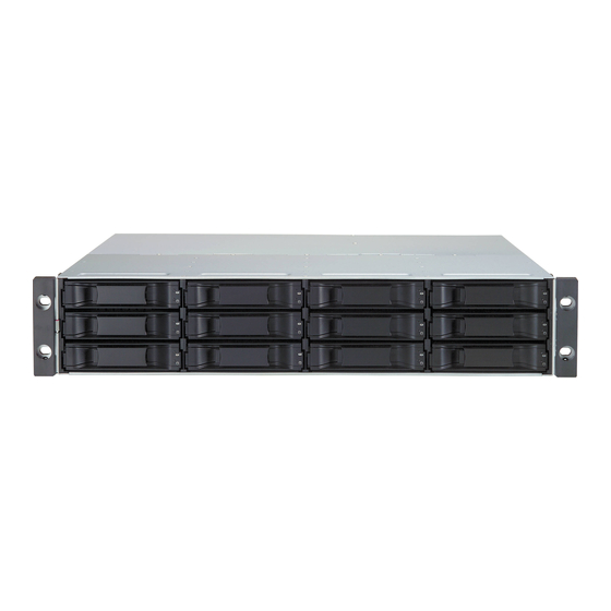
Chapter 2: VessRAID Installation This chapter covers the following topics: • Unpacking the VessRAID (below) • Installing the LCD Panel (Optional) (page 11) • Mounting VessRAID in a Rack (page 13) • Installing Disk Drives (page 15) • Making Data and Management Connections (page 18) •... - Page 26 VessRAID 1000i Series Product Manual VessRAID Models and Descriptions 1800i Drive Power 1700i Drive Power Model Slots Supplies Model Slots Supplies 1840i 1740i 1830i 1730i 1820i 1720i Figure 1. VessRAID 1730i or 1830i front view Drive Carrier LEDs Drive Carriers Power and Status LEDs A defective drive may be replaced without interruption of data availability to the host computer.
-
Page 27: Installing The Lcd Panel (Optional)
Chapter 2: VessRAID Installation Figure 3. VessRAID 1830i rear view RAID Controller Power Supply For a description of the LEDs, see pages 24 and 25. Installing the LCD Panel (Optional) Cautions • The LCD panel is NOT a hot-swap device. Be sure the VessRAID is powered down before you connect or disconnect the LCD panel. - Page 28 VessRAID 1000i Series Product Manual Insert the two screws that you removed in step 1 through the holes in the left bracket and into the threaded holes in the LCD panel, as shown in Figure 5. Tighten the screws to secure the LCD panel to the bracket. Figure 5.
-
Page 29: Mounting Vessraid In A Rack
Chapter 2: VessRAID Installation Mounting VessRAID in a Rack The VessRAID subsystem installs to the rack using the available mounting rails. You can also use your existing rails. Figure 6. VessRAID mounted in a rack with the available rails Vertical Rack Post VessRAID subsystem Mounting rails mount Handles mount... - Page 30 VessRAID 1000i Series Product Manual Place the VessRAID subsystem onto the rails. Secure the VessRAID subsystem to the rack through each handle, using the attaching screws from your rack system. Figure 7. Rack mount assembly diagram Rack front post Rack back post Locating pins (2 on each end) Rail attaching screws (not included)
-
Page 31: Installing Disk Drives
Chapter 2: VessRAID Installation Installing Disk Drives You can populate the VessRAID with SAS or SATA hard disk drives. For optimal performance, install physical drives of the same model and capacity. The drives’ matched performance allows the logical drive to function better as a single drive. The table below shows the number of drives required for each RAID level. - Page 32 VessRAID 1000i Series Product Manual Figure 9. VessRAID 1730i and 1830i drive slot numbering Figure 10.VessRAID 1720i and 1820i drive slot numbering Install all of the drive carriers into the VessRAID enclosure to ensure proper airflow, even if you do not populate all the carriers with disk drives.
-
Page 33: Installing Your Disk Drives
Chapter 2: VessRAID Installation Installing Your Disk Drives Remove a disk drive carrier. Carefully lay the disk drive into the drive carrier at the front, so that the screw holes on the sides line up. Insert the screws through the holes in the drive carrier and into the sides of the disk drive. -
Page 34: Making Data And Management Connections
VessRAID 1000i Series Product Manual Making Data and Management Connections You can configure your VessRAID for: • Direct Attached Storage (DAS), see below • Storage Area Network (SAN), see page 20 • JBOD Expansion to DAS or SAN (16- and 12-bay models), see page 22 Note VessRAID does not support cascading of multiple RAID subsystems. - Page 35 Chapter 2: VessRAID Installation Attach the other end of the Ethernet cable to the management port on the VessRAID subsystem. Figure 12.DAS data and management connections Std. NIC GbE NIC Host PC Management or Server Cables Std. Network Switch Data Cable VessRAID iSCSI Data Ports Management Port...
-
Page 36: Storage Area Network (San)
VessRAID 1000i Series Product Manual Storage Area Network (SAN) This arrangement requires: • A Gigabit Ethernet network interface card (GbE NIC) in the Host PC with iSCSI support (in hardware or software) • A GbE network switch • A standard network switch •... - Page 37 Chapter 2: VessRAID Installation If you have another iSCSI VessRAID subsystem, configure its Management Path in the same way. Figure 13.SAN data and management connections Std. NIC Std. NIC GbE NIC GbE NIC Host PCs or Servers Std. Network Switch Network Switch Management Cables...
-
Page 38: Jbod Expansion To Das Or San
VessRAID 1000i Series Product Manual JBOD Expansion to DAS or SAN The 16- and 12-bay VessRAID models have a JBOD expansion port. JBOD expansion is not possible with 8-bay VessRAID models. Configuring a Data Path To establish the data path: Connect the SAS Expansion port (with a diamond icon) of the VessRAID controller to the SAS IN port (with a circle icon) on the I/O module of the first VessJBOD. -
Page 39: Setting Up Serial Cable Connections
Chapter 2: VessRAID Installation Setting Up Serial Cable Connections Serial communication enables the Command Line Interface (CLI) and Command Line Utility (CLU) on your PC to monitor and control the VessRAID. The VessRAID package includes a RJ11-to-DB9 serial data cable. Figure 15. -
Page 40: Connecting The Power
VessRAID 1000i Series Product Manual Connecting the Power Plug-in the power cord on the power supply on the back of the VessRAID enclosure and switch on the power supply. If you have a redundant power supply, plug-in both power supplies and turn on both power supplies. Important If you have a JBOD Expansion, always power on the JBOD subsystems first. -
Page 41: Controller Leds
Chapter 2: VessRAID Installation Controller LEDs When boot-up is finished and the VessRAID subsystem is functioning normally: • Battery and Controller status LEDs display green continuously. • Ethernet LEDs display green or flash depending on your network connection. • iSCSI LEDs display green or flash depending on your data network activity. Figure 17.VessRAID Controller LEDs JBOD Expansion Port Fan 2... -
Page 42: Lcd Panel
VessRAID 1000i Series Product Manual LCD Panel The LCD panel activates approximately 35 seconds after you switch on the VessRAID’s power supply. At first, the LCD screen displays System is Initializing When the VessRAID is fully booted and running under normal conditions, the LCD screen shows the VessRAID model number and IP address, as shown in Figure 19. -
Page 43: Chapter 3: Vessraid Setup
Chapter 3: VessRAID Setup This chapter covers the following topics: • Setting up the Serial Connection (below) • Choosing DHCP or a Static IP Address (page 28) • Setting up with the CLI (page 29) • Setting up with the CLU (page 31) •... -
Page 44: Choosing Dhcp Or A Static Ip Address
VessRAID 1000i Series Product Manual Choosing DHCP or a Static IP Address When you setup your VessRAID, you have the option of: • Enabling DHCP and letting your DHCP server assign the IP address to the VessRAID’s management port. • Specifying a static IP address for the VessRAID’s management port. -
Page 45: Setting Up With The Cli
Chapter 3: VessRAID Setup Setting up with the CLI Type the following string to set the system date and time, then press Enter. administrator@cli> date -a mod -d 2009/01/25 -t 14:50:05 In the above example, the date and time are included as examples only. Your values will be different. - Page 46 VessRAID 1000i Series Product Manual To verify the settings, type net, and press Enter. administrator@cli> net =========================================== CId Port Type Mask Gateway Link =========================================== Mgmt 192.168.10.85 255.255.255.0 192.168.10.1 iSCSI 192.168.10.88 255.255.255.0 192.168.10.1 iSCSI 10.0.0.3 0.0.0.0 0.0.0.0 Down iSCSI 10.0.0.4 0.0.0.0 0.0.0.0 Down iSCSI...
-
Page 47: Setting Up With The Clu
Chapter 3: VessRAID Setup Setting up with the CLU At the administrator@cli> prompt, type menu and press Enter. The CLU main menu appears. Figure 2. CLU main menu With Quick Setup highlighted, press Enter. The first Quick Setup screen enables you to make Date and Time settings. Setting system date and time To make date and time settings: Press the arrow keys to highlight System Date. -
Page 48: Making Automatic Ip Settings
VessRAID 1000i Series Product Manual Press the backspace key to erase the current IP Address. Type the new IP Address. Follow the same procedure to specify the Subnet Mask, Gateway IP Address and DNS Server IP Address. If you do not have a DNS server, skip the DNS Server IP address. Highlight TCP Port Number to change the entry. -
Page 49: Setting Up With The Lcd
Chapter 3: VessRAID Setup Setting up with the LCD The LCD Panel displays the current IP address during normal operation. If you did not install the LCD Panel, see “Installing the LCD Panel (Optional)” on page 11. The LCD does not have a date and time function. Figure 3. -
Page 50: Making Automatic Ip Settings
VessRAID 1000i Series Product Manual Make the needed changes the same as in step 5. After you have set the last (extreme right) digit, press the button. The display says Save Network Setting? Press the button to confirm. The display shows the new IP address you set. Making Automatic IP Settings To make Management Port settings automatically: Press the... -
Page 51: Creating Disk Arrays With Webpam Proe
Chapter 3: VessRAID Setup Creating Disk Arrays with WebPAM PROe Note You can also use the CLU or the LCD panel to create disk arrays and logical drives. See page 158 or page 219 for more information. Setting up disk arrays with WebPAM PROe consists of the following actions: •... - Page 52 VessRAID 1000i Series Product Manual When the log-in screen (Figure 4) appears: • Type administrator in the User Name field. • Type password in the Password field. • Click the Login button. The User Name and Password are case sensitive. Figure 4.
-
Page 53: Selecting A Language
Chapter 3: VessRAID Setup Selecting a Language WebPAM PROe displays in English, German, French, Italian, Spanish, Russian, Japanese, Chinese Traditional, Chinese Simple, and Korean. Click Language on the WebPAM PROe banner. The language list appears in the Header. Click on the language you prefer. The WebPAM PROe user interface displays in the selected language. - Page 54 VessRAID 1000i Series Product Manual Figure 6. The Array Configuration menu Automatic When you choose the Automatic option, the following parameters appear on the screen: • Disk Arrays – The number of physical drives in the disk array, their ID numbers, configurable capacity, and the number of logical drives to be created •...
- Page 55 Chapter 3: VessRAID Setup Express When you choose the Express option, a set of characteristics and options appears on the screen. Check the boxes to select any one or a combination of: • Redundancy – The array will remain available if a physical drive fails •...
- Page 56 VessRAID 1000i Series Product Manual Advanced Note For an explanation of the parameters under the Advanced option, see. Step 1 – Disk Array Creation Enter a name for the disk array in the field provided. Check the boxes to enable the following features. •...
-
Page 57: Logging Out Of Webpam Proe
Chapter 3: VessRAID Setup Specify a Stripe size from the dropdown menu. 64, 128, 256, 512 KB, and 1 MB are available. 64 KB is the default. Specify a Sector size from the dropdown menu. 512 Bytes, 1, 2, and 4 KB are available. 512 Bytes is the default. Choose a Read Cache policy: Read Cache, Read Ahead Cache, and No Cache are available. -
Page 58: Using Webpam Proe Over The Internet
VessRAID 1000i Series Product Manual Using WebPAM PROe over the Internet The above instructions cover connections between VessRAID and your company network. It is also possible to connect to a VessRAID from the Internet. Your MIS Administrator can tell you how to access your network from outside the firewall. -
Page 59: Chapter 4: Management With Webpam Proe
Chapter 4: Management with WebPAM PROe This chapter covers the following topics: • Logging into WebPAM PROe (page 44) • Perusing the Interface (page 46) • Working with the Storage Network (page 51) • Working with Subsystems (page 52) • Managing Users (page 62) •... -
Page 60: Logging Into Webpam Proe
VessRAID 1000i Series Product Manual Logging into WebPAM PROe Launch your Browser. In the Browser address field, type the IP address of the VessRAID subsystem. See “Setting up the Serial Connection” on page 27. Note that the IP address shown below is only an example. The IP address you type into your browser will be different. -
Page 61: Selecting A Language
Chapter 4: Management with WebPAM PROe Figure 1. WebPAM PROe log-in screen After sign-in, the WebPAM PROe opening screen appears. If there are any unconfigured physical drives in the enclosure, an Array Configuration menu will also appear (see page 31). Note Make a Bookmark (Netscape Navigator) or set a Favorite (Internet Explorer) of the Login Screen so you can access it easily next... -
Page 62: Perusing The Interface
VessRAID 1000i Series Product Manual Figure 2. Clicking “Language” on the WebPAM PROe banner Perusing the Interface WebPAM PROe is browser-based RAID management software with a graphic user interface. Figure 3. WebPAM PROe interface... -
Page 63: Using The Header
Chapter 4: Management with WebPAM PROe There are four major parts to the graphic user interface: • Header (see below) • Tree (see page 47) • Management View (see page 48) • Event Frame (see page 49) Using the Header The Header contains the following items: •... -
Page 64: Using Management View
VessRAID 1000i Series Product Manual Figure 4. WebPAM PROe Tree View Name of logged-in user Subsystem IP address and model Physical Drives in this Enclosure Using Management View Management View provides the actual user interface with the VessRAID, including creation, maintenance, deletion, and monitoring of disk arrays and logical drives. -
Page 65: Viewing The Event Frame
Chapter 4: Management with WebPAM PROe Click the Help button in Management View to access online help for the function that is currently displayed. Viewing the Event Frame To view the Event Frame: Click View in the Header. Click the Show Event Frame popup option. The VessRAID user interface will display the Event Frame below Management View. - Page 66 VessRAID 1000i Series Product Manual Figure 5. Clicking “Logout” on the WebPAM PROe banner Clicking Logout brings you back to the Login Screen. See page 45. After logging out, you must enter your user name and password in order to log in again.
-
Page 67: Working With The Storage Network
Chapter 4: Management with WebPAM PROe Working with the Storage Network When you log into WebPAM PROe, you access a specific VessRAID subsystem. See “Logging into WebPAM PROe” on page 44. The Storage Network feature enables you to access all of the VessRAID subsytems with a Management Port connection to your network. -
Page 68: Working With Subsystems
VessRAID 1000i Series Product Manual Working with Subsystems A VessRAID subsystem is identified by its Management Port IP address. Subsystem functions include: • Viewing Subsystem Information (page 52) • Saving System Service Report (page 52) • Setting an Alias for the Subsystem (page 53) •... -
Page 69: Setting An Alias For The Subsystem
Chapter 4: Management with WebPAM PROe Setting an Alias for the Subsystem An alias is optional. To set an alias for this subsystem: In Tree View, click the Subsystem icon. In Management View, click the Settings tab. Enter a name into the Alias field. Maximum of 48 characters. -
Page 70: Saving The Runtime Event Log
VessRAID 1000i Series Product Manual • Time – Time and date of the occurrence • Description – A brief description of the event Click the link at the top of the column by which you want to sort the events. After you click the item, a triangle icon appears. -
Page 71: Saving Nvram Events
Chapter 4: Management with WebPAM PROe • Item Number – A consecutive decimal number assigned to a specific event • Device – Battery, controller, logical drive, physical drive, port, etc. • Event ID – The hexadecimal number that identifies the specific type of event •... -
Page 72: Viewing Current Background Activities
VessRAID 1000i Series Product Manual Viewing Current Background Activities To view the current background activities: In Tree View, click the Subsystem icon. In Management View, click the Background Activities tab. A list of current background activities appears, including: • Rebuild •... -
Page 73: Running Background Activities
Chapter 4: Management with WebPAM PROe • Reassigned Block Threshold – 1 to 512 blocks • Error Block Threshold – 1 to 1024 blocks Check to enable or uncheck to disable the following functions: • Media Patrol – Checks the magnetic media on physical drives •... -
Page 74: Running Pdm
VessRAID 1000i Series Product Manual Running PDM Predictive Data Migration (PDM) migrates data from the suspect physical drive to a spare disk drive, similar to Rebuilding. But unlike Rebuilding, PDM acts before the disk drive fails and your Logical Drive goes Critical. You an also run PDM on a specific disk array, see “Running PDM on a Disk Array”... -
Page 75: Deleting A Scheduled Activity
Chapter 4: Management with WebPAM PROe • Monthly – Choose a calendar day of the month (1 – 31). If you choose a higher number than there are days in the current month, the actual start date will occur at the beginning of the following month. Or, choose a day of the week and choose the first, second, third, fourth, or last occurrence of that day in the month. -
Page 76: Viewing Lock Status
VessRAID 1000i Series Product Manual Viewing Lock Status The lock prevents other sessions (including by the same user) from making a configuration change to the controller until the lock expires or a forced unlock is done. To view the lock status for this subsystem: Click the Subsystem icon Tree View. -
Page 77: Releasing The Lock
Chapter 4: Management with WebPAM PROe Enter a time interval between 1 and 1440 minutes (one day) that you want the lock to stay active. The renew time replaces the previous Expiration Time. Click the Submit button. Releasing the Lock The lock prevents other sessions (including by the same user) from making a configuration change to the controller until the lock expires or a forced unlock is done. -
Page 78: Managing Users
VessRAID 1000i Series Product Manual Managing Users User Management includes all functions dealing with user accounts. Functions include: • Viewing User Information (page 62) • Making User Settings (page 62) • Making Your Own User Settings (page 63) • Setting-up User Event Subscriptions (page 63) •... -
Page 79: Making Your Own User Settings
Chapter 4: Management with WebPAM PROe • Enter or change the email address. • From the Privilege dropdown menu, choose a new level. See “List of User Privileges” on page 65 Click the Submit button. The Administrator or Super User can change another user’s password. See “Changing Another User’s Password”... -
Page 80: Changing Another User's Password
VessRAID 1000i Series Product Manual • Fatal – Non-Recoverable error or failure has occurred • None – Deactivates this event for notification purposes Click the Submit button. The user’s account must have an email address. See “Making User Settings” on page 62. -
Page 81: Creating A User
Chapter 4: Management with WebPAM PROe Enter the new password in the Retype Password field. Click the Submit button. Creating a User To create a user: Log into WebPAM PROe as the Administrator or a Super User. Click the Subsystem icon in Tree View. -
Page 82: Deleting A User
VessRAID 1000i Series Product Manual Deleting a User There will always be at least one Super User account. You cannot delete the user account you used to log in. To delete a user: Log into WebPAM PROe as the Administrator or a Super User. Click the Subsystem icon in Tree View. -
Page 83: Chapter 4: Management With Webpam Proe, Cont
Chapter 4: Management with WebPAM PROe Managing the Network Connection The network connection deals with the VessRAID’s Management Port. • Making Management Port Settings (below) • Making iSCSI Port Settings (page 67) Making Management Port Settings When you log into WebPAM PROe over your network, you use the VessRAID’s management port. - Page 84 VessRAID 1000i Series Product Manual Click the iSCSI Ports tab. Click one of the Port Configuration links. To enable DHCP, check the DHCP box. When DHCP is NOT enabled, enter: • Primary IP address • Primary subnet mask • Default gateway IP address Enter a TCP port number.
-
Page 85: Managing Iscsi Connections
Chapter 4: Management with WebPAM PROe Managing iSCSI Connections iSCSI connections deal with the VessRAID’s four host data ports. • Viewing iSCSI Node Information (below) • Making iSCSI Node Settings (below) • Viewing iSCSI Target Ports (page 70) • Viewing the iSCSI Portal (page 71) •... -
Page 86: Viewing Iscsi Target Ports
VessRAID 1000i Series Product Manual Enter a value in the field for each of the following items: • Node Name – An iSCSI node is identified by its name. • Node Alias – Optional. Maximum of 31 characters. Use letters, numbers, space between words and underscore. -
Page 87: Viewing The Iscsi Portal
Chapter 4: Management with WebPAM PROe The Target Ports tab displays the following information: • Controller ID – 1 • Port ID – 1, 2, 3, or 4 • Max Receive Data Segment Length – 8 KB is the default •... -
Page 88: Working With Iscsi Isns
VessRAID 1000i Series Product Manual iSCSI session information includes: • Index – VessRAID iSCSI session index number. • Device Name – iSCSI initiator on the Host PC. • Port ID – ID number of the port on the iSCSI HBA card in the Host PC. •... -
Page 89: Working With Iscsi Chaps
Chapter 4: Management with WebPAM PROe Make the following changes as needed: • Check the box to enable iSNS. • Enter the iSNS server IP address. • Enter a iSNS TCP Port number (3205 for most applications). Click the Submit button. Note Edge Side Includes (ESI) is a markup language that enables dynamic assembly of web page elements in servers across a... - Page 90 VessRAID 1000i Series Product Manual Click the iSCSI Management icon. Click the CHAP tab in Management View. The CHAP tab displays the list of current CHAPs. Adding CHAPs To add a CHAP: Click the Subsystem icon in Tree View. Click the Administrative Tools icon.
-
Page 91: Using Iscsi Ping
Chapter 4: Management with WebPAM PROe Deleting CHAPs To delete a CHAP: Click the Subsystem icon in Tree View. Click the Administrative Tools icon. Click the iSCSI Management icon. Click the CHAP tab dropdown menu and choose Delete CHAP. Check the box to the left of the CHAP you want to delete. Click the Submit button. -
Page 92: Managing Storage Services
VessRAID 1000i Series Product Manual Managing Storage Services Storage services deal with initiators and LUN mapping. LUN masking is the process of applying a LUN Map so that each initiator can only access the LUNs specified for it. • Adding an Initiator (page 76) •... -
Page 93: Viewing The Lun Map
Chapter 4: Management with WebPAM PROe Check the box to the left of the initiator you want to delete. Click the Submit button. Viewing the LUN Map To view the current LUN Map: Click the Subsystem icon in Tree View. Click the Administrative Tools icon. -
Page 94: Editing A Lun Map
VessRAID 1000i Series Product Manual Editing a LUN Map To edit the LUN Map: Click the Subsystem icon in Tree View. Click the Administrative Tools icon. Click the Storage Services icon. Click the LUN Map tab in Management View. From the LUN Mapping & Masking Information list, choose an initiator and click its link. -
Page 95: Managing Software Services
Chapter 4: Management with WebPAM PROe Managing Software Services Software Services include the following functions: • Making Email Settings (page 79) • Making SLP Settings (page 80) • Making Web Server Settings (page 81) • Making Telnet Settings (page 82) •... -
Page 96: Making Slp Settings
VessRAID 1000i Series Product Manual Changing the Startup Setting Under Startup Type: • Click the Automatic option to start the service automatically during system startup. Recommended. • Click the Manual option to start the service manually (the service does not start during system startup). Click the Submit button. -
Page 97: Making Web Server Settings
Chapter 4: Management with WebPAM PROe Starting or Restarting SLP service To start or restart the SLP service, click the Start or Restart button. Making Web Server Settings The Web Server service connects your browser to the WebPAM PROe GUI on the VessRAID subsystem. -
Page 98: Making Telnet Settings
VessRAID 1000i Series Product Manual Click OK in the confirmation box. Starting or Restarting Web Server service To start or restart the Web Server service, click the Start or Restart button. Making Telnet Settings VessRAID’s Telnet service enables you to access VessRAID’s Command Line Interface (CLI) through a network connection. -
Page 99: Making Snmp Settings
Chapter 4: Management with WebPAM PROe Starting or Restarting Telnet service To start or restart the Telnet service, click the Start or Restart button. Making SNMP Settings VessRAID’s SNMP service enables the SNMP browser to obtain information from the VessRAID. The Trap Sink is where SNMP events are sent and can be viewed. -
Page 100: Making Netsend Settings
VessRAID 1000i Series Product Manual Click the Submit button. Click OK in the confirmation box. Deleting Trap Sinks To delete a trap sink: Highlight the trap sink you want to delete from the list. Click the Delete button to remove the trap sink from the list. Click the Submit button. - Page 101 Chapter 4: Management with WebPAM PROe Adding Netsend recipients See “Netsend Requirements” on page 85. To add a Netsent recipient: In the Recipient Address field, type the IP address of the recipient PC. Under Recipient filter, choose the lowest level of Severity to be reported for each event.
- Page 102 VessRAID 1000i Series Product Manual If your Netsend and Messenger service settings are correct but the recipient PC does not receive event messages, check the recipient PC’s Firewall settings. Refer to your OS documentation for more information.
-
Page 103: Exporting The User Database
Chapter 4: Management with WebPAM PROe Exporting the User Database You can export the User Database file to share user information and settings among multiple VessRAID subsystems. The Export action saves a text file a designated folder the Host PC. From there, you can import the User Database file to other VessRAID subsystems. -
Page 104: Importing A Configuration Script
VessRAID 1000i Series Product Manual Under the Type dropdown list, choose User Database. Enter the name of the file to be imported. Or, click the Browse... button to search for the file. Look for a file called export. Click the Submit button. Click the Next button. -
Page 105: Updating The Firmware
Chapter 4: Management with WebPAM PROe The new configuration is applied to this VessRAID subsystem. Note The Decryption box is grayed out. Decryption is disabled for configuration scripts. Updating the Firmware See “Chapter 7: Maintenance” on page 231 for instructions. Viewing Flash Image Information Flash image information refers to the package of firmware components running on your VessRAID controller or controllers, including:... -
Page 106: Restoring Factory Defaults
VessRAID 1000i Series Product Manual Restoring Factory Defaults VessRAID includes a function to restore the default settings to its Firmware and Software settings. Caution The action of restoring default settings can disrupt your VessRAID functions. Use this feature only when necessary and only the settings that must reset to default in order to set them correctly. -
Page 107: Shutting Down The Subsystem
Chapter 4: Management with WebPAM PROe Shutting Down the Subsystem You can only do part of this function in WebPAM PROe. Additional action is required, as described below. Important If you have a JBOD Expansion, always power off the RAID subsystem first. -
Page 108: Monitoring The Shutdown
VessRAID 1000i Series Product Manual Monitoring the Shutdown To monitor a shutdown, you must use the Command Line Interface (CLI) though a serial connection to the VessRAID. Turn off both power supply switches when the following this message appears: Shutdown complete. It is now safe to power off the subsystem. -
Page 109: Starting Up After Shutdown
Chapter 4: Management with WebPAM PROe Starting Up After Shutdown Important If you have a JBOD Expansion, always power on the JBOD subsystems first. Then power on the RAID subsystem. To start the RAID subsystem: Manually turn on the power supply switches on the back of the subsystem. If the switches are ON but the subsystem is OFF, turn the switches off and on again. -
Page 110: Restarting The Subsystem
VessRAID 1000i Series Product Manual Restarting the Subsystem Note If you have a JBOD Expansion, you are not required to restart the JBOD subsystems when you restart the RAID subsystem. You can only do part of this function in WebPAM PROe. Additional action is required, as described below. -
Page 111: Managing The Controller
Chapter 4: Management with WebPAM PROe Managing the Controller The RAID controller is the heart of the VessRAID subsystem. Controller management includes the following functions: • Viewing Controller Information (page 95) • Viewing Controller Information (page 95) • Viewing Controller Statistics (page 96) •... -
Page 112: Viewing Controller Statistics
VessRAID 1000i Series Product Manual • Write Back Cache Flush Interval • Enclosure Polling Interval See “Making Controller Settings” on page 96. Upgradable items You can upgrade the following items: • Boot loader Version • Firmware Version number • Software Version number •... -
Page 113: Clearing An Orphan Watermark
Chapter 4: Management with WebPAM PROe • Enter a polling interval (1 to 1440 minutes) in SMART Polling Interval field. • Check the Coercion Enabled box to enable disk drive capacity coercion. When disk drives of different capacities are used in the same array, coercion reduces the usable capacity of the larger disk drive(s) in order to match the smallest capacity drive. - Page 114 VessRAID 1000i Series Product Manual The changes take effect immediately.
-
Page 115: Managing Enclosures
Chapter 4: Management with WebPAM PROe Managing Enclosures On VessRAID, enclosures include the main VessRAID subsystem or Head Unit as well as VessJBOD enclosures that are connected through expansion. Enclosure Management includes the following functions: • Viewing the Enclosure (page 99) •... -
Page 116: Viewing Enclosure Topology
VessRAID 1000i Series Product Manual Figure 6. Disk Status LED Disk Status Figure 7. VessRAID enclosure LEDs USB 1 Dirty Cache USB 2 Controller Status Fan 2 Fan 1 Battery Viewing Enclosure Topology To view Enclosure Topology: Click the Subsystem icon in Tree View. -
Page 117: Making Enclosure Settings
Chapter 4: Management with WebPAM PROe Click the Enclosures icon. Click the Enclosure icon. Enclosure information appears the Information tab in Management View. You can monitor power supplies, fans, enclosure temperatures and voltages, and the battery. Adjustable items You can set or adjust the following items: •... -
Page 118: Checking The Battery
VessRAID 1000i Series Product Manual Click the Enclosure icon. Click the FRU VPD tab in Management View. Use this information when communicating with Technical Support and when ordering replacement units. For contact information, see “Contacting Technical Support” on page 319. Checking the Battery A cache backup battery or Battery Backup Unit (BBU) is optional on VessRAID. -
Page 119: Reconditioning A Battery
Chapter 4: Management with WebPAM PROe Reconditioning a Battery A cache backup battery or Battery Backup Unit (BBU) is optional on VessRAID. To recondition the battery: Click the Subsystem icon in Tree View. Click the Enclosures icon. Click the Enclosure icon. -
Page 120: Testing The Buzzer
VessRAID 1000i Series Product Manual In Management View, from the Buzzer tab dropdown menu, choose Settings. Check the Buzzer Enable box to enable the buzzer. Uncheck the Buzzer Enable box if you do not want the buzzer to sound. Click the Submit button. Testing the Buzzer You must enable the buzzer before you can test it. -
Page 121: Managing Physical Drives
Chapter 4: Management with WebPAM PROe Managing Physical Drives Managing Physical Drives deals with the physical disk drives installed in the VessRAID subsystem enclosure, including the following functions: • Viewing a List of Physical Drives (page 105) • Identifying a Physical Drive (page 105) •... -
Page 122: Making Global Physical Drive Settings
VessRAID 1000i Series Product Manual Making Global Physical Drive Settings Global settings apply to all of the physical disk drives installed in the VessRAID subsystem enclosure. To make global physical drive settings: Click the Subsystem icon in Tree View. Click the Enclosures icon. -
Page 123: Viewing Physical Drive Statistics
Chapter 4: Management with WebPAM PROe • Operational Status – OK is normal. Can also show Rebuilding, Forced Online, Forced Offline, Transition Running, PDM Running, Media Patrol Running, Stale, PFA, Offline, or Dead. • Configuration Status – The array to which the drive is assigned or its spare designation, including Unconfigured, Stale, PFA, Global Spare, Dedicated Spare, Revertible Global Spare, Revertible Dedicated Spare. -
Page 124: Clearing Stale And Pfa Conditions
VessRAID 1000i Series Product Manual Click the Settings tab in Management View. Type an alias into the Physical Drive Alias field. Maximum of 31 characters. Use letters, numbers, space between words, and underscore. An alias is optional. Click the Submit button. Clearing Stale and PFA Conditions The Clear tab only appears when those conditions are present. -
Page 125: Locating A Physical Drive
Chapter 4: Management with WebPAM PROe Caution Forcing a physical drive offline or online is likely to cause data loss. Back up your data before you proceed. Use these functions only when required. Important Forcing a physical drive offline will cause your logical drives to become degraded. - Page 126 VessRAID 1000i Series Product Manual Figure 8. Disk Status LED Disk Status...
-
Page 127: Managing Ups Units
Chapter 4: Management with WebPAM PROe Managing UPS Units Uninterruptible Power Supply (UPS) Management includes the following functions: • Viewing a List of UPS Units (below) • Making UPS Settings (page 112) • Viewing UPS Information (page 113) Viewing a List of UPS Units To view a list of UPS units supporting the VessRAID: Click the Subsystem icon in Tree View. -
Page 128: Making Ups Settings
VessRAID 1000i Series Product Manual Making UPS Settings These settings control how the VessRAID subsystem detects the UPS unit and responds to data reported by the UPS unit. To make UPS settings: Click the Subsystem icon in Tree View. Click the UPS icon. -
Page 129: Viewing Ups Information
Chapter 4: Management with WebPAM PROe Notes 1. Detection Setting must be set to Auto. If a UPS is detected, the setting changes to Enable. 2. The maximum recommended Loading Ratio varies among models of UPS units. The general range is 60% to 80%. Viewing UPS Information To view information about a specific UPS unit: Click the Subsystem... -
Page 130: Managing Disk Arrays
VessRAID 1000i Series Product Manual Managing Disk Arrays Disk Array Management includes the following functions: • Viewing Disk Arrays (page 114) • Creating a Disk Array (page 114) • Deleting a Disk Array (page 119) • Viewing Disk Array Information (page 119) •... -
Page 131: Creating A Disk Array - Automatic
Chapter 4: Management with WebPAM PROe • Advanced – You directly specify all parameters for a new disk array. Makes one logical drive automatically. You can create additional logical drives at a later time, if additional configurable capacity is available. Does not make a hot spare drive. -
Page 132: Creating A Disk Array - Express
VessRAID 1000i Series Product Manual Creating a Disk Array – Express The Disk Array Express Creation option enables you to choose the parameters for a new disk array by specifying the characteristics you want. With this method, you can create multiple logical drives at the same time you create your disk array. However, all of the logical drives will be the same. -
Page 133: Creating A Disk Array - Advanced
Chapter 4: Management with WebPAM PROe The following parameters display: • Disk Arrays – The number of physical drives in the disk array, their slot numbers, configurable capacity, and the number of logical drives to be created • Logical Drives – The slot number of the logical drive(s), their RAID level, capacity, and stripe size •... - Page 134 VessRAID 1000i Series Product Manual migration of data from the suspect drive (the disk drive with the bad sectors) to a spare disk drive. From the Media Type dropdown menu, choose the physical drive type to use in the array. •...
-
Page 135: Deleting A Disk Array
Chapter 4: Management with WebPAM PROe 11. When you have finished specifying logical drives, click the Next button. Step 3 – Summary The Summary lists the disk array and logical drive information you specified. To proceed with disk array and logical drive creation, click the Submit button. Note This function does not automatically create a hot spare drive. -
Page 136: Making Disk Array Settings
VessRAID 1000i Series Product Manual Disk Array Operational Status • OK – The normal state of a disk array. For RAID Levels other than RAID 0 (Striping), the disk array has full redundancy. • Synchronizing – When you first create a disk array, the disk array synchronizes. -
Page 137: Creating A Logical Drive
Chapter 4: Management with WebPAM PROe Creating a Logical Drive When you create a disk array, you automatically create one logical drive also. If the initial logical drive used less than the full capacity of the disk array, you can create additional logical drives from the same disk array. -
Page 138: Deleting A Logical Drive
VessRAID 1000i Series Product Manual 13. Click the Update button to enter the logical drive parameters. 14. Review the results. If there is remaining space the disk array, you can create another logical drive, following the steps above. Each logical drive can have a different set of parameters. -
Page 139: Rebuilding A Disk Array
Chapter 4: Management with WebPAM PROe For a list of Migration options and other important information, see “RAID Level Migration” on page 264. Notes • You can add physical drives to a RAID 50 or RAID 60 array but you cannot change the number of axles. •... -
Page 140: Running Media Patrol On A Disk Array
VessRAID 1000i Series Product Manual Rebuilding Automatically Normally, a disk array would rebuild itself using a hot disk drive, after going Critical. However, if the Auto Rebuild function is disabled or no spare drives are available, you must initiate the procedure. To enable Auto Rebuild, see “Making Background Activity Settings”... -
Page 141: Running Pdm On A Disk Array
Chapter 4: Management with WebPAM PROe To start Media Patrol: Click the Subsystem icon in Tree View. Click the Disk Arrays icon. Click the Disk Array icon. From the dropdown menu the Background Activities tab, choose Start Media Patrol. Click the Start button. Running PDM on a Disk Array Predictive Data Migration (PDM) migrates data from the suspect physical drive to a spare physical drive, similar to Rebuilding. -
Page 142: Preparing A Disk Array For Transport
VessRAID 1000i Series Product Manual To run Transition: Click the Subsystem icon in Tree View. From the dropdown menu on the Background Activities tab, choose Start Transition. Choose an unconfigured physical drive from the list of available drives. From the Target Physical Drive dropdown menu, choose an unconfigured physical drive. -
Page 143: Managing Logical Drives
Chapter 4: Management with WebPAM PROe Managing Logical Drives Logical drives are made from disk arrays. In the Tree, you can see a graphic representation of the logical drives that belong to each array. You can see a summary of all logical drives in the subsystem under Logical Drive Summary. Logical drive management includes the following functions: •... -
Page 144: Viewing Logical Drive Information
VessRAID 1000i Series Product Manual may remain intact. You must determine the cause of the problem and correct it. “Critical & Offline Disk Arrays” on page 302 • Transport Ready – The result of a successful Prepare for Transport operation. You remove the physical drives of this logical drive and move them to another enclosure or to different drive slots in the same enclosure. -
Page 145: Viewing Logical Drive Statistics
Chapter 4: Management with WebPAM PROe Viewing Logical Drive Statistics To view information for a single logical drive: Click the Subsystem icon in Tree View. Click the Disk Arrays icon. Click the Disk Array icon. Click the Logical Drives icon Click the Logical Drive icon. -
Page 146: Running Redundancy Check
VessRAID 1000i Series Product Manual because there may be residual data the logical drives left behind from earlier configurations. For this reason, Initialization is recommended for all new logical drives. Caution When you initialize a logical drive, all the data the logical drive will be lost. -
Page 147: Viewing The Logical Drive Check Table
Chapter 4: Management with WebPAM PROe Click the icon of the logical drive you want to Initialize. You can also start Redundancy check from the Subsystem icon Background Activities tab From the dropdown menu on the Background Activities tab, choose Redundancy Check. -
Page 148: Making Logical Drive Lun Settings
VessRAID 1000i Series Product Manual Table Definitions • Read Check Table – Contains a list of read errors for this logical drive. • Write Check Table – Contains a list of write errors for this logical drive. • Inconsistent Block Table – Contains a list of inconsistent blocks for this logical drive. -
Page 149: Managing Spare Drives
Chapter 4: Management with WebPAM PROe Managing Spare Drives When a physical drive in a disk array fails and a spare drive of adequate capacity is available, the disk array will begin to rebuild automatically using the spare drive. See “Critical & Offline Disk Arrays” on page 302. Spare drive management includes the following functions: •... -
Page 150: Creating A Spare Drive
VessRAID 1000i Series Product Manual Click the Spare Drive icon. In Management View, the Enclosure Front View diagram appears with the location of the spare drive highlighted. Creating a Spare Drive Important • There must be an unconfigured physical drive available for selection as a spare drive. -
Page 151: Deleting Spare Drive
Chapter 4: Management with WebPAM PROe 10. If you selected a Dedicated spare drive, in the Dedicated to Disk Arrays field, highlight disk arrays to which you want assign the spare drive from the Available list and press the >> button to move the array to the Selected list. You can also double-click arrays to move them. -
Page 152: Running Spare Check
VessRAID 1000i Series Product Manual If you selected a Dedicated spare drive, in the Dedicated to Disk Arrays field, highlight the disk arrays to which you want assign the spare drive from the Available list and press the >> button to move them to the Selected list. You can also double-click array to move it. -
Page 153: Working With The Logical Drive Summary
Chapter 4: Management with WebPAM PROe Working with the Logical Drive Summary The Logical Drive Summary displays a list of all logical drives in the VessRAID enclosure plus the expanded or cascaded enclosures. This list does not arrange the logical drives under the disk array to which they belong nor under the enclosure in which they are located. - Page 154 VessRAID 1000i Series Product Manual...
-
Page 155: Chapter 5: Management With The Clu
Chapter 5: Management with the CLU This chapter covers the following topics: • Initial Connection (page 140) • Running Quick Setup (page 144) • Managing the Subsystem (page 145) • Managing the Controller (page 147) • Managing the Enclosure (page 150) •... -
Page 156: Initial Connection
VessRAID 1000i Series Product Manual Initial Connection Making an initial connection includes the following functions: • Making a Serial Connection (below) • Making a Telnet Connection (page 141) • Logging In (page 141) • Accessing Online Help (page 143) • Exiting the CLU (page 143) •... -
Page 157: Making A Telnet Connection
Chapter 5: Management with the CLU Making a Telnet Connection A Telnet connection requires a network connection between the Host PC and VessRAID controller’s Management (Ethernet) port. Figure 2. Management port on the controller Management port To start the telnet program: Go to the command line prompt (Windows) or click the terminal icon (Linux). - Page 158 VessRAID 1000i Series Product Manual Figure 3. CLU main menu Quick Setup – A sequence of four steps to setup System Date & Time, Management Port, and RAID Configuration. Subsystem Management – View controller information, lock/unlock the controller, set date and time, and monitor the enclosure. Physical Drive Management –...
-
Page 159: Accessing Online Help
Chapter 5: Management with the CLU Background Activity – Settings for Media Patrol, Auto Rebuild, Rebuild, Migration, PDM, Transition, Synchronization, Initialization, Redundancy Check rate, and thresholds. Event Viewer – View the event logs. Additional Info and Management – Spare Drives, LUN Mapping, User management, Email, SLP, Web Server, Telnet, SNMP, and Netsend settings, firmware flash, clear statistics and restore factory default settings. -
Page 160: Running Quick Setup
VessRAID 1000i Series Product Manual Running Quick Setup Quick Setup is discussed under “Setting up with the CLU” on page 31. -
Page 161: Managing The Subsystem
Chapter 5: Management with the CLU Managing the Subsystem Subsystem Management includes the following functions: • Setting an Alias for the Subsystem (page 145) • Running Media Patrol (page 145) • Locking or Unlocking the Subsystem (page 145) • Setting Subsystem Date and Time (page 146) Setting an Alias for the Subsystem An alias is optional. -
Page 162: Setting Subsystem Date And Time
VessRAID 1000i Series Product Manual Highlight Lock and press Enter. Resetting the Lock To reset the lock with a new time: From the Main Menu, highlight Subsystem Management and press Enter. Highlight Lock Management and press Enter. In the Lock Time field, type a lock time in minutes. 1 to 1440 minutes (24 hours) Highlight Renew and press Enter. -
Page 163: Managing The Controller
Chapter 5: Management with the CLU Managing the Controller Controller Management includes the following functions: • Viewing Controller Information (page 147) • Clearing an Orphan Watermark (page 147) • Making Controller Settings (page 147) • Locating the Controller (page 148) Viewing Controller Information Controller Management includes information, settings and statistics. -
Page 164: Locating The Controller
VessRAID 1000i Series Product Manual Highlight the controller you want and press Enter. Highlight Controller Settings and press Enter. Make the following settings as required: • Type and alias into the Alias field. Maximum of 48 characters. Use letters, numbers, space between words and underscore. - Page 165 Chapter 5: Management with the CLU Figure 4. Controller Status LED Controller Status...
-
Page 166: Managing The Enclosure
VessRAID 1000i Series Product Manual Managing the Enclosure Enclosure Management includes the following functions: • Viewing Enclosure Information (page 150) • Viewing Power Supply Status (page 150) • Locating a Power Supply (page 151) • Viewing Cooling Unit Status (page 151) •... -
Page 167: Locating A Power Supply
Chapter 5: Management with the CLU Locating a Power Supply To locate a power supply: From the Main Menu, highlight Subsystem Management and press Enter. Highlight Enclosure Management and press Enter. Highlight Power Supplies and press Enter. Highlight Locate Power Supply and press Enter. The LED on the selected power supply blinks for one minute. -
Page 168: Setting Temperature Thresholds
VessRAID 1000i Series Product Manual Setting Temperature Thresholds To change temperature thresholds: From the Main Menu, highlight Subsystem Management and press Enter. Highlight Enclosure Management and press Enter. Highlight Enclosure Settings and press Enter. Highlight the Temperature Warning threshold you want to change. Press the backspace key to erase the current value. -
Page 169: Reconditioning A Battery
Chapter 5: Management with the CLU controller before reconditioning is finished, the battery is charged to 100%, then reconditioning starts again. Reconditioning a Battery To recondition the subsystem battery: From the Main Menu, highlight Subsystem Management and press Enter. Highlight Enclosure Management and press Enter. Highlight Batteries and press Enter. -
Page 170: Viewing Enclosure Topology
VessRAID 1000i Series Product Manual Figure 6. VessRAID enclosure LEDs USB 1 Dirty Cache USB 2 Controller Status Fan 2 Fan 1 Battery Viewing Enclosure Topology Enclosure topology refers to the manner in which the data paths among the enclosures are connected: •... -
Page 171: Managing Physical Drives
Chapter 5: Management with the CLU Managing Physical Drives Physical Drive Management includes the following functions: • Making Global Physical Drive Settings (page 155) • Setting an Alias (page 156) • Viewing Advanced Information (page 156) • Viewing Physical Drive Statistics (page 156) •... -
Page 172: Setting An Alias
VessRAID 1000i Series Product Manual Setting an Alias An alias is optional. To set an Alias for a physical drive: From the Main Menu, highlight Physical Drive Management and press Enter. Highlight the physical drive of your choice and press Enter. Type an alias into the Alias field. -
Page 173: Forcing A Physical Drive Offline Or Online
Chapter 5: Management with the CLU After you clear a PFA error, watch for another PFA error to appear. If it does, replace the physical drive. Forcing a Physical Drive Offline or Online This function enables you to force an: •... -
Page 174: Managing Disk Arrays
VessRAID 1000i Series Product Manual Managing Disk Arrays Disk Array Management includes the following functions: • Creating a Disk Array (page 158) • Deleting a Disk Array (page 162) • Viewing Disk Array Information (page 162) • Setting an Alias for a Disk Array (page 163) •... -
Page 175: Creating A Disk Array - Automatic
Chapter 5: Management with the CLU Creating a Disk Array – Automatic To create a disk array using the Automatic feature: From the Main Menu, highlight Disk Array Management and press Enter. Highlight Create New Array and press Enter. Highlight Configuration Method and press the spacebar to toggle to Automatic. -
Page 176: Creating A Disk Array - Express
VessRAID 1000i Series Product Manual Creating a Disk Array – Express To create a disk array using the Express feature: From the Main Menu, highlight Disk Array Management and press Enter. Highlight Create New Array and press Enter. Highlight Configuration Method and press the spacebar to toggle to Express. Highlight Configuration Method and press to spacebar to choose each of the following characteristics for your disk array: •... -
Page 177: Creating A Disk Array - Advanced
Chapter 5: Management with the CLU Creating a Disk Array – Advanced For more information on the choices below, see “Chapter 8: Technology Background” on page 245. To create a disk array: From the Main Menu, highlight Disk Array Management and press Enter. Highlight Create New Array and press Enter. -
Page 178: Deleting A Disk Array
VessRAID 1000i Series Product Manual 17. Highlight Save Logical Drive and press Enter. 18. Review logical drive(s) you are about to create for your new array. Then do one of the following actions: • If you agree with the logical drive(s) as specified, highlight Complete Disk Array Creation and press Enter. -
Page 179: Setting An Alias For A Disk Array
Chapter 5: Management with the CLU • Synchronizing – When you first create a disk array, the disk array synchronizes. During that time, your data is available. However, access will be slower until synchronizing is done. • Critical/Degraded – This condition results from a physical drive failure. Your data is still available. -
Page 180: Enabling Media Patrol On A Disk Array
VessRAID 1000i Series Product Manual Enabling Media Patrol on a Disk Array Media Patrol checks the magnetic media on physical drives. To enable or disable Media Patrol: From the Main Menu, highlight Disk Array Management and press Enter. Highlight the disk array you want and press Enter. Highlight Media Patrol and press the spacebar to toggle between Enable and Disable. -
Page 181: Migrating A Disk Array
Chapter 5: Management with the CLU The available drives are either HDD or SSD, depending on the type of drives in the array. Highlight Start and press Enter. Migrating a Disk Array In order to migrate RAID level, you may have to add physical drives. For more information, see “RAID Level Migration”... -
Page 182: Running Pdm
VessRAID 1000i Series Product Manual The screen jumps to Disk Arrays Summary. Running PDM Be sure PDM must be enabled. See “Enabling PDM on a Disk Array” on page 164. To run Predictive Data Migration on a disk array: From the Main Menu, highlight Disk Array Management and press Enter. Highlight the disk array you want and press Enter. -
Page 183: Creating A Logical Drive
Chapter 5: Management with the CLU To locate a disk array: From the Main Menu, highlight Disk Array Management and press Enter. Highlight the disk array you want and press Enter. Highlight Locate Disk Array and press Enter. The disk status LEDs for the physical drives in the disk array blink for one minute. -
Page 184: Deleting A Logical Drive
VessRAID 1000i Series Product Manual Highlight the following parameters and press the spacebar to toggle though the available choices: • Stripe size – Press the spacebar to choose: 64 KB, 128 KB, 256 KB, 512 KB, or 1 MB • Sector size –... -
Page 185: Managing Spare Drives
Chapter 5: Management with the CLU Managing Spare Drives Spare Drive Management includes the following functions: • Viewing a list of Spare Drives (page 169) • Creating a Spare Drive (page 169) • Making Spare Drive Settings (page 170) • Running Spare Check (page 170) •... -
Page 186: Making Spare Drive Settings
VessRAID 1000i Series Product Manual Highlight Spare Type and press the spacebar to toggle between Dedicated and Global. Dedicated means this spare drive can only be used with the specified disk arrays. Global means this spare drive can be used by any disk array. If you chose Dedicated, highlight Dedicated to Arrays and press the backspace key to erase the current value, then type the new value. -
Page 187: Deleting A Spare Drive
Chapter 5: Management with the CLU Deleting a Spare Drive Caution If the spare drive you delete is the only spare, the controller will not rebuild a critical array until you provide a new spare drive. To delete a spare drive: From the Main Menu, highlight Spare Drive Management and press Enter. -
Page 188: Managing Logical Drives
VessRAID 1000i Series Product Manual Managing Logical Drives The Logical Drive Management function deals with settings and functions of existing logical drives. To create or delete a logical drive, see “Managing Disk Arrays” on page 158. Logical drive management includes: •... -
Page 189: Setting Read Cache Policy
Chapter 5: Management with the CLU To set write cache policy for this logical drive, highlight WritePolicy and press the spacebar to toggle between WriteBack and WriteThru (write though). Press Ctrl-A to save your settings. Setting Read Cache Policy To set read cache policy on a logical drive: From the Main Menu, highlight Logical Drive Management and press Enter. -
Page 190: Running Redundancy Check
VessRAID 1000i Series Product Manual Running Redundancy Check Redundancy Check is a maintenance procedure for logical drives in fault-tolerant disk arrays that ensures all the data matches exactly. To run Redundancy Check: From the Main Menu, highlight Logical Drive Management and press Enter. Highlight the logical drive you want and press Enter. -
Page 191: Managing The Network Connection
Chapter 5: Management with the CLU Managing the Network Connection The network connection deals with the VessRAID’s Management Port. • Making Management Port Settings (below) • Making iSCSI Port Settings (page 176) Making Management Port Settings When you log into the VessRAID over your network, you use the VessRAID’s management port. -
Page 192: Making Iscsi Port Settings
VessRAID 1000i Series Product Manual Making iSCSI Port Settings VessRAID has four iSCSI ports. You must network settings to each iSCSI port individually. Before you change settings, please see “Choosing DHCP or a Static IP Address” on page 28. To make changes to the iSCSI Port settings: Making Automatic Settings From the Main Menu, highlight Network Management and press Enter. -
Page 193: Managing Iscsi Connections
Chapter 5: Management with the CLU Managing iSCSI Connections iSCSI connections deal with the VessRAID’s four host data ports. • Viewing iSCSI Node Information (below) • Making iSCSI Node Settings (below) • Viewing iSCSI Target Ports (page 178) • Viewing iSCSI Target Port Statistics (page 179) •... -
Page 194: Viewing Iscsi Target Ports
VessRAID 1000i Series Product Manual Highlight, press the backspace key to erase the current value, and type a new value for each of the following items: • Node Name – An iSCSI node is identified by its name. • Node Alias – Optional. Maximum of 31 characters. Use letters, numbers, space between words and underscore. -
Page 195: Viewing Iscsi Target Port Statistics
Chapter 5: Management with the CLU The screen displays the following information: • Controller ID – 1 • Port ID – 1, 2, 3, or 4 • Max Receive Data Segment Length – 8 KB is the default • Number of Active Sessions – Number of sessions logged into this port •... -
Page 196: Viewing Iscsi Sessions
VessRAID 1000i Series Product Manual Viewing iSCSI Sessions To view a list of the current iSCSI sessions: From the Main Menu, highlight iSCSI Management and press Enter. Highlight iSCSI Sessions and press Enter. The screen displays the following information: • Index –... -
Page 197: Working With Iscsi Chaps
Chapter 5: Management with the CLU Highlight, press the backspace key to erase the current value, and type a value for each of the following items: • iSNS Server IP address • iSNS Server Port number (3205 for most applications) Press Ctrl-A to save your settings. - Page 198 VessRAID 1000i Series Product Manual Viewing CHAPs To view a list of current CHAPs: From the Main Menu, highlight iSCSI Management and press Enter. Highlight iSCSI CHAPs and press Enter. The screen displays a CHAP list with the following information: •...
-
Page 199: Using Iscsi Ping
Chapter 5: Management with the CLU Deleting CHAPs To delete a CHAP: From the Main Menu, highlight iSCSI Management and press Enter. Highlight iSCSI CHAPs and press Enter. Highlight the CHAP you want to delete and press the spacebar to mark it. Highlight Delete Marked Entries and press Enter. -
Page 200: Managing Background Activity
VessRAID 1000i Series Product Manual Managing Background Activity Background activity refers to any of several functions that take place in the background while normal operation of the VessRAID continues. Background activities work in conjunction with disk arrays and logical drives. See “Managing Disk Arrays”... - Page 201 Chapter 5: Management with the CLU Highlight following and press the spacebar to toggle through Low, Medium, and High rates: • Rebuild – Checks the data integrity on disk arrays • Migration – Change RAID level or add physical dries to disk arrays •...
-
Page 202: Working With The Event Viewer
VessRAID 1000i Series Product Manual Working with the Event Viewer The Event Viewer displays log of subsystem events. Events are classified as: • Runtime Events – A list of and information about the 1023 most recent runtime events recorded since the subsystem was started •... -
Page 203: Clearing Nvram Events
Chapter 5: Management with the CLU To display NVRAM events: From the Main Menu, highlight Event Viewer and press Enter. Highlight NVRAM Events and press Enter. The log of NVRAM Events appears. Events are added to the top of the list. Each item includes: •... -
Page 204: Working With Lun Mapping
VessRAID 1000i Series Product Manual Working with LUN Mapping LUN Mapping includes the following functions: • Viewing a List of Initiators (page 188) • Enabling LUN Mapping (page 188) • Creating an Initiator (page 188) • Mapping a LUN to an Initiator (page 189) •... -
Page 205: Mapping A Lun To An Initiator
Chapter 5: Management with the CLU Type the name of the initiator. An iSCSI initiator name is the iSCSI name of the initiator device and is composed of a single text string. Obtain the initiator name from the initiator utility on your host system. Note that the initiator name you input must match exactly in order for the connection to work. -
Page 206: Managing Ups Units
VessRAID 1000i Series Product Manual Managing UPS Units Uninterruptible Power Supply (UPS) Management includes the following functions: • Viewing a List of UPS Units (below) • Making UPS Settings (page 191) • Viewing UPS Information (page 192) Viewing a List of UPS Units To view a list of UPS units supporting the VessRAID: From the Main Menu, highlight Additional Info and Management and press Enter. -
Page 207: Making Ups Settings
Chapter 5: Management with the CLU Making UPS Settings These settings control how the VessRAID subsystem detects the UPS unit and responds to data reported by the UPS unit. To make UPS settings: From the Main Menu, highlight Additional Info and Management and press Enter. -
Page 208: Viewing Ups Information
VessRAID 1000i Series Product Manual Figure 1. Notes 1. Detection Setting must be set to Auto. If a UPS is detected, the setting changes to Enable. 2. The maximum recommended Loading Ratio varies among models of UPS units. The general range is 60% to 80%. Viewing UPS Information To view information about a specific UPS unit: From the Main Menu, highlight Additional Info and Management and press... -
Page 209: Managing Users
Chapter 5: Management with the CLU Managing Users User Management includes the following functions: • Viewing User Information (page 193) • Creating a User (page 193) • Changing a User’s Password (page 194) • Changing a User’s Display Name and Email Address (page 194) •... -
Page 210: Changing A User's Password
VessRAID 1000i Series Product Manual List of User Privileges • View – Allows the user to see all status and settings but not to make any changes • Maintenance – Allows the user to perform maintenance tasks including Rebuilding, PDM, Media Patrol, and Redundancy Check •... -
Page 211: Changing A User's Privilege And Status
Chapter 5: Management with the CLU Press Ctrl-A to save the settings. Changing a User’s Privilege and Status No user can change their own privilege or status. To change another user’s privilege or status. Log in as the Administrator or a Super user. From the Main Menu, highlight Additional Info and Management and press Enter. -
Page 212: Working With Software Management
VessRAID 1000i Series Product Manual Working with Software Management Software Management includes the following functions: • Making Email Settings (page 196) • Making SLP Settings (page 197) • Making Web Server Settings (page 197) • Making Telnet Settings (page 198) •... -
Page 213: Making Slp Settings
Chapter 5: Management with the CLU Making SLP Settings By default, SLP service is set to Automatic and its normal status is Started. To make SLP service settings: From the Main Menu, highlight Additional Info and Management and press Enter. Highlight Software Management and press Enter. -
Page 214: Making Telnet Settings
VessRAID 1000i Series Product Manual Making Telnet Settings By default, Telnet service is set to Automatic and its normal status is Started. To make Telnet service settings: From the Main Menu, highlight Additional Info and Management and press Enter. Highlight Software Management and press Enter. Highlight Telnet and press Enter. -
Page 215: Managing Snmp Trap Sinks
Chapter 5: Management with the CLU Press Ctrl-A to save your settings. To start, stop or restart the SNMP service, highlight Start, Stop, or Restart and press Enter. Managing SNMP Trap Sinks Creating a SNMP trap sink To create a trap sink: From the Main Menu, highlight Additional Info and Management and press Enter. -
Page 216: Making Netsend Settings
VessRAID 1000i Series Product Manual Making Netsend Settings By default, Netsend service is set to Manual and its normal status is Stopped. To make Netsend service settings: From the Main Menu, highlight Additional Info and Management and press Enter. Highlight Software Management and press Enter. Highlight Netsend and press Enter. - Page 217 Chapter 5: Management with the CLU Highlight Software Management and press Enter. Highlight the recipient whose settings you want to change and press Enter. Type the recipient’s IP address into the field provided. Highlight Message Event Severity Filter and press the spacebar to change severity levels.
-
Page 218: Flashing Through Tftp
VessRAID 1000i Series Product Manual Flashing through TFTP See “Chapter 7: Maintenance” on page 231 for instructions. Viewing Flash Image Information Flash image information refers to the package of firmware components running on your VessRAID controller, including: • Component name •... -
Page 219: Restoring Factory Defaults
Chapter 5: Management with the CLU Restoring Factory Defaults This function restores the factory default settings to the firmware and software items you select. Caution Use this function with care. Do not restore to default settings for any item unless you are sure this action is needed. To restore factory default settings: From the Main Menu, highlight Additional Info and Management and press Enter. -
Page 220: Shutting Down The Subsystem
VessRAID 1000i Series Product Manual Shutting Down the Subsystem There are two methods for shutting down the subsystem, depending on your connection. Choose the applicable procedure: • Shutting down the VessRAID – Telnet Connection (page 204) • Shutting down the VessRAID – Serial Connection (page 205) Important If you have a JBOD Expansion, always power off the RAID subsystem first. -
Page 221: Shutting Down The Vessraid - Serial Connection
Chapter 5: Management with the CLU Shutting down the VessRAID – Serial Connection This function enables you to shutdown the VessRAID subsystem on a serial connection. Additional action is required, as described below. To shutdown the VessRAID: From the Main Menu, highlight Additional Info and Management and press Enter. -
Page 222: Starting Up After Shutdown
VessRAID 1000i Series Product Manual Starting Up After Shutdown There are two methods for shutting down the subsystem. Choose one: • Starting up the VessRAID – Telnet Connection (page 206) • Starting up the VessRAID – Serial Connection (page 206) Important If you have a JBOD Expansion, always power on the JBOD subsystems first. -
Page 223: Restarting The Subsystem
Chapter 5: Management with the CLU Restarting the Subsystem There are two methods for shutting down the subsystem, depending on your connection. Choose the applicable procedure: • Restarting the Subsystem (page 207) • Restarting VessRAID – Serial Connection (page 207) Note If you have a JBOD Expansion, you are not required to restart the JBOD subsystems when you restart the RAID subsystem. - Page 224 VessRAID 1000i Series Product Manual Highlight Submit and press Enter. A warning message appears. Press Y to continue. The screen will display shutdown and startup functions. When the Login: prompt appears, log into the CLU again.
-
Page 225: Making Buzzer Settings
Chapter 5: Management with the CLU Making Buzzer Settings This function enables the buzzer on the controller. When you first power-up the VessRAID, it beeps twice to show normal operation. To change buzzer settings: From the Main Menu, highlight Buzzer and press Enter. A list of Controllers appears with the current buzzer setting and status. - Page 226 VessRAID 1000i Series Product Manual...
-
Page 227: Chapter 6: Management With The Lcd Panel
Chapter 6: Management with the LCD Panel This chapter covers the following topics: • Using the LCD Panel (below) • Perusing the Interface (page 212) • Managing the Network Connection (page 214) • Managing the Controller (page 216) • Managing Enclosures (page 217) •... -
Page 228: Perusing The Interface
VessRAID 1000i Series Product Manual Perusing the Interface • Making Mode Settings (page 212) • Simple Mode (page 212) • Advanced Mode (page 213) • Limitations (page 213) • Viewing Events (page 213) Making Mode Settings The LCD panel has two modes, Simple and Advanced. Simple is the default setting. -
Page 229: Advanced Mode
Perusing the Interface Advanced Mode Advanced Mode enables you to perform the Simple Mode functions, plus: • View Enclosure – View overall enclosure status. Also view individual status of temperature, fan, power supply, and voltage • Physical Drive Management – View PD ID, model, interface, capacity, location (enclosure and slot number), configuration (array and sequence number), firmware version, status;... -
Page 230: Managing The Network Connection
VessRAID 1000i Series Product Manual Managing the Network Connection The network connection deals with the VessRAID’s Management Port. • Making Management Port Settings (below) Making Management Port Settings Manual IP Settings To make Management Port settings manually: Press the button until the display says Management Port. Press the button and the display says Link Status Up. - Page 231 Managing the Network Connection Automatic IP Settings To make Management Port settings automatically: Press the button until the display says Management Port. Press the button and the display says Link Status Up. If it says Link Status Down, reconnect to the network before preceding. Press the button and the display says DHCP Disable.
-
Page 232: Managing The Controller
VessRAID 1000i Series Product Manual Managing the Controller The RAID controller is the heart of the VessRAID subsystem. To view Controller statistics or to make Controller settings, see “Managing the Controller” on page 95 (WebPAM PROe) or page 147 (CLU). Viewing Controller Information To view information about the controller: Press the... -
Page 233: Managing Enclosures
Managing Enclosures Managing Enclosures The LCD panel provides information on the main VessRAID subsystem or Head Unit only. For a JBOD as well as other Enclosure functions, see “Managing Enclosures” on page 99 (WebPAM PROe) or page 150 (CLU). Viewing the Enclosure This function requires the LCD to be in Advanced mode. -
Page 234: Managing Physical Drives
VessRAID 1000i Series Product Manual Managing Physical Drives These functions require the LCD panel to be in Advanced mode. See page 212. Managing physical drives with the LCD includes: • Viewing Physical Drive Information (page 218) • Locating a Physical Drive (page 218) For other physical drive functions, see “Managing Physical Drives”... -
Page 235: Managing Disk Arrays
Managing Disk Arrays Press the button. The disk status LED for the physical drive blinks for one minute. See Figure 2. Figure 2. Disk Status LED Disk Status Managing Disk Arrays Disk Array Management in the LCD includes the following functions: •... -
Page 236: Creating A Disk Array - Advanced
VessRAID 1000i Series Product Manual Creating To create a disk array automatically: Press the button until the display says Array Configure. Press the button and the display says Auto Configure. Press the button again and the display says Are you sure? Press the button so the display says Yes. - Page 237 Managing Disk Arrays Press the button to move to END and press the button to input your choices. Press the button again to confirm. The display shows the array creation process. When the creation is finished, the LCD returns to Disk Array Create. Creating a Logical Drive For more information on the choices below, see “Chapter 8: Technology Background”...
-
Page 238: Deleting A Disk Array
VessRAID 1000i Series Product Manual 15. Press the button again to confirm. The display shows the logical drive creation process. When the creation is finished, the LCD returns to Logical Disk Create. Creating a Spare Drive This function creates a non-revertible, global spare drive. If you want a revertible or a dedicated spare drive, see “Creating a Spare Drive”... -
Page 239: Viewing Disk Array Information
Managing Disk Arrays Press the button to change the answer to YES, then press the button. 10. Press the button again to confirm. The chosen disk array is deleted. Viewing Disk Array Information To view disk array information: Press the button until the display says Disk Array Management. -
Page 240: Locating A Disk Array
VessRAID 1000i Series Product Manual Locating a Disk Array This feature helps you identify the physical drives assigned to the disk array you are working with in the LCD panel. To locate a disk array: Press the button until the display says Physical Drive Management. -
Page 241: Deleting A Logical Drive
Managing Disk Arrays Press the button until the display shows the capacity you want. 10. Press the button to choose the capacity shown on the screen. The display shows the default stripe size. The choices are 64 KB, 128 KB, 256 KB, 512 KB, and 1 MB. 11. -
Page 242: Viewing Logical Drive Information
VessRAID 1000i Series Product Manual Press the button and the display says Delete Logical Drive X? Press the button again and the display says Are you sure? NO. Press the button to change the answer to YES, then press the button. -
Page 243: Locating A A Logical Drive
Managing Disk Arrays You must determine the cause of the problem and correct it. See “Critical & Offline Disk Arrays” on page 302. • Offline – This condition arises as the result of a second physical drive failure. An Offline logical drive is not accessible but some or all of your data may remain intact. -
Page 244: Managing Spare Drives
VessRAID 1000i Series Product Manual Managing Spare Drives Spare Drive Management on the LCD includes: • Viewing Spare Drive Information (page 228) • Creating a Spare Drive (page 228) • Deleting a Spare Drive (page 229) • Locating a Spare Drive (page 229) For other spare drive functions, see “Managing Spare Drives”... -
Page 245: Deleting A Spare Drive
Managing Spare Drives Press the button and the display says Auto Configure. Press the button until the display says Advanced Configure. Press the button until the display says Spare Drive Create. Press the button again to display a list of unconfigured physical drives. Press the button to move through the list. - Page 246 VessRAID 1000i Series Product Manual Press the button choose a spare drive. Press the button until the display says Locate Spare Drive. Press the button. The disk status LED for the physical drive blinks for one minute. See Figure 5. Figure 5.
-
Page 247: Chapter 7: Maintenance
Chapter 7: Maintenance This chapter covers the following topics: • Updating the Firmware in WebPAM PROe (below) • Updating the Firmware in the CLU (page 234) • Replacing a Power Supply (page 236) • Replacing a RAID Controller (page 237) •... -
Page 248: Updating Firmware From Your Pc
VessRAID 1000i Series Product Manual Do one of the following actions: • Click the Download from TFTP Server option, then click the Next button. • From the Firmware Update tab dropdown menu, choose Download from TFTP Server. Enter the hostname or IP address of your TFTP server in the field provided. Enter the port number of your TFTP server in the field provided (69 is the default). -
Page 249: Restarting The Subsystem
Chapter 7: Maintenance Enter the filename of the Firmware Update file in the field provided. Or, click the Browse... button and choose the Firmware Update file in the Open dialog box. Click the Submit button. When the download is completed, click the Next button. A popup message appears to warn you not to reboot the VessRAID during the firmware update procedure. -
Page 250: Updating The Firmware In The Clu
VessRAID 1000i Series Product Manual When the controller shuts down, your WebPAM PROe connection will be lost. Wait for two to three minutes. 10. In your browser, log into WebPAM PROe once again. If you cannot log in, wait for 30 seconds, and try again. Repeat until login is successful. -
Page 251: Restarting Subsystem Over A Telnet Connection
Chapter 7: Maintenance Restarting Subsystem over a Telnet Connection Warning Do not restart the VessRAID during a firmware upgrade procedure. Wait until the upgrade is done and you are prompted to restart. To restart the VessRAID subsystem on a Telnet connection: From the Main Menu, highlight Additional Info and Management, and press Enter. -
Page 252: Replacing A Power Supply
VessRAID 1000i Series Product Manual Replacing a Power Supply VessRAID 1700i Series The power supply on the VessRAID 1700i Series is not replaceable onsite. If you need to replace the power supply, contact Technical Support and make arrangements to return the subsystem to Promise for service. See page 319. VessRAID 1800i Series The redundant power supplies on the VessRAID 1800i Series are designed as field-replaceable units. -
Page 253: Replacing A Raid Controller
Chapter 7: Maintenance Replacing a RAID Controller The RAID Controller monitors and manages the logical drives. When the controller is replaced, all of your logical drive data and configurations remain intact because this logical drive information is stored on the disk drives. RAID Controller failure is rare. -
Page 254: Replacing A Cooling Fan
VessRAID 1000i Series Product Manual See page 240 and page 242 for more information. Carefully slide the new RAID Controller into the enclosure. Swing the latch to the left and secure it with the thumbscrew. Reconnect the iSCSI, Ethernet, serial, and power cables. Switch on the power. - Page 255 Chapter 7: Maintenance Figure 3. RAID Controller cover and attaching screw Cover Attaching screw (one each side) Remove the four attaching screws. See Figure 4. Detach the fan’s power connector and lift the old fan out of the controller. Figure 4. RAID Controller cooling fan Power connectors Attaching...
-
Page 256: Replacing The Cache Battery
VessRAID 1000i Series Product Manual Reinstall the RAID Controller. See “Replacing a RAID Controller” on page 237. This completes the fan replacement procedure. Replacing the Cache Battery A cache battery or Battery Backup Unit (BBU) is optional on VessRAID. If your system has a cache battery, it is located inside the RAID Controller. - Page 257 Chapter 7: Maintenance Lay the RAID Controller on a non-static surface and remove the cover attaching screws, one on each side, then remove the cover. See page 239, Figure 3. Remove the battery assembly attaching screw on the outside of the RAID controller housing.
-
Page 258: Replacing The Memory Module
VessRAID 1000i Series Product Manual Put the battery assembly into place and install the attaching screw. Replace the RAID Controller cover and install the two attaching screws. See page 239, Figure 3. 10. Reinstall the RAID Controller. See “Replacing a RAID Controller” on page 237. This completes the cache battery replacement procedure. - Page 259 Chapter 7: Maintenance Figure 9. RAID Controller memory module Retainer Memory Alignment Memory Retainer module groove slot Align the new memory module with the memory slot so the groove lines up. Gently press the memory module into the slot until the retainers click into locked position.
- Page 260 VessRAID 1000i Series Product Manual...
-
Page 261: Chapter 8: Technology Background
Chapter 8: Technology Background This chapter covers the following topics: • Introduction to RAID (below) • Choosing a RAID Level (page 256) • Choosing Stripe Size (page 259) • Choosing Sector Size (page 259) • Cache Policy (page 260) • Capacity Coercion (page 262) •... -
Page 262: Raid 0 - Stripe
VessRAID 1000i Series Product Manual RAID 0 – Stripe When a logical drive is striped, the read and write blocks of data are interleaved between the sectors of multiple physical drives. Performance is increased, since the workload is balanced between drives or “members” that form the logical drive. Identical drives are recommended for performance as well as data storage efficiency. -
Page 263: Raid 1 - Mirror
Chapter 8: Technology Background RAID 1 – Mirror When a logical drive is mirrored, identical data is written to a pair of physical drives, while reads are performed in parallel. The reads are performed using elevator seek and load balancing techniques where the workload is distributed in the most efficient manner. -
Page 264: Raid 1E - Enhanced Mirror
VessRAID 1000i Series Product Manual RAID 1E – Enhanced Mirror RAID 1E offers the security of mirrored data provided by RAID 1 plus the added capacity of more than two physical drives. It also offers overall increased read/ write performance plus the flexibility of using an odd number of physical drives. With RAID 1E, each data stripe is mirrored onto two physical drives. -
Page 265: Raid 5 - Block And Parity Stripe
Chapter 8: Technology Background RAID 5 – Block and Parity Stripe RAID 5 organizes block data and parity data across the physical drives. Generally, RAID Level 5 tends to exhibit lower random write performance due to the heavy workload of parity recalculation for each I/O. RAID 5 is generally considered to be the most versatile RAID level. -
Page 266: Raid 6 - Block And Double Parity Stripe
VessRAID 1000i Series Product Manual RAID 6 – Block and Double Parity Stripe RAID level 6 stores dual parity data is rotated across the physical drives along with the block data. A RAID 6 logical drive can continue to accept I/O requests when any two physical drives fail. -
Page 267: Raid 10 - Mirror / Stripe
Chapter 8: Technology Background RAID 10 – Mirror / Stripe Mirror + Stripe combines both of the RAID 1 and RAID 0 logical drive types. RAID 10 can increase performance by reading and writing data in parallel— striping—while protecting data by duplicating it—mirroring. Promise implements RAID 10 by creating a data stripe over one pair of disk drives, then mirroring the stripe over a second pair of disk drives. -
Page 268: Raid 50 - Striping Of Distributed Parity
VessRAID 1000i Series Product Manual RAID 50 – Striping of Distributed Parity RAID 50 combines both RAID 5 and RAID 0 features. Data is striped across physical drives as in RAID 0, and it uses distributed parity as in RAID 5. RAID 50 provides data reliability, good overall performance, and supports larger volume sizes. - Page 269 Chapter 8: Technology Background RAID 50 Axles When you create a RAID 50, you must specify the number of axles. An axle refers to a single RAID 5 logical drive that is striped with other RAID 5 logical drives to make RAID 50. An axle can have from 3 to 16 physical drives, depending on the number of physical drives in the logical drive.
-
Page 270: Raid 60 - Striping Of Double Parity
VessRAID 1000i Series Product Manual RAID 60 – Striping of Double Parity RAID 60 combines both RAID 6 and RAID 0 features. Data is striped across disks as in RAID 0, and it uses double distributed parity as in RAID 6. RAID 60 provides data reliability, good overall performance and supports larger volume sizes. - Page 271 Chapter 8: Technology Background RAID 60 Axles When you create a RAID 60, you must specify the number of axles. An axle refers to a single RAID 6 logical drive that is striped with other RAID 6 logical drives to make RAID 60. An axle can have from 4 to 16 physical drives, depending on the number of physical drives in the logical drive.
-
Page 272: Choosing A Raid Level
VessRAID 1000i Series Product Manual Choosing a RAID Level There are several issues to consider when choosing the RAID Level for your VessRAID disk array. The following discussion summarizes some advantages, disadvantages, and applications for each choice. RAID 0 Advantages Disadvantages Implements a striped disk array, the Not a true RAID because it is not fault-... -
Page 273: Raid 1E
Chapter 8: Technology Background RAID 1E Advantages Disadvantages Implemented as a mirrored disk array Very high disk overhead - uses only whose segments are RAID 0 disk 50% of total capacity arrays High I/O rates are achieved thanks to multiple stripe segments Can use an odd number of disks Recommended Applications for RAID 1E •... -
Page 274: Raid 10
VessRAID 1000i Series Product Manual RAID 10 Advantages Disadvantages Implemented as a mirrored disk array Very high disk overhead - uses only whose segments are RAID 0 disk 50% of total capacity arrays High I/O rates are achieved thanks to multiple stripe segments Recommended Applications for RAID 10 •... -
Page 275: Choosing Stripe Size
Chapter 8: Technology Background Choosing Stripe Size Stripe Size, also called “Stripe Block Size”, refers to the size of the data blocks written to, and read from, the physical drives. Stripe Size is specified when you create a disk array. In order to change the Stripe Size of an existing disk array, you must delete the disk array and create a new one. -
Page 276: Tb Limitation
VessRAID 1000i Series Product Manual • Linux operating systems with the 2.6 kernel support 64-bit LBA. For these OSes, always choose the default 512 B sector size. 2 TB Limitation If your Host PC runs Windows 2000 or Windows XP (32-bit), and you want to create logical drives larger than 2TB, you must choose a sector size larger than 512 B when you create the logical drive. -
Page 277: Read Cache Policy
Chapter 8: Technology Background Read Cache Policy • Read Cache – The read cache is enabled. • Read Ahead – The read cache and the read-ahead feature are enabled. Read-ahead anticipates the next read and performs it before the request is made. -
Page 278: Capacity Coercion
VessRAID 1000i Series Product Manual The write policy automatically changes to Write Thru. When the battery comes back online, the write policy automatically changes back to Write Back. To enable the Adaptive Writeback Cache option, see “Making Controller Settings” on page 96 (WebPAM PROe) or page 147 (CLU). Also see “Replacing the Cache Battery”... -
Page 279: Hot Spare Drive(S)
Chapter 8: Technology Background drives. See “Initializing a Logical Drive” on page 129 (WebPAM PROe) or page 173 (CLU). Caution When you initialize a logical drive, all the data on the logical drive will be lost. Backup any important data before you initialize a logical drive. -
Page 280: Raid Level Migration
VessRAID 1000i Series Product Manual RAID Level Migration To migrate a disk array is to do one or both: • Change its RAID level • Increase the number of disk drives (sometimes called Expansion) On VessRAID, RAID level migration is performed on the disk array but it applies to the logical drives. -
Page 281: Raid 0
Chapter 8: Technology Background RAID 0 A RAID 0 source logical drive can migrate to the following target logical drives: Target Requirements RAID 0 Add physical drives. RAID 1 2 physical drives only. Only a single-drive RAID 0 can migrate to RAID 1 by adding 1 physical drive. -
Page 282: Raid 1
VessRAID 1000i Series Product Manual RAID 1 A RAID 1 Source logical drive can migrate to the following Target logical drives: Target Requirements RAID 0 None. RAID 1E 3 or more physical drives. Add 1 or more physical drives. RAID 5 3 physical drives minimum, 16 maximum. -
Page 283: Raid 5
Chapter 8: Technology Background RAID 5 A RAID 5 Source logical drive can migrate to the following Target logical drives: Target Requirements RAID 0 None. RAID 1E None. RAID 5 Add physical drives. 16 maximum. RAID 6 4 physical drives minimum, 16 maximum. If existing physical drives have no unused space, add 1 or more physical drives. -
Page 284: Raid 10
VessRAID 1000i Series Product Manual RAID 10 A RAID 10 Source logical drive can migrate to the following Target logical drives: Target Requirements RAID 0 None. RAID 1E None. RAID 5 3 physical drives minimum, 16 maximum. RAID 10 must have less than 16 physical drives. RAID 6 4 physical drives minimum, 16 maximum. -
Page 285: Raid 50
Chapter 8: Technology Background RAID 50 A RAID 50 Source logical drive can migrate to the following Target logical drives: Target Requirements RAID 0 None. RAID 1E None. RAID 5 16 physical drives maximum. RAID 50 must have less than 16 physical drives. RAID 6 16 physical drives maximum. -
Page 286: Ranges Of Disk Array Expansion
VessRAID 1000i Series Product Manual Important • The Target disk array may require more physical drives than the Source disk array • If the Target disk array requires an EVEN number of physical drives but the Source disk array has an ODD number, ADD a physical drive as part of the migration process •... -
Page 287: Media Patrol
Chapter 8: Technology Background Maximum LD Current LD Size Sector Size Expansion Size 8 to 16 TB 16 TB 4096 bytes 4 to 8 TB 8 TB 2048 bytes 2 to 4 TB 4 TB 1024 bytes up to 2 TB 2 TB 512 bytes At this point, you have the choice of:... -
Page 288: Predictive Data Migration (Pdm)
VessRAID 1000i Series Product Manual Predictive Data Migration (PDM) Predictive Data Migration (PDM) is the migration of data from the suspect disk drive to a spare disk drive, similar to Rebuilding a Logical Drive. But unlike Rebuilding, PDM constantly monitors your disk drives and automatically copies your data to a spare disk drive before the disk drive fails and your Logical Drive goes Critical. -
Page 289: Transition
Chapter 8: Technology Background Transition The Transition feature enables you to specify “permanent” spare drives for your VessRAID subsystem. Transition is the process of replacing a revertible spare drive that is currently part of a disk array with an unconfigured physical drive or a non-revertible spare. -
Page 290: Example
VessRAID 1000i Series Product Manual Example Following is an example to explain the Transition function. In the example above, there is a four-drive RAID 5 disk array and a global spare drive. Physical drives 1, 2, 3, and 4 belong to the disk array. Physical drive 5 remains unconfigured. - Page 291 Chapter 8: Technology Background There is no spare drive at this moment. Even if physical drive 5 is of adequate capacity, it has not been designated as a spare, therefore the controller cannot use it as a spare. Automatic Transition At this juncture, you would replace the failed drive in slot 3 with a new one of the same or greater capacity.
- Page 292 VessRAID 1000i Series Product Manual...
-
Page 293: Chapter 9: Troubleshooting
Chapter 9: Troubleshooting This chapter covers the following topics: • VessRAID is Beeping (below) • LEDs Display Amber or Red (page 278) • CLU Reports a Problem (page 282) • WebPAM PROe Reports a Problem (page 284) • LCD Panel Reports a Problem (page 287) •... -
Page 294: Leds Display Amber Or Red
VessRAID 1000i Series Product Manual • If email notification is enabled, check for new messages. • Check for yellow !s red Xs in Tree View, see page 284. • Check the event log. See page 49 or page 186. When a continuous tone sounds, there are multiple alarm patterns sounding at the same time. -
Page 295: Disk Drive Leds
Chapter 9: Troubleshooting State LEDs Steady Flashing Dark Amber Green Green Power System Off Normal — — — Global RAID Logical Logical System Off Normal — Status Drive Critical Drive Offline Global Fan, battery, power Locating the Enclosure System Off Normal supply, temperature, or Enclosure... -
Page 296: Lcd Panel
VessRAID 1000i Series Product Manual If there is a disk drive in the carrier, the Power/Activity LED displays Green. If not, the Power/Activity LED remains dark. The Power/Activity LED flashes during drive activity. The Disk Status LED displays Green when a drive is present and configured. State LEDs Steady... - Page 297 Chapter 9: Troubleshooting Figure 5. VessRAID Controller LEDs JBOD Expansion Port Fan 2 Dirty 16- and 12-bay models USB 2 Cache Fan 1 Controller iSCSI Ports USB 1 Status Battery Fan 2 Fan 1 State LEDs Dark Green Amber Blinking Controller Malfunction Green:...
-
Page 298: Clu Reports A Problem
VessRAID 1000i Series Product Manual If the Controller Status LED continues to display amber after startup, contact Promise Technical Support. See page 319. The Dirty Cache LED flashes during input/output operation. If the LED shines amber and the power is off, there is unsaved data in the cache. Do NOT power down the VessRAID while this LED is on. -
Page 299: Checking A Reported Component
Chapter 9: Troubleshooting To display NVRAM events: From the Main Menu, highlight Event Viewer and press Enter. Highlight NVRAM Events and press Enter. The log of NVRAM Events appears. Events are added to the top of the list. Each item includes: •... -
Page 300: Webpam Proe Reports A Problem
VessRAID 1000i Series Product Manual Physical Drives in the Array Logical Drives in the Array [Locate Disk Array] Save Settings [CTRL-A] Restore Settings [CTRL-R] Return to Previous Menu From this screen: • Highlight Physical Drives in the Array and press Enter to identify the failed disk drive •... - Page 301 Chapter 9: Troubleshooting To set up email and popup message notification, see “Setting-up User Event Subscriptions” on page 63. Figure 7. An example of a popup message • Keeps a record in the Event Log. Figure 8. The Event Log •...
- Page 302 VessRAID 1000i Series Product Manual Figure 9. A failed disk drive shown in Management View Auto Rebuild Replacement Drive Failed Disk Drive Critical / Rebuilding Status Also see these troubleshooting topics: • “Event Notification Response” on page 289 • “Critical & Offline Disk Arrays” on page 302 •...
-
Page 303: Lcd Panel Reports A Problem
Chapter 9: Troubleshooting LCD Panel Reports a Problem The LCD panel can report a certain problems, including a Critical logical drives. Figure 10.The optional LCD panel reports a Critical logical drive Press the button until you see the View Events menu. Then press the button to read the corresponding event. - Page 304 VessRAID 1000i Series Product Manual Open the root folder of the USB stick and copy the file subinfo_xxxxxxxxxx.log to the PC desktop or a convenient location. Figure 12.Locating the report file on the USB stick Open the subinfo_xxxxxxxxxx.log file in a text editor to read the system profile and diagnostic report.
-
Page 305: Event Notification Response
Chapter 9: Troubleshooting Event Notification Response When you choose Event Notification, WebPAM PROe sends popup and/or email messages regarding its status. The messages you see depend on your notification selection and what is currently happening in the VessRAID. See “Setting-up User Event Subscriptions” on page 63. The table below cites: •... - Page 306 VessRAID 1000i Series Product Manual Reported Event Corrective Action Battery is discharging Battery is undergoing reconditioning. Battery is charging Battery is being recharged. Battery reconditioning is Battery reconditioning is finished. complete Battery is malfunctioning Run battery reconditioning. Run battery reconditioning. See page 103 (WebPAM PROe) or page 153 (CLU).
- Page 307 Chapter 9: Troubleshooting Reported Event Corrective Action Blowers are functioning Normal. normally Blowers are NOT installed Reinstall the fan. If the fan does not turn, replace it. See page 238. Blower status is unknown Check for airflow out of the cooling unit. If there is none, check for proper installation.
- Page 308 VessRAID 1000i Series Product Manual Reported Event Corrective Action Drive Interface Controller Drive-interface controller Normal. found Drive-interface controller Restart the VessRAID. See page 94 (WebPAM is NOT found PROe) or page 207 (CLU). If this message appears repeatedly, contact Technical Support. See page 319. Drive-interface Normal.
- Page 309 Chapter 9: Troubleshooting Reported Event Corrective Action Host-interface controller Restart the VessRAID. See page 94 (WebPAM has encountered an PROe) or page 207 (CLU). unrecoverable error Host-interface controller Result of user action. Normal. has received an abort- task/ abort task set/clear task set command.
- Page 310 VessRAID 1000i Series Product Manual Reported Event Corrective Action Logical drive initialization Initialization stopped because of user intervention, has stopped schedule or the logical drive was deleted or went critical or offline. Logical drive initialization Initialization failure due to a failed disk drive. Replace marks the logical drive the disk drive, delete and recreate the logical drive.
- Page 311 Chapter 9: Troubleshooting Reported Event Corrective Action Media patrol is queued Media patrol has been set manually or by schedule. Media patrol is stopped Media patrol stopped because the disk array was internally deleted or removed. Online Capacity Expansion Online capacity Result of settings or user action.
- Page 312 VessRAID 1000i Series Product Manual Reported Event Corrective Action PDM is stopped internally The destination drive was removed or used for a rebuild. Physical Disk Physical disk is marked Disk drive restored to normal operation. online Physical disk is marked Disk drive removed from service due to errors.
- Page 313 Chapter 9: Troubleshooting Reported Event Corrective Action Physical disk negotiation Disk drive had to reduce its data rate. If this message speed is decreased. appears repeatedly, replace the disk drive. Previously configured disk Disk drive may have failed or was removed from the is no longer found enclosure.
- Page 314 VessRAID 1000i Series Product Manual Reported Event Corrective Action PSU 12V/5V/3.3V power Normal. is within the range RAID Level Migration RAID Level migration is Result of settings or user action. Normal. started RAID Level migration is Normal. completed RAID Level migration is Migration paused because of user intervention, paused schedule or a higher priority background activity.
- Page 315 Chapter 9: Troubleshooting Reported Event Corrective Action Rebuild is resumed Rebuild has resumed again after a pause. Rebuild is stopped Rebuild stopped because of user intervention, schedule or the logical drive was deleted or the target disk drive encountered an error. If rebuild stopped by the user, restart the rebuild.
- Page 316 VessRAID 1000i Series Product Manual Reported Event Corrective Action Resource Resource is NOT System resources are low. Reduce system load or available restart the VessRAID. See page 94 (WebPAM PROe) or page 207 (CLU). Spare Check Spare check started on Result of settings or user action.
- Page 317 Chapter 9: Troubleshooting Reported Event Corrective Action Synchronization is Synchronization stopped because of user stopped intervention, schedule or the logical drive was deleted or went critical or offline. Synchronization is System resources are low. Reduce system load or aborted due to an internal restart the VessRAID.
-
Page 318: Critical & Offline Disk Arrays
VessRAID 1000i Series Product Manual Critical & Offline Disk Arrays A fault-tolerant disk array—RAID 1, 1E, 5, 10, and 50—goes critical when a disk drive is removed or fails. A RAID 6 or 60 disk array—goes degraded when a disk drive is removed or fails and critical when two disk drives are removed of fail. -
Page 319: With A Hot Spare Drive
Chapter 9: Troubleshooting • The Disk Status LED changes from green to red. Figure 14.VessRAID disk drive carrier LEDs Disk Status Power/Activity • The audible alarm repeatedly sounds two short beeps. See page 277. • WebPAM PROe reports the condition. See page 284. Also see “Physical Drive Problems”... -
Page 320: Rebuild Operation
VessRAID 1000i Series Product Manual To enable Automatic Rebuild, see “Making Background Activity Settings” on page 56 (WebPAM PROe) or page 184 (CLU). To set Hot Spare Policy, see “Making Spare Drive Settings” on page 135 (WebPAM PROe) or page 170 (CLU) Important If your replacement disk drive was formerly part of a different disk array or logical drive, you must clear the configuration data on the... -
Page 321: Incomplete Array
Chapter 9: Troubleshooting Incomplete Array An incomplete array can result from any of the following conditions: • The NVRAM watermark for the RAID level migration currently in progress is missing or cannot be found • A physical drive goes missing during transport See “Physical Drive Failed”... -
Page 322: Physical Drive Problems
VessRAID 1000i Series Product Manual Physical Drive Problems Physical Drive Offline Check the drive for: • PFA Condition – Caused by a bad block or sector. See “Clearing Stale and PFA Conditions” on page 108 (WebPAM PROe) or page 156 (CLU). •... - Page 323 Chapter 9: Troubleshooting You can set the VessRAID to migrate disk arrays under Non-Volatile Random Access Memory (NVRAM), a much faster process because it writes data to the memory in the controller. However, if a physical drive or the controller fails during migration, the logical drives will go offline and you will lose data.
-
Page 324: Enclosure Problems
VessRAID 1000i Series Product Manual Enclosure Problems WebPAM PROe displays yellow !s red Xs in Tree View to identify components that need attention. When a yellow ! appears over a Subsystem in Tree View, click the Enclosure icon. The Enclosure screen will display (below). Figure 16.Enclosure information in Management View In this example, one of the RAID Controller fans has failed. - Page 325 Chapter 9: Troubleshooting Enclosure Overheat Overheating is a potentially serious condition because the excessively high temperatures can lead to disk drive failure and controller malfunction. Overheating usually results from: • Fan failure • Poor air circulation around the enclosure Fan Failure On VessRAID, there are two kinds of fans: •...
- Page 326 VessRAID 1000i Series Product Manual Power Supply VessRAID 1800i Series VessRAID 1800i Series has two power supplies. The advantage of two power supplies is that, should one fail, the other will continue powering the subsystem. The power supplies are hot- swappable.
-
Page 327: Connection Problems
Chapter 9: Troubleshooting Connection Problems When you install your Promise product following the instructions in the Quick Start Guide and this Product Manual, you should have little trouble getting your equipment to work the first time. But connection problems can arise that are not the User's or Installer's fault. -
Page 328: Network Connections
VessRAID 1000i Series Product Manual Network Connections Each controller has one Ethernet RJ45 connector on the back of the enclosure for the Management port and four RJ45 connectors for the iSCSI ports. The VessRAID becomes a node on your network like any other PC or server. VessRAID supports DHCP. - Page 329 Chapter 9: Troubleshooting Figure 18.iSCSI port connection Link – Activity LED Speed LED State LEDs Dark Orange Green Blinking Green Link NOT Link Link – Activity — Activity established established Speed — 1000 Mb/s 100 Mb/s —...
-
Page 330: Browser Does Not Connect To Webpam Proe
VessRAID 1000i Series Product Manual Browser Does Not Connect to WebPAM PROe If you successfully setup and connected to WebPAM PROe, then suddenly you can no longer connect, it might be the result of the following three conditions: • DHCP is enabled on your VessRAID’s management port •... - Page 331 Chapter 9: Troubleshooting The new management port IP address and other network settings are displayed on the screen. Enter the new IP address into your browser to log into WebPAM PROe.
-
Page 332: Unsaved Data In The Controller Cache
VessRAID 1000i Series Product Manual Unsaved Data in the Controller Cache The Dirty Cache LED informs you that there is data in the cache that has not been saved to non-volatile memory. Such data is sometimes called “dirty,” not to suggest it is corrupted in some way but because it has not been saved to a disk drive. -
Page 333: Chapter 10: Support
Chapter 10: Support • Frequently Asked Questions (below) • Contacting Technical Support (page 319) • Limited Warranty (page 323) • Returning the Product For Repair (page 325) Frequently Asked Questions What kind of disk drives can I use with VessRAID? VessRAID supports 3.0 GB/s Serial ATA disk drives and 3.0 Gb/s SAS drives. - Page 334 VessRAID 1000i Series Product Manual WebPAM PROe connection was working OK. But later on, it timed out. What do I do now? The network condition can time-out for several reasons. When an open connection has no action for a specific amount of time (the Administrator can change it), the connection times-out automatically for security reasons.
-
Page 335: Contacting Technical Support
Chapter 10: Support How can I be sure everything is working OK on the VessRAID? Locally: The VessRAID enclosure has LEDs on the front to monitor the status of power, field replaceable units (FRUs) and logical drives. When these are green, VessRAID is functioning normally. Remotely: Check the Tree Icons in WebPAM. -
Page 336: United States
Fax Support +31 0 40 256 9463 Attn: Technical Support Phone Support +31 0 40 235 2600 If you wish to write us for Promise Technology Europe B.V. support: Science Park Eindhoven 5542 5692 EL Son, The Netherlands Germany E-mail Support... - Page 337 Fax Support +39 0 6 367 124 00 Attn: Technical Support Phone Support +39 0 6 367 126 26 If you wish to write us for Promise Technology Italy support: Piazza del Popolo 18 00187 Roma, Italia Taiwan E-mail Support...
- Page 338 +86 10 8857 8015 Attn: Technical Support Phone Support +86 10 8857 8085 or 8095 If you wish to write us for Promise Technology China – Beijing support: Room 1205, Tower C Webok Time Center, No.17 South Zhong Guan Cun Street...
-
Page 339: Limited Warranty
Chapter 10: Support Limited Warranty Promise Technology, Inc. (“Promise”) warrants that this product, from the time of the delivery of the product to the original end user: all components, except the cache backup battery, for a period of three (3) years;... - Page 340 VessRAID 1000i Series Product Manual Promise DOES NOT WARRANT that any product is free from errors or that it will interface without problems with your computer system. It is your responsibility to back up or otherwise save important data before installing any product and continue to back up your important data regularly.
-
Page 341: Returning The Product For Repair
Return ONLY the specific product covered by the warranty (do not ship cables, manuals, diskettes, etc.), with a copy of your proof of purchase to: USA and Canada: Promise Technology, Inc. Customer Service Dept. Attn.: RMA # ______ 47654 Kato Road... - Page 342 VessRAID 1000i Series Product Manual You are responsible for the cost of insurance and shipment of the product to Promise. Note that damage incurred due to improper transport or packaging is not covered under the Limited Warranty. When repairing returned product(s), Promise may replace defective parts with new or reconditioned parts, or replace the entire unit with a new or reconditioned unit.
-
Page 343: Index
Index Numerics battery 102, 152 checking 97, 148, 262 10GB Truncate failure 260, 318 2 TB Limitation 103, 153 reconditioning reported events about this manual BBU, reported events adaptive writeback cache blower, reported events defined 93, 206 boot the subsystem 97, 148 enable browser, does not connect... - Page 344 VessRAID 1000i Series Product Manual command queuing, physical drives delete, cont. 106, 155 122, 168, 225 logical drive configuration script, import schedule, background configuration status, physical drive activities 135, 171, 229 spare drive 66, 195 connection user power DHCP server changed IP address problems connector diagnostic report...
- Page 345 Index disk array, cont. event status notification response 120, 163, 223 63, 85, 200 critical severity 120, 163, 223 rebuilding subscriptions 120, 163, synchronizing event log 54, 55, 186, 187 clear 120, 163, 186, 282 transport ready NVRAM problem reporting transition reported events 126, 164...
- Page 346 VessRAID 1000i Series Product Manual forced unlock initiator 101, 150 76, 188 FRU VPD information 76, 189 delete 77, 189 map LUN to Internet access to WebPAM PROe 97, 148, 262 GB Truncate intranet access to WebPAM PROe network switch 75, 183 IP address global RAID status LED...
- Page 347 Index LCD panel, cont. management port settings KCC statement mode settings physical drive locate LCD panel view advanced mode settings 26, 211 at startup buzzer buzzer settings management port Check Event mode controller, view simple mode create spare drive disk array, advanced create disk array, automatic delete...
- Page 348 VessRAID 1000i Series Product Manual LED, cont. logical drive, cont. 41, 118, 129, 173 global enclosure status initialization 174, 227 locate 24, 278, global RAID status partition and format 121, 161 heartbeat RAID level 24, 278, 317 130, 174 power Redundancy Check 293, 294 red or amber...
- Page 349 Index 108, 156 PFA condition physical drive Netsend 108, 156 alias event reporting to Windows 97, 148, 262 capacity coercion 106, 155 command queuing 85, 200 recipients configurational status 85, 201 requirements 106, 155 DMA mode 85, 200 service fail during migration 84, 200 settings fail during transport...
- Page 350 VessRAID 1000i Series Product Manual power supply RAID levels, cont. failed RAID 1 fan failure applications locate description replace RAID 10 reported events applications 101, 150 status description Predictive Data Migration RAID 1E privileges applications CLU user description WebPAM PROe user RAID 5 problem reporting applications...
- Page 351 Index 61, 146 releasing lock returning product for repair 60, 146 125, 133, renewing lock revertible spare drive 134, 135, 169, 170, 228, 273 replace RJ11 connector 23, 140 blower RJ11-to-DB9 cable 18, 20, 312 cache battery RJ45 connector controller running background activities 53, 186, 282 runtime event log...
- Page 352 VessRAID 1000i Series Product Manual 108, 156 settings, cont. stale condition physical drive statistics 106, 155 90, 202 physical drives clear 90, 203 96, 147 restore default controller 80, 197 107, 156 physical drive 83, 198 SNMP status 135, 170 95, 147 spare drive controller...
- Page 353 Index user, cont. event subscriptions 97, 148, 262 Table Rounding logout others Technical Support, contact password, change Telnet 65, 194 privileges connection 62, 63, 194, 195 settings 82, 198 service 62, 193 view 82, 198 settings view sessions 101, 151 temperature, enclosure username and password terminal emulation program...
- Page 354 VessRAID 1000i Series Product Manual WebPAM PROe, cont. Management View warranty on VessRAID no browser connection watermark 284, 303 problem reporting 97, 147 orphan 35, 44 Regular Connection reported events 35, 44 Secure Connection Web Server times out 82, 197 service Tree View 81, 197...
Need help?
Do you have a question about the VessRAID 1720i and is the answer not in the manual?
Questions and answers