
Related Manuals for Senor Tech ROBOT POS

Summary of Contents for Senor Tech ROBOT POS
- Page 1 ROBOT/SHOP/SCAN POS 3/4/5/6/7 User’s Manual ROBOT POS SHOP POS SCAN POS SENOR TECH CO., LTD. http://www.senortech.com...
-
Page 2: Table Of Contents
TRADEMARKS and ACKNOWLEDGEMENTS All brand names and trademarks used in this manual are the properties and registered brands of their respective owners TABLE OF CONTENTS 1. SPECIFICATION...……………………………………………… 2. TERMINAL OVERVIEW AND OPERATION…………………. 2.1 LCD Angle Adjust..………………………………………… 2.2 Touch Screen………………………………………………. 2.2.1 Five Wire Resistive Touch Screen…………………….. 2.2.2 Infrared Touch Screen………………………………….. -
Page 3: Specification
1. SPECIFICATION Overall Dimensions ROBOT POS SHOP POS... - Page 4 SCAN POS Weight: 12.1 → 7.0Kg → 7.1Kg EMC: CE、FCC Compliant、CCC Safety: UL、CB CPU: Intel Pentium 4 M / Celeron M Up to 1.8GHz (Support Banias & Dothan Core) System Chipset: Intel 852GM/855GME Chipset: BIOS: Award BIOS , 2M Support ACPI Function...
- Page 5 Standard I/O: 2 × PS/2 Port (Keyboard /Mouse) 4 × USB 2.0 Port 1 × VGA Port 1 × Parallel Port 1 × LAN Port 1 × Audio Port 1 × RJ-45 Com Port (COM1) 4 × RJ-48 Com Port (COM3 ~ 6) System Memory: Two 184-pin DDR DIMM socket, Note: For Intel 852GM - DDR200/266 DIMM modules, Max.2GB...
- Page 6 Operator Display: Size 12.1" (diagonal) Active Area 246mm(H) x 184.5mm(V) Resolution 800(H) x 600(V) x R,G,B Display Mode Normally White Surface Treatment Anti Glare and Hard Coating 2H, Low Reflection (~5%) Viewing Angle 458 (L) - 458 (R); 108 (H) - 308 (V) Luminance 250cd/m²...
- Page 7 Customer Display Display Method Vacuum Fluorescent Format 40 Characters (20 Characters x 2 Rows) Display Color Blue Green Brightness 700 cd/m² Viewing Angle 88 - 358 Character Font 5 x 7 dot matrix Character Size 9.2mm x 6.4mm Character Pitch 8.3mm Character Type 96 Alphanumeric characters...
- Page 8 Code-11, RSS-14, RSS-Expanded, RSS-Limited Beeper Operational Programmable tone and beep time System Interfaces Keyboard, RS-232C, USB1.1, Wand Power Supply INTERNAL POWER SUPPLY Input Voltage 90 ~ 264Vac Input Frequency 47 ~ 63Hz Input Current 3A – 115Vac 1.5A – 230Vac Output Voltage +5Vdc min 0A;...
-
Page 9: Terminal Overview And Operation
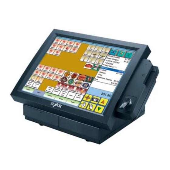
- Optional CD ROM Drive. - Countertop or Wall Mounting. - 6 x Serial Ports. - 1 x Parallel Port. - 1 x Network Port. - 6 x USB Ports. - Audio Output. - Easy Installation. - Easy Maintenance. Overview - ROBOT POS... - Page 10 Overview - ROBOT POS with Plastic cover Overview - SHOP POS...
-
Page 11: Lcd Angle Adjust
Overview - SCAN POS 2.1 LCD Angle Adjust In order to accommodate various operator preferences and lighting conditions, the ROBOT/SHOP/SCAN POS 3/4/5/6/7 is equipped with an operator tilt mechanism. Two buttons are located behind the upper left-hand edge of the Operator LCD. -
Page 12: Touch Screen
2.2 Touch Screen 2.2.1 Five Wire Resistive Touch Screen The touch screen is a 5 wire analog resistive, mounted on a chemically strengthened backing glass, with a resolution of 4096 x 4096 touch points. The ROBOT/SHOP/SCAN POS 3/4/6 is designed so that the application accepts all user input via the touch screen. -
Page 13: Hdd - Located Under The Machine
Caution: The HDD must be fitted with HDD Guides on both edges. Do Not insert the HDD into the POS without the HDD Guides installed or damage to the HDD and/or the POS will occur. The POS power must be switched off before inserting or to removing the 2.3.2 HDD - located under the machine. -
Page 14: Cd Rom
Caution: A. The POS power must be switched off before inserting or to removing the HDD 2.4 CD ROM A CD ROM is provided on the left-hand side of the ROBOT/SHOP/SCAN POS 3/4/5/6/7. The CD is inserted as shown below. Procedure 1 Press and release the CD ROM drawer button as indicated. -
Page 15: Connectors
Procedure 2 Gently pull the tray out until it reaches the end of its travel (Approx. 100mm) Insert the CD ROM (label side up). Push the CD tray back in until it can be heard to clock and the CD activates. Note: The CD will only work reliably when the LCD angle is in its maximum or minimum position. -
Page 16: Installation
3. INSTALLATION It is important that before installation the ROBOT/SHOP/SCAN POS 3/4/5/6/7 terminal's position and environment be considered. 3.1 Pre-installation Location Ensure that as with any computer equipment, the ROBOT/SHOP/SCAN POS 3/4/5/6/7 terminal in a clean and well-ventilated area away from direct sunlight Operator’s Comfort and Safety Operator comfort and safety should always be of the highest priority when deciding on the location and layout of the ROBOT/SHOP/SCAN POS 3/4/5/6/7... -
Page 17: Mounting
Mains AC Power Supply AC supply to the ROBOT/SHOP/SCAN POS 3/4/5/6/7 system should be a dedicated feed from the main switchboard. Do not connect any other equipment to this feed or damage to the POS terminal or its peripherals may result. - Page 18 2. Secure the mounting panel to the wall or counter top Counter Top Mounting...
- Page 19 Wall Mounting 3. Reposition the ROBOT/SHOP/SCAN POS 3/4/5/6/7 onto the mounting panel and ensure the locking tabs are pressed fully home (flush with the edge of the mounting panel). Mounting Panel Drilling Guide The mounting panel has 4 holes for mounting screws, these holes do not penetrate through the panel so must be completed by drilling through.
-
Page 20: Regular Maintenance
The location of peripherals should be decided upon, consideration for operator safety and comfort should be observed and the length and location of data cables to each peripheral device should be considered. The ROBOT/SHOP/SCAN POS 3/4/5/6/7 power supply is usually mounted underneath the countertop, ensure there is adequate area around the power supply for ventilation and it is oriented so that the cables, switches and indicators are easily accessible. - Page 21 touch screen and regularly clean with a soft slightly damp cloth. The activation pressure for the touch screen is 5.5 grams therefore only a light touch is required, never hit the screen or apply excessive pressure or permanent damage will occur. If there is difficulty activating the on screen buttons, the touch screen may need calibrating.
-
Page 22: Troubleshooting
5. TROUBLESHOOTING This section contains information that will help identify and correct problems that may arise with the ROBOT/SHOP/SCAN POS 3/4/5/6/7. If none of the recommendations in this chapter help identify and resolve the problem, contact with Service Dept. of Supplier. Before contacting, write down the exact syntax of any error messages that may be displayed, all symptoms of the problem and details of the system configuration. -
Page 23: Lcd Troubleshooting
An unrecoverable disk error occurs after using Turn off the Upper part and let it cool for a few minutes, the Upper part for a prolonged period of time check that the removable hard disk drive is firmly seated in the drive bay and nothing is obstructing the airflow into the Upper part or Power Supply (e.g. -
Page 24: Ram Troubleshooting
or power cable not connected or faulty, the Hard Disk "bay” is faulty or the motherboard is faulty. If the replacement drive works the original drive is faulty, partition and format the drive (using the DOS commands FDISK and FORMAT, described in the DOS manual). -
Page 25: Parallel Port Troubleshooting
When the Upper Part is turned on, the message Run the CMOS Setup utility, make sure the amount of "Invalid configuration information - please run base memory defined by the setup utility is correct, if not setup utility” is displayed, or the amount of base alter them. -
Page 26: Error Messages
5.7 Error Messages Error Message Possible Cause C: drive error Power off and reseat the hard disk drive. Run CMOS setup utility and ensure the correct hard disk type is entered (Auto Detect). If possible try another known working hard drive in the Upper Part If the new drive still does not work the problem will be internal to the Upper Part, either the internal HDD data or power cable not connected or faulty, the Hard Disk "bay"... -
Page 27: Caution
CAUTION If any abnormal power conditions or blackout occur during operation, immediately switch OFF the POS unit at the main power switch. Once normal power is restored, restart the POS unit. If the Keyboard Loopback Plug has been removed from the PS/2 keyboard port for any reason, reinstall to avoid keyboard error message during boot up.
Need help?
Do you have a question about the ROBOT POS and is the answer not in the manual?
Questions and answers