Advertisement
Advertisement
Table of Contents

Related Manuals for Schwinn Cadence Pro


Summary of Contents for Schwinn Cadence Pro
- Page 1 Group Cycle Computer Schwinn Cadence Pro Installation Instructions Console Installation & Instructions...
-
Page 2: Table Of Contents
Pairing Chest Transmitter to Console .........22 Personal Data Settings ...............23 Maintenance ..................24 Frequently Asked Questions ............25 Manufacturer: Core Health & Fitness 4400 NE 77th Ave, Ste 300 Vancouver, WA 98662 t:1-888-678-2476 www.SchwinnEducation.com Product Description: ® Group cycling computer for Schwinn indoor bikes. -
Page 3: Components In The Box
Installation & Instructions Components in the Box: DESCRIPTION QUANTITY n i l s t l DESCRIPTION s t l MAGNET MOUNT ................1 c i l MAGNET ....................1 Silicone Seal for Flat Bracket SPEED SENSOR ................1 COMPUTER CONSOLE ..............1 t t i RUBBER SHIMS ................4 Flywheel Transmitter Foam Holder MANUAL .....................1... -
Page 4: Specifications
Installation & Instructions Group Cycle Computer Console Specifications Features: • ANT+ interoperable 2.4Ghz wireless technology • Low power consumption for long battery life • Code memory during battery displacement • Triple data display; Cadence, Heart rate and Training data • Automatic Scan function •... -
Page 5: Certifications
Installation & Instructions Cadence Pro Computer Certifications Installation & Instructions Federal Communication Commission Interference Statement Group Cycle Computer Console This device complies with Part 15 of the FCC Rules. Operation is subject to the following two conditions: (1) this device may not cause harmful interference,... -
Page 6: Computer Bracket Mount Compatibility
Cadence Computer installed using the clamp bracket setup shown in (Fig.1). Schwinn ® IC Pro Fig. 1 The following products can have the Cadence Pro Computer in- stalled using the clamp bracket setup shown in (Fig 2). Schwinn AC Sport ® Schwinn ®... -
Page 7: Ic Pro
• Philips Screw Driver • Cadence Pro Computer Kit PN 740-8803 1.Take the Cadence Pro Computer and silicone seal (Fig. 1). Line up the silicone seal to the proper holes and apply it to the Cadence Pro Computer. (Fig. 2). - Page 8 3. Unscrew screws that hold the loops together (Fig 4). Fig 4 4. Wrap the loops around the handlebar. (Fig. 5 & Fig. 6). NOTE: If loops do not fit snugly around the handlebars, use the rubber shims to take up the slack. Fig.
- Page 9 6. Install the sensor, screw on the top and bottom screw (Fig. 8). 7. Peel off the adhesive patch (Fig. 9). Fig. 8 Fig. 9 8. Place plastic piece so that the curve at the bottom sits against the axle hub (Fig. 10). 9.
- Page 10 • Philips Screw Driver • Cadence Pro Computer Kit PN 740-8803 1.Take the Cadence Pro Computer and silicone seal (Fig. 1). Line up the silicone seal to the proper holes and apply it to the Cadence Pro Computer. (Fig. 2).
- Page 11 3. Unscrew screws that hold the loops together (Fig. 4) Fig 4 4. Insert clip on to the handlebar computer facing upwards (Fig. 5 & Fig. 6). NOTE: If loops do not fit snugly around bars, use the rubber shims to take up the slack. Fig.
- Page 12 6. Take the sensor, screw on the top and bottom screw (Fig. 8). Fig. 8 7. Peel off the adhesive patch that holds the magnet to the flywheel (Fig. 9). Place plastic piece so that the curve at the bottom sits against the axle hub (Fig. 10). Fig.
- Page 13 • Philips Screw Driver • Cadence Pro Computer Kit PN 740-8803 1.Take the Cadence Pro Computer and silicone seal (Fig. 1). Line up the silicone seal to the proper holes and apply it to the Cadence Pro Computer. (Fig. 2).
- Page 14 3. Wrap the loop around the handlebar computer facing upwards (Fig. 5 & Fig. 6). Fig. 5 Fig. 6 4. Install the sensor, screw on the bottom left screw (Fig. 7). Fig. 7 5. Set gear ratio, see pg 18. NOTE: The AC Performance Plus does not need any magnet installed because it’s pre-installed on the flywheel.
-
Page 15: Ac Sport
• Philips Screw Driver • Cadence Pro Computer Kit PN 740-8803 1.Take the Cadence Pro Computer and silicone seal (Fig. 1). Line up the silicone seal to the proper holes and apply it to the Cadence Pro Computer. (Fig. 2). - Page 16 3. Unscrew screws that hold the loops together (Fig. 4). Fig 4 4.Wrap the loops around the handlebar computer facing upwards (Fig. 5 & Fig. 6). Fig 5 Fig 6 5. Install the sensor, screw on the bottom left screw (Fig. 7). Fig.
-
Page 17: Set Gear Ratio
6. Peel off the adhesive patch from the RPM sensor magnet mount (Fig. 8). Fig 8 7. Place plastic piece so that the curve at the bottom sits against the axle hub (Fig. 9). Fig 9 8. Turn flywheel to verify the light on the sensor lights up. 9. - Page 18 For the AC Sport and ACPP Chain bike, select gear ratio 1:4.5. For the AC Sport and the ACPP Carbon Blue, select gear ratio 1:A.65. Schwinn Console (ZM6-S) Function Flow Chart (Engineering Mode) Date: 2015/2/25 Press any key before battery enter...
-
Page 19: Using The Console
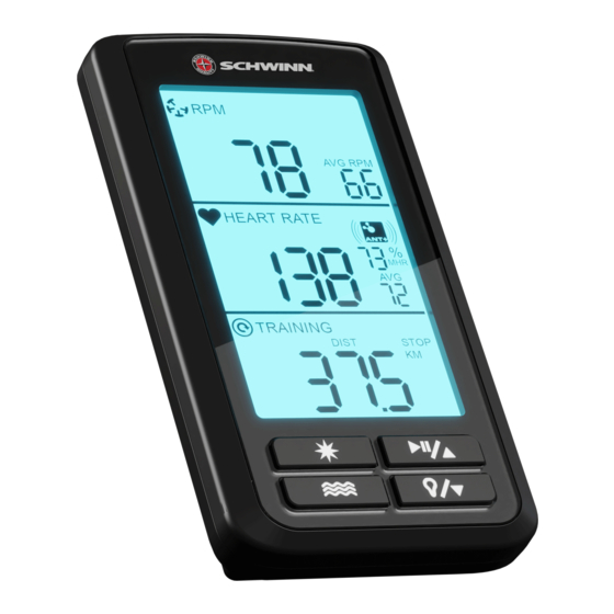
Installation & Instructions Instructions for Cadence Pro Computer Using The Console The top display (RPM) shows cadence in RPMs, average RPM (AVG RPM) and low battery indicator. Cadence in RPM is the speed of the pedal crank. The average rpm (AVG RPM) indicates the average speed in RPMs since the start of the exercise. - Page 20 Installation & Instructions To START and PAUSE the timer press the start/pause/up key To reset the timer press and hold the Mode key This can be done when displaying any TRAINING session. SCAN feature: To use the SCAN feature press the Mode key 3 times until (SCAN) appears in the TRAINING display.
-
Page 21: Pairing Flywheel Transmitter To Console
Installation & Instructions Pairing Flywheel Transmitter to Console Begin with one battery removed from the console. Insert the battery while pressing and holding any of the four keys on the front of the console. The display will now show the maintenance screen. Press the Set key which will show (CAD) in the middle display and (E01) in the top display. -
Page 22: Pairing Chest Transmitter To Console
Installation & Instructions Pairing Chest Transmitter to Console From sleep mode press any key, this will activate the console. Press and hold Set key this will display heart rate and ANT+ symbol. For automatic pairing press Mode Key this will display a four digit code below the stated heart rate. -
Page 23: Personal Data Settings
Installation & Instructions Personal Data Settings and Chest Transmitter Pairing The product comes with three default settings: Age (AGE): 30 Ambient heart rate* (AHR): 70 bpm Weight (WT) Kg/Ibs): 70kg (154 Ibs) Press Set key to set age (AGE) adjust using the up key or down key. -
Page 24: Maintenance
Installation & Instructions Maintenance We strongly recommend performing the regular daily, weekly and monthly preventive maintenance routines outlined below. If any items need re- placement contact Customer Support Department at 1-888-678-2476. D= Daily W= Weekly M= Monthly Procedure Daily maintenance of the computer will determine its life of the computer by how consistently it is performed. -
Page 25: Frequently Asked Questions
Installation & Instructions Frequently Asked Questions: What are the Personal Data Settings for use at HOME and in a CLUB? • HOME setting should be followed using the procedures indicated starting on page 23. Imputing you AGE, AHR and WT will give you the most accu- rate estimate of caloric expenditure on the bike. - Page 26 Installation & Instructions The computer is not picking up my heart rate Make sure that the heart rate strap is fitted snuggly at the bottom of your ribcage and that the sensors are slightly moistened. The battery in the strap might be low, try another strap. ...
- Page 28 For more information visit SchwinnEquipment.com or call 1-888-678-2476 620-8292 Rev A, May 2015 Core Health & Fitness...
Need help?
Do you have a question about the Cadence Pro and is the answer not in the manual?
Questions and answers