M-Audio 10 IN 10 OUT PCI DIGITAL RECORDING SYSTEM WITH S/PDIF DELTA 1010 User Manual
10 in 10 out pci digital recording system with s/pdif
Hide thumbs
Also See for 10 IN 10 OUT PCI DIGITAL RECORDING SYSTEM WITH S/PDIF DELTA 1010:
- Quick start manual (10 pages) ,
- User manual (6 pages) ,
- Manual (52 pages)
Table of Contents

Related Manuals for M-Audio 10 IN 10 OUT PCI DIGITAL RECORDING SYSTEM WITH S/PDIF DELTA 1010


Summary of Contents for M-Audio 10 IN 10 OUT PCI DIGITAL RECORDING SYSTEM WITH S/PDIF DELTA 1010
-
Page 1: User Guide
10 in 10 out PCI Digital Recording System with S/PDIF User Guide... -
Page 2: Table Of Contents
Introduction ......3 What’s in the Box? ......3 About the Delta 1010 Digital Recording System . -
Page 3: Introduction
Delta 1010 audio interface. Delta 1010 is the top product in M-Audio’s line of award winning “Delta” digital recording systems and has helped set the standard for the solid hardware design and robust driver technology found in other members of the Delta family. -
Page 4: About The Delta 1010 Digital Recording System
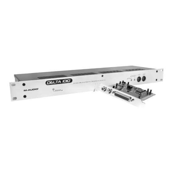
elta 1010 is a professional audio interface with a total of 10 inputs and 10 outputs. The interface features eight 1/4” balanced/unbalanced analog inputs and outputs as well as a pair of coaxial (RCA) S/PDIF I/O. Delta 1010 can create pristine 24-bit recordings at sampling rates of up to 96 kHz. -
Page 5: Product Features & Specifications
Delta 1010 User Guide Product Features & Specifications 10-input, 10-output recording interface < Supports up to 24-bit, 96kHz operation < PCI host card with DSP for digital mixing < Sturdy rack-mounted I/O interface < Eight balanced/unbalanced analog inputs and outputs on 1/4” connectors with <... -
Page 6: Minimum System Requirements
< 256 MB RAM < *M-Audio suggests that you also check the minimum system requirements for your software, as they may be greater than Delta 1010’s requirements. **Home and Professional Edition only. Windows Media Center Edition is not currently supported †G3/G4 accelerator cards not supported. -
Page 7: Rack Unit Back Panel
MIDI Input Jack (MIDI In): This standard 5-pin MIDI connector accepts signals from any MIDI compatible device such as a keyboard or control surface. MIDI Output Jack (MIDI Out): This standard 5-pin MIDI connector transmits signals to any MIDI compatible device such as a synthesizer, sound module, or drum machine. -
Page 8: Pci Host Adapter Card
Signal-Level +4/-10 Switch: This button sets the operating signal level for each analog input and output channel. When this switch is in the out position, its associated channel will operate at the professional +4dBu standard; when the switch is pressed, the channel will operate at -10dBV. About the +4/10 button: The +4dBu standard is used by most mixers, preamplifiers, and other professional audio devices with balanced outputs. - Page 9 (printer port) of a computer. This type of cable is commonly available through computer and professional audio stores and M-Audio has successfully tested Delta 1010 with cables up to 25 feet in length. If the supplied...
-
Page 10: Delta System Overview
To record a microphone, you must first pass the microphone signal through a microphone preamplifier (such as the M-Audio TAMPA) and connect the preamplified line-level or S/PDIF output to the input of the Delta 1010. -
Page 11: The Patchbay / Router
Delta 1010 User Guide The Patchbay / Router In addition to the built-in Monitor Mixer, Delta 1010 also provides virtual signal patching and routing capabilities. This “Patchbay/Router” is accessed through the Control Panel software and allows a variety of sources (including your music software, the analog and digital inputs of the interface, or the Monitor Mixer output) to be linked to various physical outputs on the interface. -
Page 12: Using Delta 1010 With Your Audio Software
Clock Source to S/PDIF and make sure that the connected source device is configured as clock master. Please see the Digital Synchronization and Multi-Device Setup Guide found at http://www.m-audio.com for more information. *“Delta 1010 11/12” is the output of the hardware Monitor Mixer on the PCI card and can be selected if you wish to record the combined physical and virtual inputs (audio returning from your recording software) of the Monitor Mixer. -
Page 13: Audio Outputs
Audio Outputs: The following list should help you associate the output names displayed by your software with Delta 1010’s corresponding physical outputs: Display Name Delta 1010 1/2 Delta 1010 3/4 Delta 1010 5/6 Delta 1010 7/8 Delta 1010 9/10 NOTE: There may be slight variations in the naming of outputs when using certain audio applications. -
Page 14: Control Panel Software
User Guide to learn about the Mac OS X Control Panel. To access the Delta Control Panel in Windows, double-click the M-Audio icon in the system tray, or click Start > Control Panel and double-click the Delta 1010 Control Panel icon. - Page 15 Monitor Mixer is the first tab that appears when the Control Panel is opened. This tab controls the digital mixer built into the Delta 1010 PCI Host Adapter card and has the following controls and indicators: LEVEL FADERS: Each volume fader is controlled by dragging the vertical <...
- Page 16 MIXER INPUTS: The Mixer Input channels are found to the right of the Master < Volume section. These channels receive audio directly from Delta 1010’s analog and digital inputs as well as from the outputs of your audio software. This allows you to mix your incoming signals with your previously recorded tracks to create a hardware monitor mix that is virtually free of the delay (or “latency”) that is inherent in all software-based digital mixing systems.
-
Page 17: Patchbay/Router Tab
MUTE: Every Monitor Mixer channel has a “Mute” checkbox. When this box < is checked, its associated channel will not be routed to the stereo output and will not be heard in the monitor mix. When the box is unchecked, its associated channel will be routed to the mixer’s output. -
Page 18: Hardware Settings Tab
S/PDIF In: This input corresponds to the S/PDIF input. < S/PDIF In (L/R Rev.): This corresponds to the S/PDIF input but swaps the left < and right channels. H/W In 1/2 through 7/8: These inputs correspond to the hardware analog <... - Page 19 For more information about Clocking, please see Appendix A: Clocking at the end of this guide and/or read the Digital Synchronization and Multi-Device Setup Guide found on http://www.m-audio.com.. CODEC SAMPLE RATE: This section lets you select the sampling rate of the <...
- Page 20 S/PDIF SAMPLE RATE: When using the S/PDIF < input as your master clock source, use these radio buttons to indicate the expected incoming sample rate. Your selection here will be the only sample rate available to your audio software. This ensures that recordings will be made at the proper rate.
- Page 21 See Appendix A: Clocking of this guide to learn more about clocking and synchronization. To learn more about multi-card operation, see the Digital Synchronization and Multi-Device Setup Guide found on www.m-audio.com. DMA BUFFER SIZES: This drop-down menu sets the size of the input and <...
-
Page 22: S/Pdif Tab
To find your system’s optimum buffer size setting, begin with a high setting and gradually reduce the size until you begin to hear glitches in your audio. Then raise the buffer size setting until these glitches disappear. • ASIO Options: Some ASIO compliant applications (such as Steinberg Cubase or Nuendo) allow you to control some of the Monitor Mixer’s and Patchbay/Router’s settings through the Delta 1010’s ASIO driver. - Page 23 Delta 1010 User Guide DIGITAL INPUT: This section of the Control Panel displays the current S/PDIF < input status. • S/PDIF Signal: When Delta 1010 is receiving a valid S/PDIF signal, “Valid Input Detected” is displayed. If no signal is present or the incoming signal is invalid, the “Invalid or Not Present”...
- Page 24 CONSUMER FORMAT ADVANCED SETTINGS: The following settings < appear when “Consumer” has been selected in the Digital Output Format section and the Advanced Settings box has been checked: • Copy Mode: These radio buttons control the Serial Copy Management System (SCMS) part of the S/PDIF subcode—a reserved part of the S/PDIF digital stream that is...
-
Page 25: Bass Management Tab
LFE routing options, speaker distance settings, etc. Please download the Delta Bass Management Addendum from the M-Audio website at www.m-audio.com for a full description of the features available in this tab. Delta 1010 User Guide... -
Page 26: About Tab
About Tab The “About” tab displays driver and Control Panel version numbers and provides a convenient link to the M-Audio website. Additional Control Panel Features The Delta 1010 Control Panel has several “global” features that apply to the entire Control Panel. They are as follows: SAVE, DELETE, LOAD: The Control Panel always retains the last settings <... -
Page 27: Control Panel Software For Mac Os X
User Guide to learn about the Windows XP Control Panel. The Mac OS X Control Panel can be accessed by double-clicking the M-Audio icon in the Applications folder or by selecting the M-Audio Delta icon in System Preferences >... - Page 28 Monitor Mixer is the first tab that appears when the Control Panel is opened. This tab controls the digital mixer built into the Delta 1010 PCI Host Adapter card and has the following controls and indicators: LEVEL FADERS: Each volume fader is controlled by dragging the vertical <...
- Page 29 Delta 1010 User Guide generally not enter into the red zone. Technically, your signal may enter into the red zone without resulting in distortion but this not generally recommended since it leaves very little headroom. In other words, one loud note during a performance or mix may result in a severely distorted recording or mix.
-
Page 30: Patch Bay Tab
SOLO: Each mixer input channel features a “Solo” checkbox. When a channel’s < Solo box is checked, all other channels will be temporarily muted and only the “soloed” channel will be heard. Deactivating all solo boxes will return all input channels to their previous mute/unmute states. -
Page 31: Hardware Settings Tab
The input sources are described below: • Software Out 1/2 through 7/8: These inputs correspond to the outputs of your audio software. • Monitor Mixer: This input corresponds to the output of the Delta 1010 Monitor Mixer. This audio source can only be routed to analog outputs 1-2 and/or the S/PDIF output. - Page 32 For more information about Clocking, please see Appendix A: Clocking at the end of this guide and/or read the Digital Sync and Multi-Device Setup Guide found on www.m-audio.com. Delta 1010 User Guide...
-
Page 33: S/Pdif Tab
(i.e., when you are using multiple Delta cards in one computer). Please see the Digital Synchronization and Multi-Device Setup Guide found on http://www.m-audio.com for more information. S/PDIF Tab This tab configures a variety of parameters relating to the operation of the S/PDIF output port located on the PCI Host Adapter card. - Page 34 • Advanced Settings: Selecting this check box reveals several advanced features at the bottom of the S/PDIF tab. Note that your selection of “Consumer” or “Professional” (see above) will determine the advanced options that will be displayed when this box is checked. •...
- Page 35 Delta 1010 User Guide Original (Copy Permitted) – This setting indicates that the audio stream currently playing is a “master” recording and that the source material may be copied by a recording device. 1st Generation – This setting indicates that the source material is a first generation copy of the master recording.
-
Page 36: About Tab
To learn more about this, refer to the Clock Synchronization description in the Hardware Settings Tab section of this chapter and/or read the Digital Synchronization and Multi-Device Setup Guide found on www.m-audio.com. Delta 1010 User Guide... - Page 37 Delta 1010 User Guide SMALL VU: Clicking this button will display all of the Control Panel’s VU meters < in a miniature screen. This screen is intended to help recording engineers by displaying all input and output levels at a quick glance. Note that this window does not have any controls;...
-
Page 38: Troubleshooting
If these steps do not resolve your problems, please see the Support > Knowledge Base page on www.m-audio.com for additional information. Possible Cause 4: Card and your computer is powered on, but the Power LED is not illuminated, shut down your computer and double-check that the host cable is connected properly. - Page 39 Possible Cause 5: but your audio application’s input meters are not moving, then Delta 1010’s Patchbay/Router and/or your audio application may not be configured properly. • Refer to the Patchbay/Router Tab section of this User Guide to learn more about how to configure Delta 1010’s Patchbay/Router. •...
- Page 40 Delta 1010 User Guide Problem: Clicks, pops, and other glitches in audio streams. Possible Cause 1: Input levels are too loud and are resulting in clipping or distortion. Lower the source’s output level. If you are using a microphone preamplifier, reduce its gain to avoid overloading the interface. The meter display in the Control Panel can be used as a visual aid to help you set optimal input levels.
-
Page 41: Technical Specifications
Delta 1010 User Guide Analog Audio Peak Analog Input Signal: Peak Analog Output Signal: Dynamic Range: THD (at 0dBFS): Frequency Response: Input Impedance: Input Connectors: Output Connectors: Digital Audio Digital Input Format: Digital Input Sample Rate: Digital Output Format: Digital Output Sample Rate: Word Clock Input Rate: Word Clock Output Rate: Technical Specifications... -
Page 42: Technical Info
In such case, unplug the unit and plug it in again to restore normal operation. NOTE: Your M-Audio product has been tested to comply with FCC Standards FOR HOME OR OFFICE USE. Modifications not authorized by the manufacturer may void users authority to operate this device. -
Page 43: Appendix
S/PDIF or Word Clock connectors, set the “Clock Source” parameter to “Internal Xtal” (“Internal Crystal” for Mac OS X users). NOTE: If you are using multiple Delta cards in the same system, please also see the Digital Synchronization and Multi-Device Setup Guide found on www.m-audio.com. -
Page 44: Warranty Terms And Registration
Warranty Terms and Registration Warranty Terms M-Audio warrants products to be free from defects in materials and workmanship, under normal use and provided that the product is owned by the original, registered user. Visit www.m-audio.com/warranty for terms and limitations applying to your specific product. -
Page 45: Technical Support
M-Audio USA 5795 Martin Rd., Irwindale, CA 91706 Technical Support web: www.m-audio.com/tech tel (pro products): (626) 633-9055 tel (consumer products): (626) 633-9066 fax (shipping): (626) 633-9032 Sales e-mail: sales@m-audio.com tel: 1-866-657-6434 fax: (626) 633-9070 www.m-audio.com M-Audio U.K. Floor 6, Gresham House, 53 Clarenden Road, Watford...
Need help?
Do you have a question about the 10 IN 10 OUT PCI DIGITAL RECORDING SYSTEM WITH S/PDIF DELTA 1010 and is the answer not in the manual?
Questions and answers