Table of Contents
Advertisement
Quick Links
SPLIT-TYPE, HEAT PUMP AIR CONDITIONERS
SPLIT-TYPE, AIR CONDITIONERS
TECHNICAL & SERVICE MANUAL
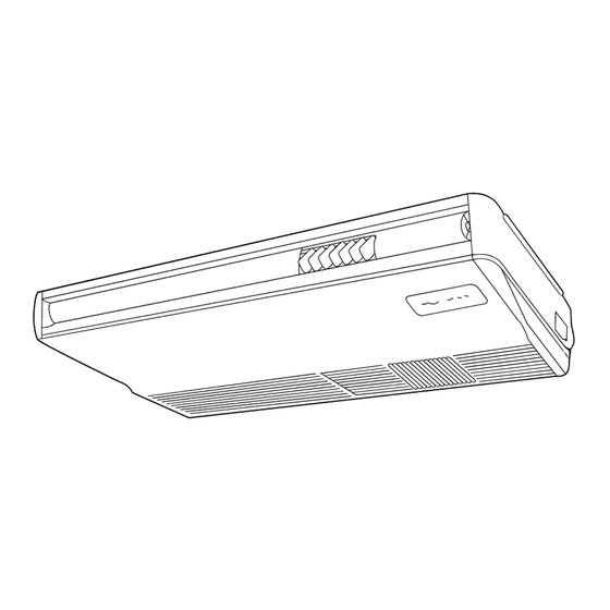
Ceiling Suspended
Series PCA
Indoor unit
[Model names]
PCA-RP2GA
PCA-RP2.5GA
PCA-RP3GA
PCA-RP4GA
PCA-RP5GA
PCA-RP6GA
INDOOR UNIT
CENTRALLY CONTROLLED
ON OFF
CLOCK
CHECK
˚C
STAND BY
ERROR CODE
DEFROST
TEMP.
REMOTE CONTROLLER
[Service Ref.]
PCA-RP2GA
PCA-RP2.5GA
PCA-RP3GA
PCA-RP4GA
PCA-RP5GA
PCA-RP6GA
Model name
indication
1Hr.
˚C
FILTER
CHECK MODE
TEST RUN
NOT AVAILABLE
FUNCTION
ON/OFF
R407C/R410A
CONTENTS
1.
2. SAFETY PRECAUTION ···································3
3. PART NAMES AND FUNCTIONS····················7
4. SPECIFICATIONS ············································9
5. DATA·······························································18
6. OUTLINES AND DIMENSIONS ·····················50
7. WIRING DIAGRAM············································54
8. REFRIGERANT SYSTEM DIAGRAM ··················55
9. TROUBLESHOOTING ···································56
10. DISASSEMBLY PROCEDURE ······················66
11. PARTS LIST ···················································71
12. OPTIONAL PARTS ········································78
2004
No. OC311
NOTE:
• This manual does not cover
outdoor units. When serving
them, please refer to the
service manual No.OC261
REVISED EDITION-B,
OC285, OC294 REVISED
EDITION-B, OC298 and
this manual in a set.
··2
Advertisement
Table of Contents
Troubleshooting

Related Manuals for Mitsubishi Electric PCA-RP2GA


Summary of Contents for Mitsubishi Electric PCA-RP2GA
-
Page 1: Table Of Contents
TECHNICAL & SERVICE MANUAL R407C/R410A Ceiling Suspended Series PCA Indoor unit NOTE: [Model names] [Service Ref.] • This manual does not cover PCA-RP2GA outdoor units. When serving PCA-RP2GA them, please refer to the PCA-RP2.5GA service manual No.OC261 PCA-RP2.5GA REVISED EDITION-B, PCA-RP3GA... -
Page 2: Combination Of Indoor And Outdoor Units
COMBINATION OF INDOOR AND OUTDOOR UNITS (R410A Inverter) Outdoor unit [OC294 REVISED EDITION-B] Heat pump type Indoor unit PUHZ-RP 2VHA 2.5VHA 3VHA 4VHA 5VHA 6VHA 4VHA 5VHA 6VHA PCA-RP2GA — — — — — PCA-RP2.5GA — — — — — PCA-RP3GA — —... -
Page 3: Safety Precaution
SAFETY PRECAUTION CAUTIONS RELATED TO NEW REFRIGERANT Cautions for units utilising refrigerant R407C Do not use the existing refrigerant piping. Use liquid refrigerant to charge the system. The old refrigerant and lubricant in the existing piping If gas refrigerant is used to seal the system, the composition contains a large amount of chlorine which may cause the of the refrigerant in the cylinder will change and performance lubricant deterioration of the new unit. - Page 4 [3] Service tools Use the below service tools as exclusive tools for R407C refrigerant. Tool name Specifications Gauge manifold ·Only for R407C. ·Use the existing fitting SPECIFICATIONS. (UNF7/16) ·Use high-tension side pressure of 3.43MPa·G or over. Charge hose ·Only for R407C. ·Use pressure performance of 5.10MPa·G or over.
- Page 5 CAUTIONS RELATED TO NEW REFRIGERANT Cautions for units utilising refrigerant R410A Use new refrigerant pipes. Do not use refrigerant other than R410A. In case of using the existing pipes for R22, be careful with If other refrigerant (R22 etc.) is used, chlorine in refrige- the followings.
- Page 6 Unit Gravimeter [3] Service tools Use the below service tools as exclusive tools for R410A refrigerant. Specifications Gauge manifold ·Only for R410A ·Use the existing fitting specifications . (UNF1/2) ·Use high-tension side pressure of 5.3MPa·G or over. Charge hose ·Only for R410A ·Use pressure performance of 5.09MPa·G or over.
-
Page 7: Part Names And Functions
PART NAMES AND FUNCTIONS Indoor Unit Left/right guide vanes Change the direction of airflow from the horizontal blower. Air outlet Long-life filter Removes dust and foreign matter from air coming in through the grille (Recommended cleaning interval : Approx, every 2,500 operating hours) Air intake Up/down guide vanes Intake grille... -
Page 8: Operation Lamp
Display In this display example on the bot- CENTRALLY CLOCK display tom left, a condition where all dis- CONTROLLED display play lamps light is shown for expla- The current time , start time and stop time can be displayed in ten second nation purposes although this differs This indicates when the unit is con- intervals by pressing the time switch... -
Page 9: Specifications
SPECIFICATIONS 4-1. Heat pump type (1) Service Ref. PCA-RP2GA Item Function Cooling Heating Btu/h 16,000 18,800 Capacity 4,700(2,300~5,400) 5,500(2,500~6,600) 1.67 1.71 Total input Service Ref. PCA-RP2GA Power supply(phase, cycle, voltage) Single phase, 50Hz, 220-230-240V 0.09 Input 0.09 Running current 0.41 0.41... - Page 10 Service Ref. PCA-RP3GA Item Function Cooling Heating Btu/h 24,200 27,300 Capacity 7,100(3,300~8,100) 8,000(3,500~10,200) 2.14 2.43 Total input Service Ref. PCA-RP3GA Power supply(phase, cycle, voltage) Single phase, 50Hz, 220-230-240V 0.12 Input 0.12 Running current 0.53 0.53 Starting current 1.27 1.27 External finish Munsell 0.70Y 8.59/0.97 Heat exchanger Plate fin coil...
- Page 11 Service Ref. PCA-RP5GA Item Cooling Heating Function 42,700 Btu/h 47,800 12,500(6,000~14,000) 14,000(6,000~16,000) Capacity PUHZ-RP5VHA PUHZ-RP5VHA 12,500(5,500~14,000) 14,000(5,000~16,000) Total input 3.89 4.34 Service Ref. PCA-RP5GA Power supply(phase, cycle, voltage) Single phase, 50Hz, 220-230-240V Input 0.22 0.22 Running current 1.01 1.01 Starting current 2.20 2.20 External finish...
- Page 12 4-2. Heat pump type (2) Service Ref. PCA-RP2GA Item Function Cooling Heating Btu/h 18,300 21,200 Capacity 5,350 6,200 2.35 Total input 2.36 Service Ref. PCA-RP2GA Power supply(phase, cycle, voltage) Single phase, 50Hz, 220-230-240V Input 0.09 0.09 Running current 0.41 0.41 1.20...
- Page 13 Service Ref. PCA-RP3GA Item Cooling Function Heating 25,400 Btu/h 31,200 Capacity 7,450 9,150 Total input 3.37 3.48 Service Ref. PCA-RP3GA Power supply(phase, cycle, voltage) Single phase, 50Hz, 220-230-240V Input 0.12 0.12 Running current 0.53 0.53 Starting current 1.27 1.27 External finish Munsell 0.70Y 8.59/0.97 Heat exchanger Plate fin coil...
- Page 14 Service Ref. PCA-RP5GA Item Function Cooling Heating Btu/h 42,000 50,500 Capacity 12,300 14,800 4.91 5.11 Total input Service Ref. PCA-RP5GA Power supply(phase, cycle, voltage) Single phase, 50Hz, 220-230-240V Input 0.22 0.22 Running current 1.01 1.01 Starting current 2.20 2.20 External finish Munsell 0.70Y 8.59/0.97 Heat exchanger Plate fin coil...
- Page 15 4-3. Cooling type Service Ref. PCA-RP2GA Item Function Cooling Btu/h 18,300 Capacity 5,350 2.35 Total input Service Ref. PCA-RP2GA Power supply(phase, cycle, voltage) Single phase, 50Hz, 220-230-240V 0.09 Input Running current 0.41 Starting current 1.20 External finish Munsell 0.70Y 8.59/0.97...
- Page 16 Service Ref. PCA-RP3GA Item Function Cooling Btu/h 25,400 Capacity 7,450 3.37 Total input Service Ref. PCA-RP3GA Power supply(phase, cycle, voltage) Single phase, 50Hz, 220-230-240V Input 0.12 Running current 0.53 Starting current 1.27 External finish Munsell 0.70Y 8.59/0.97 Heat exchanger Plate fin coil Fan(drive) x No.
- Page 17 Service Ref. PCA-RP5GA Item Function Cooling Btu/h 42,000 Capacity 12,300 4.91 Total input Service Ref. PCA-RP5GA Power supply(phase, cycle, voltage) Single phase, 50Hz, 220-230-240V Input 0.22 Running current 1.01 Starting current 2.20 External finish Munsell 0.70Y 8.59/0.97 Heat exchanger Plate fin coil Fan(drive) x No.
-
Page 18: Data
DATA 5-1. PERFORMANCE DATA (230V) COOLING CAPACITY<1> PCA-RP2GA / PUHZ-RP2VHA (230V) Outdoor intake air D.B.(°C) Indoor Indoor Intake air Intake air SHC(W) D.B.(°C) W.B.(°C) SHC(W) P.C. SHC(W) P.C. P.C. 0.66 2885 0.66 4653 3071 1.34 4512 2978 0.66 1.41 4371 1.49... - Page 19 COOLING CAPACITY<2> PCA-RP2GA / PUHZ-RP2VHA (230V) Outdoor intake air D.B.(°C) Indoor Indoor Intake air Intake air SHC(W) D.B.(°C) W.B.(°C) SHC(W) P.C. SHC(W) P.C. P.C. 0.66 2513 0.66 4183 2761 1.60 3995 2637 0.66 1.72 3807 1.86 0.54 2208 0.54 4512 2436 1.64...
- Page 20 COOLING CAPACITY<3> PCA-RP2.5GA / PUHZ-RP2.5VHA (230V) Outdoor intake air D.B.(°C) Indoor Indoor Intake air Intake air SHC(W) D.B.(°C) W.B.(°C) SHC(W) P.C. SHC(W) P.C. P.C. 3962 0.71 0.71 5940 4217 1.30 5760 4090 0.71 1.38 5580 1.46 0.59 3522 0.59 6360 3752 1.33 6180...
- Page 21 COOLING CAPACITY<4> PCA-RP2.5GA / PUHZ-RP2.5VHA (230V) Outdoor intake air D.B.(°C) Indoor Indoor Intake air Intake air SHC(W) D.B.(°C) W.B.(°C) SHC(W) P.C. SHC(W) P.C. P.C. 0.71 3451 0.71 5340 3791 1.56 5100 3621 0.71 1.68 4860 1.82 3080 0.59 0.59 5760 3398 1.61 5580...
- Page 22 COOLING CAPACITY<5> PCA-RP3GA / PUHZ-RP3VHA (230V) Outdoor intake air D.B.(°C) Indoor Indoor Intake air Intake air SHC(W) D.B.(°C) W.B.(°C) SHC(W) P.C. SHC(W) P.C. P.C. 0.64 4226 0.64 7029 4499 1.71 6816 4362 0.64 1.81 6603 1.92 3674 0.52 0.52 7526 3914 1.74 7313...
- Page 23 COOLING CAPACITY<6> PCA-RP3GA / PUHZ-RP3VHA (230V) Outdoor intake air D.B.(°C) Indoor Indoor Intake air Intake air SHC(W) D.B.(°C) W.B.(°C) SHC(W) P.C. SHC(W) P.C. P.C. 3681 0.64 0.64 6319 4044 2.05 6035 3862 0.64 2.20 5751 2.39 0.52 3212 0.52 6816 3544 2.11 6603...
- Page 24 COOLING CAPACITY<7> PCA-RP4GA / PUHZ-RP4VHA PUHZ-RP4VHA (230V) Outdoor intake air D.B.(°C) Indoor Indoor Intake air Intake air SHC(W) D.B.(°C) W.B.(°C) SHC(W) P.C. SHC(W) P.C. P.C. 0.65 6045 0.65 9900 6435 2.34 9600 6240 0.65 2.47 9300 2.61 0.53 5274 0.53 10600 5618 2.38...
- Page 25 COOLING CAPACITY<8> PCA-RP4GA / PUHZ-RP4VHA PUHZ-RP4VHA (230V) Outdoor intake air D.B.(°C) Indoor Indoor Intake air Intake air SHC(W) D.B.(°C) W.B.(°C) SHC(W) P.C. SHC(W) P.C. P.C. 0.65 5265 0.65 8900 5785 2.80 8500 5525 0.65 3.01 8100 3.26 0.53 4611 0.53 9600 5088 2.88...
- Page 26 COOLING CAPACITY<9> PCA-RP5GA / PUHZ-RP5VHA PUHZ-RP5VHA (230V) Outdoor intake air D.B.(°C) Indoor Indoor Intake air Intake air SHC(W) D.B.(°C) W.B.(°C) SHC(W) P.C. SHC(W) P.C. P.C. 0.67 7789 0.67 12375 8291 3.11 12000 8040 0.67 3.29 11625 3.48 0.55 6841 0.55 13250 7288 3.17...
- Page 27 COOLING CAPACITY<10> PCA-RP5GA / PUHZ-RP5VHA PUHZ-RP5VHA (230V) Outdoor intake air D.B.(°C) Indoor Indoor Intake air Intake air SHC(W) D.B.(°C) W.B.(°C) SHC(W) P.C. SHC(W) P.C. P.C. 0.67 6784 0.67 11125 7454 3.73 10625 7119 0.67 4.01 10125 4.34 0.55 5981 0.55 12000 6600 3.83...
- Page 28 COOLING CAPACITY<11> PCA-RP6GA / PUHZ-RP6VHA PUHZ-RP6VHA (230V) Outdoor intake air D.B.(°C) Indoor Indoor Intake air Intake air SHC(W) D.B.(°C) W.B.(°C) SHC(W) P.C. SHC(W) P.C. P.C. 0.64 8333 0.64 13860 8870 3.97 13440 8602 0.64 4.19 13020 4.44 0.52 7244 0.52 14840 7717 4.04...
- Page 29 COOLING CAPACITY<12> PCA-RP6GA / PUHZ-RP6VHA PUHZ-RP6VHA (230V) Outdoor intake air D.B.(°C) Indoor Indoor Intake air Intake air SHC(W) D.B.(°C) W.B.(°C) SHC(W) P.C. SHC(W) P.C. P.C. 0.64 7258 0.64 12460 7974 4.76 11900 7616 0.64 5.11 11340 5.53 0.52 6334 0.52 13440 6989 4.89...
- Page 30 COOLING CAPACITY<13> PCA-RP2GA / PUH-P2VGAA PUH-P2VGAA.UK PUH-P2YGAA.UK PUH-P2VGAA .UK PUH-P2YGAA PU-P2VGAA PU-P2VGAA.UK PU-P2YGAA.UK (230V) PU-P2VGAA PU-P2YGAA Outdoor intake air D.B.(°C) Indoor Indoor Intake air Intake air SHC(W) D.B.(°C) W.B.(°C) SHC(W) P.C. SHC(W) P.C. P.C. 3085 0.62 0.62 5297 3284 1.88...
- Page 31 COOLING CAPACITY<14> PCA-RP2GA / PUH-P2VGAA PUH-P2VGAA.UK PUH-P2YGAA.UK PUH-P2VGAA .UK PUH-P2YGAA PU-P2VGAA PU-P2VGAA.UK PU-P2YGAA.UK (230V) PU-P2VGAA PU-P2YGAA Outdoor intake air D.B.(°C) Indoor Indoor Intake air Intake air SHC(W) D.B.(°C) W.B.(°C) SHC(W) P.C. SHC(W) P.C. P.C. 0.62 2687 0.62 4762 2952 2.26...
- Page 32 COOLING CAPACITY<15> PCA-RP2.5GA / PUH-P2.5VGAA PUH-P2.5VGAA.UK PUH-P2.5YGAA.UK PUH-P2.5VGAA PUH-P2.5YGAA PU-P2.5VGAA PU-P2.5VGAA.UK PU-P2.5YGAA.UK (230V) PU-P2.5VGAA PU-P2.5YGAA Outdoor intake air D.B.(°C) Indoor Indoor Intake air Intake air SHC(W) D.B.(°C) W.B.(°C) SHC(W) P.C. SHC(W) P.C. P.C. 0.65 3990 0.65 6534 4247 2.10 6336 4118 0.65 2.21...
- Page 33 COOLING CAPACITY<16> PCA-RP2.5GA / PUH-P2.5VGAA PUH-P2.5VGAA.UK PUH-P2.5YGAA.UK PUH-P2.5VGAA PUH-P2.5YGAA PU-P2.5VGAA PU-P2.5VGAA.UK PU-P2.5YGAA.UK (230V) PU-P2.5VGAA PU-P2.5YGAA Outdoor intake air D.B.(°C) Indoor Indoor Intake air Intake air SHC(W) D.B.(°C) W.B.(°C) SHC(W) P.C. SHC(W) P.C. P.C. 0.65 3475 0.65 5874 3818 2.52 5610 3647 0.65 2.70...
- Page 34 COOLING CAPACITY<17> PCA-RP3GA / PUH-P3VGAA PUH-P3YGAA PUH-P3VGAA.UK PUH-P3YGAA.UK PUH-P3VGAA .UK PUH-P3YGAA PU-P3VGAA PU-P3YGAA PU-P3VGAA.UK PU-P3YGAA.UK (230V) PU-P3VGAA PU-P3YGAA Outdoor intake air D.B.(°C) Indoor Indoor Intake air Intake air SHC(W) D.B.(°C) W.B.(°C) SHC(W) P.C. SHC(W) P.C. P.C. 4365 0.63 0.63 7376 4647 2.70 7152...
- Page 35 COOLING CAPACITY<18> PCA-RP3GA / PUH-P3VGAA PUH-P3YGAA PUH-P3VGAA.UK PUH-P3YGAA.UK PUH-P3VGAA .UK PUH-P3YGAA PU-P3VGAA PU-P3YGAA PU-P3VGAA.UK PU-P3YGAA.UK (230V) PU-P3VGAA PU-P3YGAA Outdoor intake air D.B.(°C) Indoor Indoor Intake air Intake air SHC(W) D.B.(°C) W.B.(°C) SHC(W) P.C. SHC(W) P.C. P.C. 0.63 3802 0.63 6631 4177 3.24 6333...
- Page 36 COOLING CAPACITY<19> PCA-RP4GA / PUH-P4YGAA PUH-P4VGAA.UK PUH-P4YGAA.UK PUH-P4VGAA .UK PUH-P4YGAA PU-P4YGAA PU-P4VGAA.UK PU-P4YGAA.UK (230V) PU-P4VGAA PU-P4YGAA Outdoor intake air D.B.(°C) Indoor Indoor Intake air Intake air SHC(W) D.B.(°C) W.B.(°C) SHC(W) P.C. SHC(W) P.C. P.C. 0.66 5892 0.66 9504 6273 2.90 9216 6083 0.66...
- Page 37 COOLING CAPACITY<20> PCA-RP4GA / PUH-P4YGAA PUH-P4VGAA.UK PUH-P4YGAA.UK PUH-P4VGAA .UK PUH-P4YGAA PU-P4YGAA PU-P4VGAA.UK PU-P4YGAA.UK (230V) PU-P4VGAA PU-P4YGAA Outdoor intake air D.B.(°C) Indoor Indoor Intake air Intake air SHC(W) D.B.(°C) W.B.(°C) SHC(W) P.C. SHC(W) P.C. P.C. 0.66 5132 0.66 8544 5639 3.48 8160 5386 0.66...
- Page 38 COOLING CAPACITY<21> PCA-RP5GA / PUH-P5YGAA PUH-P5YGAA.UK PUH-P5YGAA PU-P5YGAA PU-P5YGAA.UK (230V) PU-P5YGAA Outdoor intake air D.B.(°C) Indoor Indoor Intake air Intake air SHC(W) D.B.(°C) W.B.(°C) SHC(W) P.C. SHC(W) P.C. P.C. 0.67 7664 0.67 12177 8159 3.93 11808 7911 0.67 4.15 11439 4.39 0.55 6731...
- Page 39 COOLING CAPACITY<22> PCA-RP5GA / PUH-P5YGAA PUH-P5YGAA.UK PUH-P5YGAA PU-P5YGAA PU-P5YGAA.UK (230V) PU-P5YGAA Outdoor intake air D.B.(°C) Indoor Indoor Intake air Intake air SHC(W) D.B.(°C) W.B.(°C) SHC(W) P.C. SHC(W) P.C. P.C. 0.67 6675 0.67 10947 7334 4.71 10455 7005 0.67 5.06 9963 5.47 0.55 5886...
- Page 40 COOLING CAPACITY<23> PCA-RP6GA / PUH-P6YGAA PUH-P6YGAA.UK PUH-P6YGAA PU-P6YGAA PU-P6YGAA.UK (230V) PU-P6YGAA Outdoor intake air D.B.(°C) Indoor Indoor Intake air Intake air SHC(W) D.B.(°C) W.B.(°C) SHC(W) P.C. SHC(W) P.C. P.C. 0.64 8452 0.64 14058 8997 4.71 13632 8724 0.64 4.98 13206 5.27 0.52 7347...
- Page 41 COOLING CAPACITY<24> PCA-RP6GA / PUH-P6YGAA PUH-P6YGAA.UK PUH-P6YGAA PU-P6YGAA PU-P6YGAA.UK (230V) PU-P6YGAA Outdoor intake air D.B.(°C) Indoor Indoor Intake air Intake air SHC(W) D.B.(°C) W.B.(°C) SHC(W) P.C. SHC(W) P.C. P.C. 7361 0.64 0.64 12638 8088 5.65 12070 7725 0.64 6.07 11502 6.57 0.52 6424...
- Page 42 Service Ref. P.C. P.C. P.C. P.C. P.C. P.C. D.B.(°C) 3493 1.01 3795 1.11 4235 1.28 5555 1.54 6270 1.71 6985 1.85 PCA-RP2GA 3355 1.09 3630 1.20 4015 1.39 5363 1.66 6050 1.85 6738 1.98 3245 1.16 3520 1.30 3850 1.50 5060 1.76...
- Page 43 5-2. PERFORMANCE CURVE PCA-RP•GA / PUHZ-RP•VHA PUHZ-RP•VHA Cooling performance curve(50Hz) Heating performance curve(50Hz) Correcting the capacity line influenced by frosting Not correcting the capacity line influenced by frosting INDOOR In some cases, heating operation cannot be conducted with the maximum D.B.(°C) INDOOR frequency in the area below the slanting line.
- Page 44 5-3. CORRECTION FACTORS PCA-RP•GA / PUHZ-RP•VHA PUHZ-RP•VHA Cooling capacity correction factors Refrigerant piping length (one way) Service Ref. PCA-RP2GA 1.00 0.985 0.957 0.931 0.908 0.886 0.876 — — — PCA-RP2.5GA 0.930 1.00 0.992 0.976 0.962 0.949 0.936 — — —...
- Page 45 5-4. STANDARD OPERATION DATA Heat pump type(1) Rating Conditions (ISO T1) PCA-RP2GA PCA-RP2.5GA PCA-RP3GA PCA-RP4GA PCA-RP5GA PCA-RP6GA Service Ref. Mode Cooling Heating Cooling Heating Cooling Heating Cooling Heating Cooling Heating Cooling Heating Capacity 4700 5500 6000 7000 7100 8000 10000...
- Page 46 Heat pump type(2) Rating Conditions (ISO T1) Service Ref. PCA-RP2GA PCA-RP2.5GA PCA-RP3GA PCA-RP4GA PCA-RP5GA PCA-RP6GA Cooling Heating Cooling Heating Cooling Heating Cooling Heating Cooling Heating Cooling Heating Mode Capacity 5350 6200 6600 7250 7450 9150 9600 10600 12300 14800 14200...
- Page 47 Cooling only type Rating Conditions (ISO T1) PCA-RP2GA PCA-RP2.5GA PCA-RP3GA PCA-RP4GA PCA-RP5GA PCA-RP6GA Service Ref. Cooling Cooling Cooling Cooling Cooling Cooling Mode Capacity 5350 6600 7450 9600 12300 14200 Input 2.35 2.62 3.37 3.62 4.91 5.89 Indoor unit Service Ref.
- Page 48 5-6. NOISE CRITERION CURVES PCA-RP2GA PCA-RP2.5GA NOTCH SPL(dB) LINE NOTCH SPL(dB) LINE High High PCA-RP3GA Med1 Med1 Med2 Med2 NC-70 NC-70 NC-60 NC-60 NC-50 NC-50 NC-40 NC-40 NC-30 NC-30 APPROXIMATE APPROXIMATE THRESHOLD OF THRESHOLD OF HEARING FOR HEARING FOR NC-20...
- Page 49 PCA-RP6GA NOTCH SPL(dB) LINE High Med1 Med2 NC-70 NC-60 NC-50 NC-40 NC-30 APPROXIMATE THRESHOLD OF HEARING FOR NC-20 CONTINUOUS NOISE 1000 2000 4000 8000 BAND CENTER FREQUENCIES, Hz ceiling unit about 1.4m MICROPHONE...
-
Page 50: Outlines And Dimensions
OUTLINES AND DIMENSIONS INDOOR UNIT PCA-RP2GA Unit : mm NOTES: 1. Use M10 or W3/8 screws for anchor bolt. 2. Please be sure when installing the drain-up machine (option parts). Refrigerant pipe will be only upper drain pipe arrangement. 933 (suspension bolt pitch) - Page 51 PCA-RP2.5GA Unit : mm PCA-RP3GA NOTES: 1. Use M10 or W3/8 screws for anchor bolt. 2. Please be sure when installing the drain-up machine (option parts). Refrigerant pipe will be only upper drain pipe arrangement. 1240 (suspension bolt pitch) 1290 Electrical box 1214 (3/8F liquid)
- Page 52 PCA-RP4GA Unit : mm NOTES: 1. Use M10 or W3/8 screws for anchor bolt. 2. Please be sure when installing the drain-up machine (option parts). Refrigerant pipe will be only upper drain pipe arrangement. 1240 (suspension bolt pitch) Electrical box 1214 (3/8F liquid) 1310...
- Page 53 PCA-RP5GA Unit : mm PCA-RP6GA NOTES: 1. Use M10 or W3/8 screws for anchor bolt. 2. Please be sure when installing the drain-up machine (option parts). Refrigerant pipe will be only upper drain pipe arrangement. 1547(suspension bolt pitch) Electrical box (3/8F liquid) 1524 1620...
-
Page 54: Wiring Diagram
WIRING DIAGRAM PCA-RP2GA PCA-RP2.5GA PCA-RP3GA PCA-RP4GA PCA-RP5GA PCA-RP6GA SYMBOL NAME SYMBOL NAME SYMBOL NAME INDOOR POWER BOARD VANE MOTOR WIRELESS REMOTE CONTROLLER BOARD(OPTION) FUSE(4A) DRAIN-UP MACHINE(OPTION) RECEIVING UNIT VARISTOR DRAIN SENSOR(OPTION) BUZZER TERMINAL BLOCK(INDOOR/OUTDOOR CONNECTING LINE) INDOOR CONTROLLER BOARD LED(RUN INDICATOR) -
Page 55: Refrigerant System Diagram
REFRIGERANT SYSTEM DIAGRAM Unit : mm PCA-RP2GA PCA-RP2.5GA PCA-RP3GA PCA-RP4GA PCA-RP5GA PCA-RP6GA Strainer Heat exchanger Refrigerant GAS pipe connection (Flare) Condenser/evaporator temperature thermistor (TH5) Refrigerant flow in cooling Refrigerant flow in heating Refrigerant LIQUID pipe connection (Flare) Pipe temperature thermistor/liquid... -
Page 56: Troubleshooting
TROUBLESHOOTING 9-1. TROUBLESHOOTING <Error code display by self-diagnosis and actions to be taken for service (summary)> Present and past error codes are logged and displayed on the wired remote controller or controller board of outdoor unit. Actions to be taken for service and the inferior phenomenon reoccurrence at field are summarised in the table below. Check the contents below before investigating details. -
Page 57: Self-Diagnosis Action Table
Note: Refer to the manual of outdoor unit for the details of display 9-2. SELF-DIAGNOSIS ACTION TABLE such as F, U, and other E. Error Code Meaning of error code and detection method Countermeasure Cause 1 Defective thermistor 1–3 Check resistance value of thermistor. Abnormality of room temperature thermistor (TH1) characteristics. - Page 58 Error Code Meaning of error code and detection method Countermeasure Cause Freezing/overheating protection is (Cooling or drying mode) (Cooling or drying mode) working 1 Clogged filter (reduced airflow) 1 Check clogs of the filter. 1 Freezing protection (Cooling mode) 2 Short cycle of air path 2 Remove shields.
- Page 59 Error Code Meaning of error code and detection method Countermeasure Cause Abnormality of pipe temperature ther- 1 Defective thermistor 1–3 Check resistance value of thermistor. mistor / Condenser-Evaporator (TH5) characteristics For characteristics, refer to (P1) above. 2 Check contact failure of connector (CN29) 1 The unit is in three-minute resume pro- 2 Contact failure of connector on the indoor controller board.
-
Page 60: Troubleshooting By Inferior Phenomena
9-3. TROUBLESHOOTING BY INFERIOR PHENOMENA Note: Refer to the manual of outdoor unit for the detail of remote controller. Phenomena Cause Countermeasure (1)LED2 on indoor controller board • When LED1 on indoor controller board is also off. 1 Power supply of 220~240V is not supplied to outdoor 1 Check the voltage of outdoor power is off. - Page 61 9-4. When wired remote controller or indoor unit micro computer troubles 1. If there is not any other wrong when trouble occurs, emergency operation starts as the indoor controller board switch (SWE) is set to ON. During the emergency operation the indoor unit is as follows; (1) Indoor fan high speed operation (2) Drain-up machine operation 2.
- Page 62 9-5. HOW TO CHECK THE PARTS PCA-RP2GA PCA-RP2.5GA PCA-RP3GA PCA-RP4GA PCA-RP5GA PCA-RP6GA Parts name Check points Room temperature Disconnect the connector then measure the resistance using a tester. thermistor (TH1) (Surrounding temperature 10:~30:) Pipe temperature thermistor (TH2) Normal Abnormal Refer to the next page for the details.
- Page 63 15kΩ 9.6kΩ 6.3kΩ 5.4kΩ 4.3kΩ -20 -10 0 10 20 30 40 50 3.0kΩ Temperature (:) 9-6.TEST POINT DIAGRAM 9-6-1. Power board PCA-RP2GA PCA-RP2.5GA PCA-RP3GA PCA-RP4GA CN2S PCA-RP5GA Connect to the indoor controller – PCA-RP6GA board (CN2D) (12~16V DC) CN02...
- Page 64 9-6-2. Indoor controller board PCA-RP2GA PCA-RP2.5GA PCA-RP3GA PCA-RP4GA PCA-RP5GA PCA-RP6GA CN22 CN90 CN2D Connect to the terminal block(TB5) CN32 Connect to the wireless Connect to the indoor (Remote controller connecting wire) CN6V Connector remote controller board power board (CN2S) (10~16V DC)
- Page 65 9-7. FUNCTIONS OF JUMPER WIRE Each function is controlled by the jumper wire on control p.c. board. For service parts, J11- J15 and J21-J24, DIP switches (SW1 and SW2) are equipped with jumper wire. (Marks in the table below) Jumper wire ( : Short : Open) DIP switch...
-
Page 66: Disassembly Procedure
DISASSEMBLY PROCEDURE PCA-RP3GA OPERATING PROCEDURE PHOTOS&ILLUSTRATIONS 1. Removing the air intake grille Figure 1 (1) Slide the intake grille holding knobs (at two locations) backward to open the intake grill. (2) When the intake grille left open, push the stoppers on the rear hinges (at two locations) to pull out the intake grille. - Page 67 OPERATING PROCEDURE PHOTOS&ILLUSTRATIONS 3. Removing the fan motor Photo 2 (1) Remove the intake grille. (2) Disconnect the fan motor connector. Motor guard Screws (3) Unscrew screws for removing the motor guard. Motor (4) Unscrew screws for removing the fan guard. (5) Remove the screw for removing the motor support at both Set screws left and right side.
- Page 68 OPERATING PROCEDURE PHOTOS 6. Removing the vane motor Photo 4 Relay connector of Check (1) Remove the air intake grille. the pipe thermistor Screw panel (2) Remove the left side panel. (3) Remove the relay connector of vane motor. (4) Remove the electrical box. (5) Remove the screws of vane motor, then remove vane motor.
- Page 69 OPERATING PROCEDURE PHOTOS 9. Removing the drain pan Photo 8 (1) Remove the air intake grille. (2) Remove the beam. (3) Remove the side panel (right and left). (4) Remove the under panel. Remove the screws of the right and left side drain pan. (5) Remove the insulation in centre of the drain pan, and after removing the screw, remove the drain pan.
- Page 70 OPERATING PROCEDURE PHOTOS 12. Removing the heat exchanger. Photo 11 (1) Remove the air intake grille. (2) Remove the beam. (3) Remove the side panel (right and left). (4) Disconnect the relay connector. (5) Remove the under panel. (6) Remove the drain pan. Pipe (7) Unscrew the screw of the pipe cover, and remove the support...
-
Page 71: Parts List
PARTS LIST ELECTRICAL PARTS PCA-RP2GA PCA-RP2.5GA PCA-RP3GA PCA-RP4GA PCA-RP5GA PCA-RP6GA 1Hr. CENTRALLY CONTROLLED ON OFF ˚C CLOCK CHECK FILTER CHECK MODE ˚C TEST RUN STAND BY ERROR CODE DEFROST NOT AVAILABLE FUNCTION TEMP. ON/OFF FILTER CHECK TEST PAR-20MAA TIMER SET... - Page 72 STRUCTURAL PART PCA-RP2GA 11 12 Part number that is circled is not shown in the figure. ty/set Wiring Recom- Price Remarks mended Parts No. Parts Name Specifications Diagram (Drawing No.) PCA-RP2GA Unit Amount Q'ty Symbol R01 57N 666 S.PLATE-L R01 A15 500 L.L FILTER...
- Page 73 STRUCTURAL PART PCA-RP2.5GA PCA-RP3GA PCA-RP4GA 11 12 13 Part number that is circled is not show in the figure. ty/set Price Wiring Recom- PCA-RP Remarks Parts No. Parts Name Specifications Diagram mended 2.5GA (Drawing No.) Unit Amount Symbol Q'ty R01 17J 662 LEFT SIDE PANEL R01 35J 662 LEFT SIDE PANEL...
- Page 74 STRUCTURAL PART PCA-RP5GA PCA-RP6GA Part number that is circled is not shown in the figure. ty/set Price Wiring Recom- Remarks Parts No. Specifications PCA-RP5GA Parts Name Diagram mended (Drawing No.) Unit Amount Symbol Q'ty PCA-RP6GA R01 35J 662 LEFT SIDE PANEL S.PLATE-L R01 35J 666 R01 A17 676...
- Page 75 FAN AND HEATER PARTS PCA-RP2GA Part number that is circled is not shown in the figure. Recom- ty/set Wiring Price Remarks Parts No. Parts Name Specifications Diagram mended (Drawing No.) Amount Unit PCA-RP2GA Symbol Q'ty R01 17J 130 MOTOR LEG...
- Page 76 FAN AND HEATER PARTS PCA-RP2.5GA PCA-RP3GA PCA-RP4GA Part number that is circled is not shown in the figure. ty/set Wiring Recom- Price Remarks PCA-RP Parts No. Specifications Diagram mended Parts Name (Drawing No.) 2.5GA Symbol Q'ty Unit Amount R01 29J 130 MOTOR LEG R01 35J 130 MOTOR LEG...
- Page 77 FAN AND HEATER PARTS PCA-RP5GA PCA-RP6GA 17·18 Part number that is circled is not shown in the figure. ty/set Price Wiring Recom- Remarks Parts No. Parts Name Specifications PCA-RP mended Diagram (Drawing No.) Unit Symbol Q'ty Amount R01 29J 100 SHAFT R01 41J 130 MOTOR LEG...
-
Page 78: Optional Parts
OPTIONAL PARTS 12-1. TIMER Part No. PAC-SC32PTA (with set back function) Model Name Program timer 12-1-1. Program timer specifications Part name Program timer Parts No. PAC-SC32PTA Exterior dimensions (inch) 5-4/32 4-23/32 23/32 (130 120 18mm) Installation Wall mount Type of clock Quartz Clock accuracy 50 second / month at 25:... -
Page 79: Names And Functions
12-1-3. How to connect program timer (1) Install the program timer next to the remote controller the same way as the remote controller is installed. (2) Connect the program timer and the remote controller with a 5-wire cable as shown in the figure below Connect to indoor unit NOTE:While the program timer is connected to the remote controller, the with 2-wire cable. -
Page 80: Remote Sensor
PCA-RP2, 2.5, 3, 4, 5, 6GA HEAD OFFICE : MITSUBISHI DENKI BLDG., 2-2-3, MARUNOUCHI,CHIYODA-KU TOKYO 100-8310, JAPAN New publication, effective Jun. 2004. cCopyright 2004 MITSUBISHI ELECTRIC ENGINEERING CO.,LTD. Specifications subject to change without notice. Distributed in Jun. 2004. No. OC311 PDF 9...
Need help?
Do you have a question about the PCA-RP2GA and is the answer not in the manual?
Questions and answers