Table of Contents
Advertisement
Quick Links
SPLIT-TYPE, HEAT PUMP AIR CONDITIONERS
SPLIT-TYPE, AIR CONDITIONERS
SERVICE MANUAL
Indoor unit
[Model names]
PCA-RP71HA
PCA-RP125HA
Model name
indication
TEMP.
REMOTE CONTROLLER
[Service Ref.]
PCA-RP71HA
PCA-RP125HA
ON/OFF
• This manual describes only
service data of the indoor
units.
CONTENTS
1. REFERENCE MANUAL ···································2
2. SAFETY PRECAUTION ···································3
3. PART NAMES AND FUNCTIONS····················7
4. SPECIFICATIONS ············································9
5. NOISE CRITERION CURVES ························10
6. OUTLINES AND DIMENSIONS ·····················11
7. WIRING DIAGRAM············································13
8. REFRIGERANT SYSTEM DIAGRAM ··················14
9. TROUBLESHOOTING ···································15
10. DISASSEMBLY PROCEDURE ······················26
11. PARTS LIST ···················································30
June 2005
No. OC329
Advertisement
Table of Contents

Related Manuals for Mitsubishi Electric PCA-RP71HA PCA-RP71HA


Summary of Contents for Mitsubishi Electric PCA-RP71HA PCA-RP71HA
-
Page 1: Table Of Contents
SPLIT-TYPE, HEAT PUMP AIR CONDITIONERS SPLIT-TYPE, AIR CONDITIONERS June 2005 No. OC329 SERVICE MANUAL Indoor unit • This manual describes only [Model names] [Service Ref.] service data of the indoor PCA-RP71HA units. PCA-RP71HA PCA-RP125HA PCA-RP125HA CONTENTS 1. REFERENCE MANUAL ···································2 2. -
Page 2: Reference Manual
REFERENCE MANUAL 1-1. OUTDOOR UNIT’S SERVICE MANUAL Service Manual No. Service Ref. PUHZ-RP35/50/60/71/100/125/140VHA OC334 PUHZ-RP100/125/140YHA PUHZ-RP71/100/125/140VHA-A OC337 PUHZ-RP200/250YHA OC338 PUHZ-RP200/250YHA-A OC339 PU(H)-P·VGAA.UK OC336 PU(H)-P·YGAA.UK 1-2. TECHNICAL DATA BOOK Manual No. Series (Outdoor unit) PUHZ-RP·VHA(-A) OCS01 PUHZ-RP·YHA(-A) PU(H)-P·VGAA.UK OCS02 PU(H)-P·YGAA.UK... -
Page 3: Safety Precaution
SAFETY PRECAUTION CAUTIONS RELATED TO NEW REFRIGERANT Cautions for units utilising refrigerant R407C Do not use the existing refrigerant piping. Use liquid refrigerant to charge the system. The old refrigerant and lubricant in the existing piping If gas refrigerant is used to seal the system, the composition contains a large amount of chlorine which may cause the of the refrigerant in the cylinder will change and performance lubricant deterioration of the new unit. - Page 4 [3] Service tools Use the below service tools as exclusive tools for R407C refrigerant. Tool name Specifications Gauge manifold ·Only for R407C. ·Use the existing fitting SPECIFICATIONS. (UNF7/16) ·Use high-tension side pressure of 3.43MPa·G or over. Charge hose ·Only for R407C. ·Use pressure performance of 5.10MPa·G or over.
- Page 5 CAUTIONS RELATED TO NEW REFRIGERANT Cautions for units utilising refrigerant R410A Use new refrigerant pipes. Do not use refrigerant other than R410A. In case of using the existing pipes for R22, be careful with If other refrigerant (R22 etc.) is used, chlorine in refrige- the followings.
- Page 6 Unit Gravimeter [3] Service tools Use the below service tools as exclusive tools for R410A refrigerant. Specifications Gauge manifold ·Only for R410A ·Use the existing fitting specifications . (UNF1/2) ·Use high-tension side pressure of 5.3MPa·G or over. Charge hose ·Only for R410A ·Use pressure performance of 5.09MPa·G or over.
-
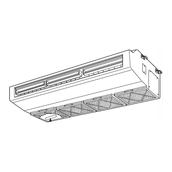
Page 7: Part Names And Functions
PART NAMES AND FUNCTIONS Indoor (Main) Unit Left/right guide vanes Change the direction of airflow Air outlet from the horizontal blower. Oil filter (Air intake) w It prevents oil from Up/down guide vanes getting into the unit. Change the direction of airflow from the Air intake vartical blower. - Page 8 Display “Sensor” indication Displayed when the remote controller sensor is used. Day-of-Week For purposes of this explanation, Shows the current day of the week. all parts of the display are shown as lit. During actual operation, only Time/Timer Display the relevant items will be lit. “Locked”...
-
Page 9: Specifications
SPECIFICATIONS Service Ref. PCA-RP71HA Mode Cooling Heating Power supply(phase, cycle, voltage) Single phase, 50Hz, 230V 0.09 Input 0.09 0.43 0.43 Running current 0.86 Starting current 0.86 External finish Stainless steel Heat exchanger Plate fin coil Fan(drive) x No. Sirocco fan (direct) x 2 Fan motor output 0.04 K/min(CFM) -
Page 10: Noise Criterion Curves
NOISE CRITERION CURVES PCA-RP125HA PCA-RP71HA NOTCH SPL(dB) LINE NOTCH SPL(dB) LINE High High NC-70 NC-70 NC-60 NC-60 NC-50 NC-50 NC-40 NC-40 NC-30 NC-30 APPROXIMATE APPROXIMATE TERESHOLD OF TERESHOLD OF HEARING FOR HEARING FOR NC-20 NC-20 CONTINUOUS CONTINUOUS NOISE NOISE 1000 2000 4000 8000... -
Page 11: Outlines And Dimensions
OUTLINES AND DIMENSIONS PCA-RP71HA Unit : mm... - Page 12 Unit : mm PCA-RP125HA...
-
Page 13: Wiring Diagram
WIRING DIAGRAM PCA-RP71HA PCA-RP125HA [ LEGEND ] SYMBOL NAME SYMBOL NAME P. B INDOOR POWER BOARD MF1, MF2 FAN MOTOR I. B INDOOR CONTROLLER BOARD C1, C2 CAPACITOR(FAN MOTOR) FUSE FUSE (T6.3AL250V) DEW PREVENTION HEATER VARISTOR TERMINAL BLOCK(INDOOR UNIT CN2L CONNECTOR (LOSSNAY) POWER (OPTION)) CN32... -
Page 14: Refrigerant System Diagram
REFRIGERANT SYSTEM DIAGRAM Unit : mm PCA-RP71HA PCA-RP125HA Strainer Heat exchanger Refrigerant GAS pipe connection (Flare) Condenser/evaporator temperature thermistor (TH5) Refrigerant flow in cooling Refrigerant flow in heating Refrigerant LIQUID pipe connection (Flare) Pipe temperature thermistor/liquid Room temperature (TH2) thermistor (TH1) Strainer Distributor with strainer... -
Page 15: Troubleshooting
TROUBLESHOOTING 9-1. TROUBLESHOOTING <Error code display by self-diagnosis and actions to be taken for service (summary)> Present and past error codes are logged and displayed on the wired remote controller or controller board of outdoor unit. Actions to be taken for service and the inferior phenomenon reoccurrence at field are summarized in the table below. Check the contents below before investigating details. - Page 16 Note: Refer to the manual of outdoor unit for the details of display 9-2. SELF-DIAGNOSIS ACTION TABLE such as F, U, and other E. Error Code Meaning of error code and detection method Countermeasure Cause Abnormality of room temperature 1 Defective thermistor 1~3 Check resistance value of thermistor.
- Page 17 Error Code Meaning of error code and detection method Countermeasure Cause Freezing/overheating protection is (Cooling or drying mode) (Cooling or drying mode) working 1 Clogged filter (reduced airflow) 1 Check clogs of the filter. 1 Freezing protection (Cooling mode) 2 Short cycle of air path 2 Remove shields.
- Page 18 Error Code Meaning of error code and detection method Countermeasure Cause 1 Defective thermistor Abnormality of pipe temperature ther- 1~3 Check resistance value of thermistor. mistor / Condenser-Evaporator (TH5) characteristics For characteristics, refer to (P1) above. 2 Check contact failure of connector (CN29) 1 The unit is in three-minute resume pro- 2 Contact failure of connector on the indoor controller board.
- Page 19 Error Code Meaning of error code and detection method Countermeasure Cause ∗ Check LED display on the outdoor control cir- Indoor/outdoor unit communication 1 Contact failure, short circuit or, error (Signal receiving error) cuit board. (Connect A-control service tool, mis-wiring (converse wiring) of 1 Abnormal if indoor controller board PAC-SK52ST.) indoor/outdoor unit connecting...
-
Page 20: Indoor Unit
9-3. TROUBLESHOOTING BY INFERIOR PHENOMENA Note: Refer to the manual of outdoor unit for the detail of remote controller. Phenomena Cause Countermeasure (1)LED2 on indoor controller board • When LED1 on indoor controller board is also off. 1 Power supply of rated voltage is not supplied to out- 1 Check the voltage of outdoor power is off. - Page 21 Note: Refer to the manual of outdoor unit for the detail of remote controller. Phenomena Cause Countermeasure (2)LED2 on indoor controller board • When LED1 on indoor controller board is also blinking. Check indoor/outdoor unit connecting wire Connection failure of indoor/outdoor unit connecting for connection failure.
- Page 22 9-5. HOW TO CHECK THE PARTS PCA-RP71HA PCA-RP125HA Parts name Check points Room temperature Disconnect the connector then measure the resistance using a tester. thermistor (TH1) (Surrounding temperature 10:~30:) Pipe temperature thermistor (TH2) Normal Abnormal (Refer to <Thermistor Characteristic graph> for a detail.) Condenser/Evaporator 4.3k"~9.6k"...
- Page 23 9-6. TEST POINT DIAGRAM 9-6-1. Power board PCA-RP71HA PCA-RP125HA CN2S Connect to the indoor controller board (CN2D) Between 1 1 to 3 3 12.6-13.7V DC (Pin1 1 (+)) CNSK Connect to the indoor controller board (CNDK) 1 1 to 3 3 220-240V AC Between...
- Page 24 9-6-2. Indoor controller board PCA-RP71HA PCA-RP125HA CN2D LED1 Connector to the indoor LED2 LED3 Power supply power board (CN2S) Power supply Transmission (I.B) (12.5~13.7V DC) (R.B) (Indoor/outdoor) CN3C – Transmission (Indoor/outdoor) CN22 (0~24V DC) Remote controller connecting wire Non polarity –...
- Page 25 9-7. FUNCTIONS OF DIP SWITCH AND JUMPER WIRE Each function is controlled by the dip switch and the jumper wire on control p.c. board. SW1 and SW2 are equipped only for service parts. Model setting and capacity setting are memorized in the nonvolatile memory of the control p.c. board of the unit.
-
Page 26: Disassembly Procedure
DISASSEMBLY PROCEDURE PCA-RP125HA OPERATING PROCEDURE PHOTOS&ILLUSTRATIONS 1. Removing the oil filter Figure 1 (1) Slide the oil filter towards you to remove. (See figure 1.) Oil filter 2. Removing the terminal block box cover Photo 1 Filter rail Fan guard (1) Remove the oil filter. - Page 27 OPERATING PROCEDURE PHOTOS&ILLUSTRATIONS 4. Removing the fan motor Photo 4 (1) Remove the oil filter. (See figure 1.) (2) Remove the control box cover. (See photo 2.) Filter reil (3) Remove the room temperature thermistor connector (CN20) on the indoor controller board. (See photo 3.) (4) Remove a filter rail that is the nearest to the control box.
- Page 28 OPERATING PROCEDURE PHOTOS 6. Removing the pipe temperature thermistor Photo 8 Relay connector (1) Remove the oil filter. (See figure 1.) (2) Remove the fan guard. (See photo 1.) (3) Remove the terminal block box cover. (4) Remove the white relay connector (2P) in the terminal block box.
- Page 29 OPERATING PROCEDURE PHOTOS 9. Removing the guide vane Photo 13 Guide vane (1) Remove the oil filter. (See figure 1.) (2) Remove the 3 filter rails. (See photo 1, 4.) (3) Remove the under panel. (See photo 11.) (4) Remove the drain pan. (See photo 12.) (5) Remove the 3 screws (4 10) for guide vane, and remove the guide vane.
-
Page 30: Parts List
PARTS LIST STRUCTURAL PART PCA-RP71HA PCA-RP125HA Q'ty / set Price Wiring Recom- Remarks Parts No. Parts Name Specifications PCA-RP Diagram mended (Drawing No.) Symbol Q'ty Unit Amount 71HA 125HA R01 13N 809 LEG-L R01 13N 662 SIDE PLATE-L T7W E02 676 REAR PANEL T7W E03 676 REAR PANEL... - Page 31 18,19 FAN PARTS PCA-RP71HA PCA-RP125HA Part numbers that are circled are not shown in the figure. Q'ty / set Price Wiring Recom- Remarks Parts No. Parts Name Specifications PCA-RP Diagram mended (Drawing No.) Symbol Q'ty Unit Amount 71HA 125HA R01 12N 110 T.
- Page 32 T7W E08 713 HEAD OFFICE : MITSUBISHI DENKI BLDG., 2-2-3, MARUNOUCHI, CHIYODA-KU, TOKYO 100-8310, JAPAN New publication, effective Jun. 2005. CCopyright 2005 MITSUBISHI ELECTRIC ENGINEERING CO., LTD. Specifications subject to change without notice. Distributed in Jun. 2005 No.OC329 PDF 9...
Need help?
Do you have a question about the PCA-RP71HA PCA-RP71HA and is the answer not in the manual?
Questions and answers