Advertisement
EC DECLARATION OF CONFORMITY
The manufacturer of the product covered by this Declaration is.
The manufacturer hereby declares that the machine as detailed in this declaration fulfils all the
relevant provisions of the Machinery Directive and other appropriate directives as detailed below.
The manufacture further declares that the machine as detailed in this declaration, where applicable,
fulfils the relevant provisions of the essential health and safety requirements.
The Directives covered by this Declaration are as detailed below
98/37/EEC The Machinery Directive.
2006/95/EC. Low Voltage Equipment Directive.
2004/108/EC. Electromagnetic Compatibility Directive,
93/68/EC. The CE Marking Directive.
2002/95/EC. The Restriction of the Use of certain Hazardous Substances in Electrical Equipment
(RoHS) Directive
2002/96/EC as amended by 2003/108/EC The Waste Electrical and Electronic Equipment (WEEE)
Directive.
And is in conformity with the applicable requirements of the following documents
??
Product Details:
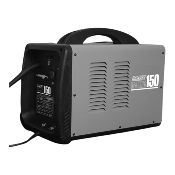
Description: Mig Welder
Model No: IM-MIG150
Brand Name: Impax
Name and address of technical documentation holder.
The technical documentation required to demonstrate that the product meets the requirements of
directive has been compiled and is available for inspection by the relevant enforcement authorities.
Signed:
Senior Quality Control Manager.
NAP Brands Ltd.
Napier House, Unit 7, Corunna Court, Warwick, United Kingdom CV34 5HQ
Date:.30.08.2013
After sales support: Tel: 0844 264 2485 Website: www.impaxpowertools.com
NAP Brands Ltd.
Napier House, Unit 7, Corunna Court,
Warwick, United Kingdom CV34 5HQ
Print: Mark Shannon
??
Advertisement
Table of Contents

Related Manuals for Impax IM-MIG150


Summary of Contents for Impax IM-MIG150
-
Page 1: Ec Declaration Of Conformity
And is in conformity with the applicable requirements of the following documents Product Details: Description: Mig Welder Model No: IM-MIG150 Brand Name: Impax Name and address of technical documentation holder. The technical documentation required to demonstrate that the product meets the requirements of directive has been compiled and is available for inspection by the relevant enforcement authorities. - Page 2 150A MIG WELDER IM-MIG150 Always Read Instruction Manual Retain for Future Reference...
-
Page 3: Certificate Of Guarantee
CERTIFICATE OF GUARANTEE This product is guaranteed for a period of 1 Year, with effect from the date of purchase and applies only to the original purchaser. This guarantee only applies to defects arising from, defective materials and or faulty workmanship that become evident during the guarantee period only and does not include consumable items. -
Page 4: Safety Information
SAFETY INFORMATION Before attempting to operate the machine, it is c) computer and other control equipment; essential that you read this manual thoroughly d) safety critical equipment, e.g. guarding of and carefully follow all instructions given. In industrial equipment; doing so you will ensure the safety of yourself and that of others around you, and you can also e) pacemakers and hearing aids etc.;... - Page 5 SAFETY INFORMATION Sweat, sea water, or moisture between body Electrode and an electrically LIVE part - or earthed metal - Equipment With Output On/Off Control reduces the body surface electrical resistance, (Contactor) enabling dangerous and possibly lethal currents Welding power sources for use with the gas to flow through the body.
- Page 6 SAFETY INFORMATION Safety Devices Recovery usually occurs within 1 to 2 days of Safety devices such as interlocks and circuit removal from exposure. breakers should not be disconnected or shunted To minimise the generation of toxic fumes, anti- out. Before installation, inspection, or service of corrosion plating, paint, other coatings and equipment, shut OFF all power and remove line surface contamination in the weld region should...
- Page 7 SAFETY INFORMATION The precise choice of the shade of glass filter in may also be needed. Welding produces these shields depends on the type of welding quantities of molten droplets of metal which are operation, since they vary in their light output. scattered in all directions.
- Page 8 SAFETY INFORMATION d) combustibles adjacent to walls, ceilings, roofs screw should be released by turning it anti- or metal partitions can be ignited by radiant clockwise. The cylinder valve should then be or conducted heat. opened slowly to prevent a surge of high pressure gas into the regulator.
- Page 9 SAFETY INFORMATION MIG/MAG (Metal Inert Gas / Metal Active Gas) IP 23 protection against limited spraying welding produces fumes, sparks and fused IP 24 protection against spraying from all metal projectiles. directions Remove all flammable substances and materials If there is a risk of heavy rain, a cover for the from the work area.
- Page 10 SAFETY INFORMATION Both wire and shielding gas composition are Aluminium Alloys essential variables in MIG/MAG welding and will, The main concerns when welding aluminium therefore, influence the process performance. alloys are the risk of solidification cracking and porosity. Wires for Note: Tubular / Flux Cored wire produces its own shielding gas and does not require the use AWS A5.10/A5.10M: Specification for bare...
- Page 11 SAFETY INFORMATION The following types of welding operation c) Keep children and bystanders away while must be performed by a qualified coded operating a power tool. Distractions can welder and approved by a qualified welding cause you to lose control. inspector.
-
Page 12: Electrical Information
SAFETY INFORMATION c) Avoid accidental starting. Ensure the c) Disconnect the plug from the power switch is in the off position before source before making any adjustments, plugging in. Carrying power tools with your changing accessories, or storing power finger on the switch or plugging in power tools. - Page 13 COMPONENTS Component List 1. ON/OFF switch 12. Face mask 2. Thermal cut out indicator 13. Flux cored wire 3. Carry handle 14. Shroud 4. Welding current control switch (Min/Max) 15. Contact tip 5. Welding current control switch (1/2) 16. Earth clamp 6.
-
Page 14: Unpacking And Assembly
UNPACKING AND ASSEMBLY Unpacking Insert the clear glass panel first, followed by the Caution! This packaging contains sharp objects. dark glass panel into the recess in the shield, Take care when unpacking. Remove the i.e. the clear glass MUST be on the outside of machine, together with the accessories the shield. - Page 15 ASSEMBLY Remove the plastic wrapper then slide the spool Fig 6 back over the hub, ensuring that it sits snugly, and replace the collar, spring and plastic knob, tightening it sufficiently to allow the spool to rotate smoothly but with a slight amount of braking friction.
- Page 16 Gas: Disposable gas bottles are available from your Impax dealer, or rechargeable bottles from 11.2 your welding supply shop. Always use the appropriate gas for the material...
-
Page 17: Operation
OPERATION Operation gas (when required) for the material to be Warning! If you have no welding experience, welded. When welding outside it may be we recommend you seek training from an necessary to create a windbreak as a break experienced person. down in the gas shield can result in a poor weld. - Page 18 OPERATION welding current is changed. Fig 14 60º Listen to the sound made. An irregular crackling sound denotes too high a wire speed. Decrease >30mm the speed until a regular, strong buzzing sound is heard. IMPORTANT – Thermostatic Protection 2-3mm (Duty Cycle) This product has a rated duty cycle of 60%.
-
Page 19: Maintenance
NEVER use any dark filter lens other than that provided by Impax, or one with the same certified ‘Optical class’ (degree of protection). The shield should always be cleaned with a clean soft cloth after use, ensuring the lenses are clean. -
Page 20: Troubleshooting
TROUBLESHOOTING PROBLEM POSSIBLE CAUSE REMEDY No weld current Blown rectifier. Replace rectifier. (plug fuse blowing). No weld current Poor earth clamp connection. Check and clean up connections. Break in earth lead. Replace earth lead. Break in torch lead. Replace torch or lead. Feed motor not working. - Page 21 ENVIRONMENTAL PROTECTION & SYMBOLS Information for (private householders) for the environmentally responsible disposal of Waste Electrical and Electronic Equipment (WEEE) This symbol on products and or accompanying documents indicates that used and end of life electrical and electronic equipment should not be disposed of in household waste.
- Page 22 SYMBOLS Symbols and Technical Data EN 60974-1: European standard relating to Welding Power Supply’s for limited use 1998+A1+A2 IM-MIG150 Type ID Single phase transformer Metal inert & active gas welding including the use of flux cored wire 50Hz Nominal mains frequency...
Need help?
Do you have a question about the IM-MIG150 and is the answer not in the manual?
Questions and answers