Table of Contents
Advertisement
Quick Links
DECLARATION OF CONFORMITY
1.
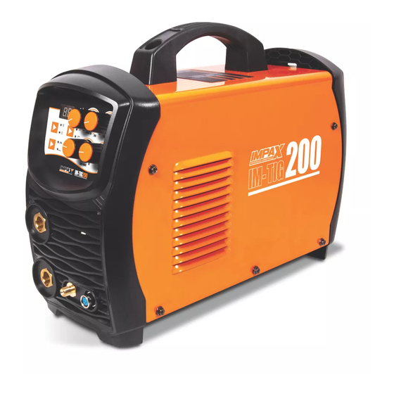
Product model: IM-TIG200
2.
Name and address of the manufacturer or his authorised representative:
3.
This declaration of conformity is issued under the sole responsibility of the manufacturer.
4.
Object of the declaration:
Equipment: 200A TIG PULSE/MMA Welder
Brand name: IMPAX
Model/type: IM-TIG200
5.
The object of the declaration described above is in conformity with the relevant statutory requirements:
Supply of Machinery (Safety) Regulations 2008
Electrical Equipment (Safety) Regulations 2016
Electromagnetic Compatibility Regulations 2016
The Restriction of the Use of Certain Hazardous Substances in Electrical and Electronic Equipment
Regulations 2012
6.
References to the relevant designated standards used or references to the other technical
specifications in relation to which conformity is declared:
EN IEC 60974-1
EN IEC 60974-10
BS EN IEC 60974-1
BS EN IEC 60974-10
7.
The person authorized to compile the technical file:
Name: Robert Redfern
Address: Nap Brands Ltd. Office 20, Fleming Court Business Centre, Leigh Road, Eastleigh,
Hampshire SO50 9YN
Signed for and on behalf of:
Authorised Representative
Robert Redfern, Technical Manager
03/03/2022
After sales support: Tel: 0344 264 2485 Website: www.impaxpowertools.com
NAP BRANDS LTD. Office 20, Fleming Court Business Centre,
Leigh Road, Eastleigh, Hampshire SO50 9YN
Tel: +44 (0)23 8064 9650. Email: sales@napbrands.co.uk
22
Advertisement
Table of Contents
Troubleshooting

Subscribe to Our Youtube Channel
Related Manuals for Impax IM-TIG200


Summary of Contents for Impax IM-TIG200
- Page 1 DECLARATION OF CONFORMITY Product model: IM-TIG200 Name and address of the manufacturer or his authorised representative: NAP BRANDS LTD. Office 20, Fleming Court Business Centre, Leigh Road, Eastleigh, Hampshire SO50 9YN Tel: +44 (0)23 8064 9650. Email: sales@napbrands.co.uk This declaration of conformity is issued under the sole responsibility of the manufacturer.
- Page 2 200A TIG PULSE/MMA WELDER IM-TIG200 Always Read Instruction Manual Retain for Future Reference...
-
Page 3: Certificate Of Guarantee
CERTIFICATE OF GUARANTEE This product is guaranteed for a period of 1 Year, with effect from the date of purchase and applies only to the original purchaser. This guarantee only applies to defects arising from, defective materials and or faulty workmanship that become evident during the guarantee period only and does not include consumable items. -
Page 4: Safety Information
SAFETY INFORMATION Your safety and the safety of others are very important. We have provided many important safety messages in this manual and on your appliance. Always read and obey all safety messages. This is the safety alert symbol. This symbol alerts you to potential hazards that can kill or hurt you and others. All safety messages will follow the safety alert symbol and either the word “DANGER”... - Page 5 SAFETY INFORMATION General Welding Safety installed or improperly grounded equipment is a hazard. The Workshop Environment Housekeeping is extremely important to avoid 1. Do not touch live electrical parts. injury from slips, trips and falls, damage to 2. Wear dry, hole-free insulating gloves and equipment and fire.
- Page 6 SAFETY INFORMATION Shock Prevention Electrode Holders Exposed live conductors or other bare metal in Fully insulated electrode holders should be the welding circuit, or in unearthed, electrically- used. Do NOT use holders with protruding LIVE equipment can fatally shock a person screws or with any form of damage.
- Page 7 SAFETY INFORMATION Changing Electrodes produced in the arc, such as ozone or oxides of The electrode holder should be isolated when nitrogen, and decomposition products from any changing the electrode, where a work piece is paint or coating which was on the metal earthed.
- Page 8 SAFETY INFORMATION 5. Work in a confined space only if it is well Avoid paint spray rooms, dip tanks, storage ventilated, or while wearing an air-supplied areas, ventilators. If the work cannot be moved, respirator. move combustibles at least 10M, away out of reach of sparks and heat;...
- Page 9 SAFETY INFORMATION Cylinders Can Explode If Damaged through small cracks and openings to Shielding gas cylinders contain gas under adjacent areas. high pressure. If damaged, a cylinder can 5. Watch for fire, and keep a fire extinguisher explode. Since gas cylinders are normally nearby.
- Page 10 SAFETY INFORMATION Sparks Can Cause Battery Gases To Explode Falling Unit Can Cause Injury SPARKS can cause BATTERY 1. Lift unit with handle on top of GASES TO EXPLODE; BATTERY case. ACID can burn eyes and skin. 2. Use handcart or similar device of Batteries contain acid and adequate capacity.
- Page 11 SAFETY INFORMATION...
- Page 12 SAFETY INFORMATION H.F. Radiation Can Cause Interference Do not place your body between the 1. High-frequency (H.F.) can electrode and work cables. If the electrode interfere with radio navigation, cable is on your right side, the work cable safety services, computers, should also be on your right side.
- Page 13 SAFETY INFORMATION Specific Safety Instructions Do not weld on containers or pipes that hold or Use the welding power supply as indicated in have held flammable liquid or gases (danger of the instruction manual. Improper use of this explosion) or on materials cleaned with welding power supply can be dangerous for chlorinated solvents or on varnished surfaces persons, animals or objects.
- Page 14 If you have a problem with the machine Power disconnect switch must be available contact your local IMPAX dealer. near the welding power source. 10. NEVER use or store in a wet/damp 25. Fully insulated electrode holders should be environment.
- Page 15 SAFETY INFORMATION The following types of welding operation c) Keep children and bystanders away while must be performed by a qualified coded operating a power tool. Distractions can welder and approved by a qualified welding cause you to lose control. inspector.
- Page 16 SAFETY INFORMATION c) Avoid accidental starting. Ensure the Power tools are dangerous in the hands of switch is in the off position before untrained users. plugging in. Carrying power tools with your e) Maintain power tools. Check for finger on the switch or plugging in power misalignment or binding of moving parts, tools that have the switch on invites breakage of parts and any other condition...
-
Page 17: Installation
INSTALLATION Environment Read the section on electromagnetic These units are designed for use in compatibility in this manual. environments with increased hazard of electric • Do not operate in areas with an ambient shock. temperature greater than 40°C. A. Examples of environments with increased Tilting hazard of electric shock are: Place the machine directly on a secure, level... - Page 18 Do not touch members radiating antennas. electrically live parts 6. Keep all panels securely in place. The IM-TIG200 Welder requires a 230V 50Hz All electrical conductors within 50 ft (15.2m) supply. of the welder should be enclosed in Connect wires according to national coding.
-
Page 19: Electrical Information
ELECTRICAL INFORMATION WARNING! THIS APPLIANCE MUST BE Models Fitted Without Plug EARTHED 230V Supply Models Fitted With 13A Plug Connect the mains lead to a suitably fused 230 Welders fitted with a standard 13 amp BS 1363 Volt (50Hz) electrical supply. The fuse rating plug, should be connected to a to a 230 volt should correspond to that shown on the (50Hz) domestic electrical supply and we... - Page 20 COMPONENTS Component List 15. Carry handle 1. Digital display 16. On/Off switch 2. TIG/MMA selector button 17. Power cable 3. Amps control dial 18. Face mask 4. Pulse control dial 19. TIG torch 5. Down slope dial 21. Earth clamp 6.
- Page 21 UNPACKING Caution! This packaging contains sharp objects. be returned together in their original packaging Take care when unpacking. Remove the to the retailer. machine, together with the accessories Do not throw the packaging away, keep it safe supplied, from the packaging. Check carefully to throughout the guarantee period, then recycle if ensure that the machine is in good condition possible, otherwise dispose of it by the proper...
- Page 22 MMA ASSEMBLY & OPERATION Assembly Operation Note: Before carrying out any assembly or WARNING! If you have no welding experience, disassembly of the unit please ensure that the we recommend you seek training from an unit is not connected to the electrical supply. experienced person.
-
Page 23: Mma Operation
MMA OPERATION The chart below is an indicator of the electrode Set the amperage (see Table 1) by adjusting the diameter and the corresponding welding amps control dial (Fig.7) until the desired setting current. This is intended as a guide only as is reached. - Page 24 MMA OPERATION Wear a leather apron and gauntlets. This will Do not hit the electrode on the workpiece as protect you from being burnt or sparks setting this may damage the electrode. Withdraw with a alight to your clothes. clean movement at the end of the welding run. Place the work so that the direction of welding Note: This is the most difficult aspect for most is across, rather than to or from, your body.
- Page 25 MMA OPERATION Rate of Travel When welding together material over 30mm in After the arc is struck, your next concern is to thickness prepare the material as shown in maintain it, and this requires moving the Fig.12 filling up the space with several layers of electrode tip towards the molten pool at the weld, welding each side in turn with each same rate as it is melting away.
- Page 26 MMA OPERATION Cellulosic electrodes contain a high proportion Features: of cellulose in the coating and are characterised • Low hydrogen weld metal by a deeply penetrating arc and a rapid burn-off rate giving high welding speeds. Weld deposit • Requires high welding currents/speeds can be coarse and with fluid slag, deslagging •...
- Page 27 MMA OPERATION & MAINTENANCE Under these conditions and in original Do not touch electrically hot parts. packaging, electrode storage time is practically WARNING. Do not open this machine and do unlimited. It should be noted that electrodes are not introduce anything into its openings. Power now available in hermetically sealed packs supply must be disconnected from the machine which obviate the need for drying.
-
Page 28: Mma Welding Troubleshooting
MMA WELDING TROUBLESHOOTING Problem Possible Cause Remedy Control knob is set at a value Reduce the control knob until welding Welding current varying. that causes the welding current current is reasonably constant while to vary excessively with the arc prohibiting the electrode from sticking length. - Page 29 MMA WELDING TROUBLESHOOTING Problem Possible Cause Remedy Small electrodes used on heavy Use larger electrodes and preheat the Portions of the weld cold plate. plate. run do not fuse to the surface of the metal or edge of the joint. Welding current is too low.
- Page 30 TIG ASSEMBLY TIG Welding Connect the TIG torch control switch into the Insert the cable plug with the earth clamp into torch control outlet plug on the machine front the “+” socket on the front panel of the welding panel. machine, and tighten it clockwise.
- Page 31 Know Your Torch Fig 16 This TIG torch is designed to operate with the Grinding Preparation IM-TIG200 welder for welding on steels or Use a 60 Grit or finer aluminum oxide wheel stainless steels. This torch is ideal for light fabrication,welding repair and maintenance operations.
- Page 32 TIG GUN ASSEMBLY Tig Torch Components Back cap Collet Ceramic cup Tungsten Torch body Electrode Insulator or Heatshield Collet body Assembling The Tig Torch Fig 18 Ensure the Tig Torch is disconnected from the welder before commencing assembly. First make sure the insulator is seated properly then screw the collet body into the torch body (Fig.17), a very gentle nip with pliers will make sure of a good electrical connection between...
-
Page 33: Tig Operation
TIG OPERATION Operation Set the current by adjusting the amps control Before starting any welding activity ensure dial (Fig.22) until the desired setting is reached. that you have suitable eye protection and Adjustment 10-200A. protective clothing. Also take the necessary Fig 7 steps to protect any persons within the area. - Page 34 TIG OPERATION Release the TIG torch switch to end sequence. Fig 27 The machine will now decrease output to finish current in time set by down slope, Fig.25. Fig 25 When the trigger mode is in the 4 step position the following sequence will occur (Fig.28).
- Page 35 TIG OPERATION Connect the TIG torch leads as detailed on page Pulse TIG Mode arc. When the arc is established the HF stops, 29. Ensure that a suitable inert gas supply is and current rises to the preset value; Release the torch trigger, current decreases to the connected and the flow rate is set.
- Page 36 TIG OPERATION Remote Control Operation Tungsten Electrode Current Ranges If using a remote control current device connect it to the socket on the front of the machine. Electrode diameter (mm) DC Current (A) If you are using a foot pedal you must press the 1.0mm 30-60 Panel/Remote selector button to REMOTE mode...
- Page 37 TIG OPERATION Welding Polarity Filler material: The filler rods must deposit welds with mechanical characteristics appropriate for DC Electrode Negative Polarity (Direct the application. Current Straight Polarity) While Welding, there is a continuous flow of Copper TIG Welding electrons from the electrode to the workpiece. Since the TIG welding is a process characterized by high heat concentration, it is particularly This is the most used polarity, ensuring limited...
- Page 38 TIG OPERATION Tungsten Electrode Types Electrode Type Welding Application Features Colour Code (Ground Finish) Thoriated 2%. DC welding of mild Excellent arc starting, steel, stainless steel Long life, High current and copper. carrying capacity. Zirconated 1% High quality AC Self cleaning, Long White welding of aluminium, life, Maintains balled...
-
Page 39: Tig Troubleshooting
TIG TROUBLESHOOTING Problem Possible Cause Remedy Welding current is too low. Increase weld current and/or faulty joint Excessive bead build up or poor penetration preparation. or poor fusion at edges of weld. Welding current is too high. Decrease weld current. Weld bead too wide and flat or undercut at edges of weld or... - Page 40 TIG TROUBLESHOOTING Problem Possible Cause Remedy Electrode contaminated by Clean the electrode by grinding off the Dirty weld pool. contact with work piece or filler contaminates. rod material. Work piece surface has foreign Clean surface. material on it. Gas contaminated with air. Check gas lines for cuts and loose fitting or change gas cylinder.
-
Page 41: Maintenance
After each repair, perform proper tests to ensure safety. NEVER use any dark filter lens other than that provided by IMPAX, or one with the same certified ‘Optical class’ (degree of protection). CAUTION The shield should always be cleaned with a... -
Page 42: Troubleshooting
TROUBLESHOOTING Follow all safety precautions whenever diagnosing or servicing the DANGER tool. Disconnect power supply before service. Problem Possible Cause Remedy The primary supply voltage has Switch ON the primary supply voltage. The welding arc cannot be not been switched ON. established. -
Page 43: Environmental Protection
TROUBLESHOOTING Problem Possible Cause Remedy Bad weld connections. Clean and tighten weld connections. Erratic or improper arc or welding output. Polarity incorrect. Connect polarity correctly. Workpiece painted or dirty. Clean workpiece thoroughly. Nozzle obstructed by welding Clean or replace nozzle. spatter. - Page 44 SYMBOLS Symbols and Technical Data EN 60974-6:2003 European standard relating to Welding Power Supply’s for limited use IM-TIG200 Type ID Single phase transformer Symbol for manual arc welding and covered electrodes 50Hz Nominal mains frequency Ø Diameter of electrodes No load voltage …A/…V to …A/…V Range of output...
- Page 45 SYMBOLS The rating plate on this product may show symbols. These represent important information about the product or instructions on its use. Conforms to European safety Waste electrical products standards. should not be disposed of with household waste. Please recycle where facilities exist. Check with your Local Conforms to UK safety Authority or retailer for...
-
Page 46: Wiring Diagram
WIRING DIAGRAM... - Page 47 NOTES...
-
Page 48: Ec Declaration Of Conformity
EC DECLARATION OF CONFORMITY Product model: IM-TIG200 Name and address of the manufacturer or his authorised representative: Nuair Ibérica, Lda. Rua da Zona Industrial, 560, 4520-114, Santa Maria da Feira, Portugal Tel: +351 256 580 930. Email: sat@nuair.pt This declaration of conformity is issued under the sole responsibility of the manufacturer.
Need help?
Do you have a question about the IM-TIG200 and is the answer not in the manual?
Questions and answers