Table of Contents
Advertisement
Quick Links
Advertisement
Table of Contents

Related Manuals for Innovaphone IP 400


Summary of Contents for Innovaphone IP 400
- Page 1 VoIP Gateways IP 400 administrator manual P u r e I P - T e l e p h o n y...
- Page 2 Release 5.01, 2nd edition, April 2005 PDF version available for download at: http://www.innovaphone.com ® Copyright © 2001-2005 innovaphone Böblinger Str. 76 71065 Sindelfingen, Germany Tel +49 (70 31) 7 30 09-0 Fax +49 (70 31) 7 30 09-99 http://www.innovaphone.com...
- Page 3 VoIP Gateways IP 400 Version 5.01 Manual...
- Page 4 This documentation is there- fore supplied under exclusion of any liability or warranty of suitability for specific purposes. innovaphone reserves the right to improve or modify this documenta- tion without prior notice.
-
Page 5: Table Of Contents
Table of contents 1 About this manual ................6 Notes, tips and cautions............6 2 Introduction, commissioning and installation of the VoIP gateway7 Connections and user controls IP 400 ........7 2.1.1 Connections on the rear side ..........7 2.1.2 Indicators on the front ............. - Page 6 Allowing dial-up access to the entire network ....39 4.2.9 The ENUM protocol ............40 4.2.10 To set up the ENUM protocol on an innovaphone gateway 41 4.2.11 Rerouting outgoing calls ..........45 5 Configuration of the ISDN interfaces..........46 IP 400 ISDN interfaces ............
- Page 7 Defining the VoIP Tracing Level ........81 Management of VoIP devices via RAS (Gatekeeper) ... 81 6.2.1 Special features, when configuring innovaphone devices .. 83 Static management of VoIP devices ........84 Registering the gateway with another gatekeeper ..... 85 Routing via the ENUM protocol ..........
- Page 8 Configuration of the PBX components in the gateway ..109 8 Definition of various operating parameters........ 110 General settings ..............110 8.1.1 Defining the gateway name .......... 110 8.1.2 Defining the user administrator and -password....110 8.1.3 Defining the source for time and date......110 8.1.4 Defining the port for the local HTTP server ....
- Page 9 9.4.1 Home submenu ............137 Appendix A: Safety instructions ............138 Safety instructions for the IP 400 ..........138 Appendix B: Troubleshooting ............140 Typical problems ................. 140 NAT and firewalls ................ 143 Appendix C: ISDN error codes............148 Appendix D: The innovaphone DHCP Client ........
-
Page 10: About This Manual
The manufacturer assumes no responsibility for any personal injury, damage to property or subsequent damage that can be attributed to improper use of the device. Some screenshots stem from other innovaphone products. But they are of the contents the same as the IP 400 ones. Caution Observe the safety instructions specified in the respective manuals at all times. -
Page 11: Introduction, Commissioning And Installation Of The Voip Gateway7
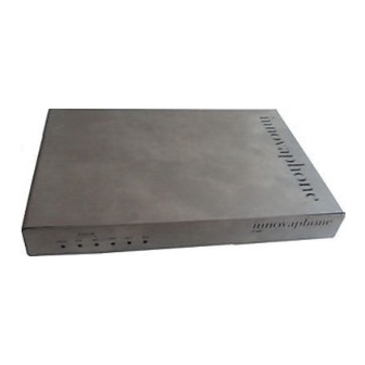
Introduction, commissioning and installation of the VoIP gateway Connections and user controls IP 400 2.1.1 Connections on the rear side Fig. 1 The IP 400 connections The following connectors/switches can be found on the back of the gateway (from left to right):... -
Page 12: Indicators On The Front
Function Ethernet RJ 45-socket. To connect to 10 Mbit/s Ethernet connect to Switch to the left, when connecting the IP 400 Ethernet interface to a hub. connect to PC Switch to the right, when connecting the IP 400 Ethernet interface directly to a PC. -
Page 13: The Ip 400 Serial Number Label
Fig. 3 The serial number label The last three hexadecimal numbers ('XX-XX-XX' in the illustration) separated by a hyphen ('-') represent the serial number of your IP 400, while the first three hexadecimal numbers are innovaphone‘s, fixed, manufacturer's identification code. -
Page 14: Commissioning And Installation Of The Ip 400
Note the section “Safety instructions for the IP 400” from page 138. The IP 400 is suitable for wall mounting. The horizontal distance between the sus- pension points is 12 cm. Take care not to damage the protective film of the PCB when mounting the IP 400. -
Page 15: Configuration Of Access To The Local Network
DHCP. In this case your PC also needs to be provided with a twisted-pair Ethernet adapter (10 Base-T for the IP 400). Refer to section 2.2.3 “Setting the IP-interface parameters via DHCP” from page 13, if a DHCP server is available. -
Page 16: Switching On The Gateway
2.2.2 Switching on the gateway Caution Connect the gateway to the nearest wall socket using the supplied external power supply (IP 400, 100-240 V). Only use the external power supply. Other power supplies could damage the gateway. The mains socket must be close to the device and easily accessible. The only way of interrupting the power supply to the device is by removing the mains lead of the device, or of the external power supply, from the mains socket. -
Page 17: Setting The Ip-Interface Parameters Via Dhcp
2.2.3 Setting the IP-interface parameters via DHCP ... for experts • There are basically two ways of configuring an IP address for your gate- way. • When delivered from the factory, DHCP is in an automatic mode. You can force the DHCP into automatic mode with a long reset (at least 3 seconds). •... - Page 18 Now, proceed as follows: • Set the Ethernet switch on the back to the “connect to Hub” position. • Connect Ethernet RJ 45-connector gateway RJ 45-connector of your Ethernet hub or switch using a twisted pair cable. • Switch the gateway off and then on again, to activate the DHCP client. The gateway will now be now assigned an IP address.
- Page 19 Under Linux, you can use the “nmblookup” command for this purpose, provided the “SAMBA” package has been installed: [dvl@cobalt ~ 2] $. nmblookup ip400-XX-XX-XX Got a positive name query response from 195.226.104.220 ( 195.226.104.220 ) 195.226.104.220 ip400-XX-XX-XX<00> [dvl@cobalt ~ 3] $. The installation can be concluded, using your Web Browser or, using com- mand lines with the help of Telnet.
-
Page 20: Setting The Ip-Interface Parameters Without Dhcp
2.2.4 Setting the IP-interface parameters without DHCP You will have to set the IP interface parameters of the gateway yourself, if your network does not have a DHCP server..for experts • If possible, configure your PC using DHCP! •... - Page 21 If the computer is connected to the network by a twisted pair cable with RJ45- plugs, disconnect the cable from Hub or Switch or remove it from the wall socket, depending on where your computer is connected up. • Set the Ethernet Switch on the back to “connect to PC”. This makes the gateway operate like an Ethernet Hub for your computer.
- Page 22 With Windows, this is done by adjusting the settings for the TCP/IP- protocol accordingly in the Network area in System control. In this case, the com- puter must be restarted. The installation can be concluded, using your Web Browser. In this manual, we describe the procedure using the Web Browser, which is usually the most convenient one, for common application scenarios.
- Page 23 If you want to configure further gateways in the same way, you have to delete the assignment of the IP address to the hardware address first before connecting the next device to your PC. This is necessary, as the new device has to respond to the same IP address, despite having a different hardware address.
-
Page 24: General Information On Configuration
Here, you specify the parameters for your Internet or intranet access, if you also intend to use the gateway as an ISDN or a VPN router. The innovaphone VoIP gateway IP 400 can also be used as ISDN router and as VPN router (PPPoE). -
Page 25: General Information On The Configuration User Interface
Here you specify which terminal equipment is to be reached, under which number. The configuration of the optional innovaphone PBX components is described in a separate manual, supplied together with your innovaphone PBX licence. First, launch your Web Browser and enter the URL http://address/, where address is the IP address of the gateway to be con- figured. -
Page 26: Checking And Saving The Configuration
the left-hand window. You can choose names of your own for most of the configuration elements, by entering them in the Description field. These then appear in the tree dis- play on the left-hand side. Make frequent use of this option, as it will help you maintain an overview later on. - Page 27 dentally interrupted. If you decline the restart (Later button), you can enforce it later on, by clicking on the Reset or Reset when idle button. Reset is used for an immediate restart, whereas Reset when idle only restarts if there are no active calls. This prevents existing calls from being disconnected by a restart.
-
Page 28: Configuration Of The Ip Interfaces
Configuration of the IP interfaces Configuration of the Ethernet interface The Ethernet IP interface is usually configured when the gateway is commissioned and does normally not need to be changed again. If this does need changing, you can adjust the settings in the IP Interfaces > Ethernet Interface configura- tion applet. - Page 29 • The Full duplex checkbox is usually not activated. This option is only necessary with the IP 400. The IP 3000, IP 3000DD, IP 800, IP 202 and the IP 21 negotiate the full duplex mode auto- matically with the switch or hub.
-
Page 30: Dhcp Configuration Options
4.1.1 DHCP configuration options Besides the IP address actually assigned, your gateway's DHCP client processes the DHCP options specified in Table 5, provided that they were supplied when the DHCP lease was granted. Options supplied via DHCP always overwrite any parameters defined in the gate- way configuration. -
Page 31: Full Duplex Ethernet
Set your Ethernet switch to always run in full duplex mode, for the port to which the IP 400 is connected. This is necessary, as the operating mode of the IP 400 is not negotiated. Faults will occur if the IP 400 settings do not correspond to those of the Ethernet switch. -
Page 32: Configuration Of The Wan Interfaces
Any ISDN or PPPoE router with PPP capability can serve as a PPP remote entity. Fig. 5 on page 28 illustrates accessing a remote IP network using an IP 400 as an ISDN router. Fig. 6 on page 29 illustrates accessing the Internet via a DSL con- nection. - Page 33 local IP network Ethernet interface DSL modem DSL modem DSL line Internet Fig. 6 Connection to a DSL line using PPPoE The connection can also be established directly between two gateways, for exam- ple as part of a PBX link-up between two locations via a permanent ISDN connec- tion (leased line).
-
Page 34: General Considerations On The Configuration Of The Ppp Connections
One specific application of the ISDN WAN interface is to dial-in to the gateway for maintenance purposes. This enables remote maintenance of the gateway, without necessarily having access to the local IP network, as illustrated by Fig. 8 on page 30. IP access only to the gateway ! - Page 35 Compatibility problems may arise in practice, if the distant PPP entity used is not an innovaphone gateway. Try the option Adjust for Cisco’s PPP implementa- tion if a Cisco router is used at the remote location and problems arise in the transmission of voice data.
-
Page 36: Settings For Outgoing Isdn Ppp Dial-Up Connections
Configuration of the IP routes You can add separate IP routes for each PPP interface using the Add IP route button. The routes are configured in the same way as those for the Ethernet inter- face (see section 4.1 “Configuration of the Ethernet interface” from page 24). All IP routes must be defined explicitly. -
Page 37: Settings For Incoming Isdn Ppp Dial-Up Connections
tion at your gateway. • Enter the call number of the remote PPP entity to be called in the Dial remote number field. • Enter the appropriate data in the User and Password fields in the Out- going calls area, if your gateway is to provide authentication at the called distant PPP terminal. - Page 38 If this field remains empty, all data calls will be accepted at the selected ISDN interfaces. In this case however, it is not possible to assign these calls to the various PPP interfaces. Such configurations should thus be avoided. • Check the Allow incoming calls box.
-
Page 39: Settings For Incoming And Outgoing Isdn Ppp Dial-Up Connections
Expansion to Multilink You can accept a multilink connection via two bundled channels instead of a con- nection via a single B channel. • Check the Multilink box. • Leave the Dial remote number and Local subscriber number fields empty in the Numbers for 2nd Multilink channel area. Your gateway will accept calls for both channels on the same number, configured in the Sub- scriber number field. -
Page 40: Settings For Vpn Connections With Pptp
The innovaphone VoIP gateways can dial up to a remote server as PPTP client as well as providing a dial-up access point themselves. PPTP is ideal to link up two innovaphone VoIP gateways via the Internet. - Page 41 work with unofficial IP addresses which are known to both parties. To deactivate NAT, set the option Exclude from NAT. NAT is only required if a tunnel is set up to a network requiring official IP addresses. Dial-up of the VoIP gateway (client) to a PPTP server •...
-
Page 42: The Remote Maintenance Facility In The Standard Configuration
4.2.7 The remote maintenance facility in the standard configuration In the standard configuration, the PPP ISDN interface is configured to dial-up up for remote maintenance. This allows the gateway to be configured remotely from any PC with an ISDN card and a PPP remote data transmission programme (e.g. Windows DUN). -
Page 43: Allowing Dial-Up Access To The Entire Network
This configuration means that by plugging in an ISDN BRI point-to-multipoint exchange connection (e.g. a BRI connection to the exchange or a BRI line from a PBX) to the PPP interface, the gateway can be configured from any PC with a PPP dial up application. -
Page 44: The Enum Protocol
4.2.9 The ENUM protocol ENUM stands for a protocol, which has to do with mapping so-called E.164 num- bers to Uniform Resource Identifiers (URI). It defines rules to uniquely map a tel- ephone number to a domain. This domain can then be used, for example, to iden- tify addresses for IP telephony. -
Page 45: To Set Up The Enum Protocol On An Innovaphone Gateway
To be able to use the ENUM protocol, 3 VoIP interfaces have to be set up. To transmit the ENUM calls via the innovaphone PBX, to receive incoming ENUM calls and to forward these incoming calls to the innovaphone PBX. - Page 46 In the next step we will configure an interface for incoming calls, if this hasn't already been done. The interface must permit the acceptance of calls from any IP address, without previous registration: • In the configuration applet, select the path Config > VoIP Interfaces >...
- Page 47 So, in the next step we will configure the map to the Tone Interface, so that when you dial a 0, you can hear a dial-tone. • Click on the button Add map, whilst the cursor is in the previously config- ured route to ENUM.
- Page 48 ENUM ® protocol. If someone calls reception at innovaphone AG by dialling the telephone number +49 7031 73009-0, the associated number, sent to the ENUM interface will be 497031730090. It is irrelevant, where in the world this number was dialled.
-
Page 49: Rerouting Outgoing Calls
4.2.11 Rerouting outgoing calls Rerouting is supported. If the call to an ENUM interface should fail to be estab- lished, rerouting means looking for another, subsequent route and trying again. If rerouting is to work correctly, the Final map option must have been acti- vated for the three routes just set - international, national and local prefix. -
Page 50: Configuration Of The Isdn Interfaces
Configuration of the ISDN interfaces The IP 400 has two “virtual” interfaces, whose configuration is described in sec- tion 5.3 “Considerations on the configuration of the virtual interfaces” from page 66. The IP 400 has ISDN interfaces. To configure the ISDN interfaces you first need to decide about the following points: •... -
Page 51: Ip 400 Isdn Interfaces
Called numbers can be replaced via ADD CDPN MAP. These replacements only apply to this interface (separately for incoming/outgoing calls). IP 400 ISDN interfaces The IP 400 has three ISDN BRI interfaces, which are referred to as PPP, tel1 and tel2 (see page 7). •... -
Page 52: Considerations On The Configuration Of The Isdn Interfaces48
Technically, up to eight terminals can be connected to an ISDN interface. Note however, that from all these devices, only two calls can be made simultane- ously. Furthermore, it must be ensured that the total power consumption of all terminals does not exceed the permitted value of 4 Watts. •... -
Page 53: Volume Adjustment
Volume adjustment In some cases, it is desirable to adjust the basic volume level of an interface. The volume of the ISDN interfaces can be set, in the configuration applet, under Con- fig > ISDN, tone and HTTP Interfaces > TEL or PRI under Interface con- figuration in the Volume field, in the range from -31 to +32. -
Page 54: Suppression Of Specific Protocol Elements
Single digit dialling on terminals on point-to-multipoint connec- tions Normally, single digit dialling (overlapped sending) is not used to call terminals (i.e. devices in TE mode) on point-to-multipoint connections. Under certain cir- cumstances however, it is possible for gateways to be connected to a PBX system in precisely this mode and then also support incoming single digit dialling (over- lapped receive). -
Page 55: Usage At A Public Exchange Line (Dial-Up Or Permanent Connection)
For incoming calls at the ISDN interface, this is usually only done in the direction of the calling party if the interface is in NT mode, not however if it is in TE mode. In a few cases though, in particular when linking up PBXs via tie lines, it can be useful to also generate these tones in TE mode. - Page 56 • Use as an IP router for operation on a permanent connection (IP 400 only). In this way, the gateway is connected to a remote PPP entity (at the ISP or in the company network) via a 64 kbit/s or 128 kbit/s permanent ISDN connec- tion.
-
Page 57: Usage As Connection For A Telephone Or Another Piece Of Isdn-Terminal Equipment
• Remove Provide inband call progress tones (see section “Dial tones” from page 50). • In the D-Channel Protocol field, set the protocol to EDSS1 (see section “The signalling protocols” from page 49). • The Dialtone type is of no importance in this configuration. •... - Page 58 BRI line tel1 or tel2 IP 400 Fig. 11 ISDN terminal on the IP 400 The configuration varies depending on whether the devices to be connected have their own power supply or not. Telephones typically have no power supply of their own and are therefore supplied via the ISDN-line.
-
Page 59: Use As A Public Exchange Line For An Isdn-Pbx
ISDN -interfaces tel1 and tel2, that is a maxi- mum total of four devices on an IP 400. If an ISDN bus is connected to tel1 or tel2, up to eight terminals can be connected to each bus. If the terminals concerned draw their power from the ISDN network, the total current con- sumption of all connected devices must not exceed 4 watts. - Page 60 This is achieved by connecting the IP 400 PPP interface to the direct public exchange line, in parallel to the PBX, using a normal ISDN-cable. The second...
- Page 61 used here. If the PBX is not connected to the ISDN fixed network via basic access (e.g. on a primary rate interface), the interface can be connected to an unused PBX BRI subscriber line instead. Caution In this case, under no circumstances may the interface be used for incoming or outgoing calls (see section 7 “Configuration of call routing”...
-
Page 62: Use As A Subscriber To An Isdn-Pbx
This type of connection only occurs in connection with BRI interfaces and is thus usually only relevant for the IP 400. In this case, the PBX is connected to the gateway in the same way as an exchange line, as described in section 5.2.1 “Usage at a public exchange line (dial-up or... -
Page 63: Use On A Pbx Tie Line
The limitations mentioned above generally do not apply, if the PBX provides a point-to-point connection on the subscriber line (this is often referred to as a “tie line”). Note however, that the gateway does not support any proprietary subscriber pro- tocols for operating telephones on PBXs. - Page 64 the PBX provides the clock (tel1, tel2 only). • Remove Power (only tel1 and tel2). • Remove 100 Ohm termination (only tel1 and tel2). • Remove Permanent Activation (only tel1, tel2 and PPP). • Check the Point to Point box. •...
-
Page 65: Looping The Gateway Into An Existing Public Exchange Line
Per exchange line, this requires one ISDN interface to the public exchange (TE mode) and one to the PBX (NT mode) in the gateway. The IP 400 can also be looped into an exchange line, but in this mode not all of the four possible calls can actually be made in parallel, since the IP 400 has two NT interfaces (tel1 and tel2), but only has one TE interface (PPP). -
Page 66: Dealing With The Various Isdn Address Types
5.2.7 Dealing with the various ISDN address types Call numbers are always treated internally by the gateway as unknown type of number. In ISDN however, there are various types of call numbers (see Table 8) with the effect that call numbers are only ever interpreted in combination with their number types. - Page 67 Abbre- via- Name Description Typical use Code tion Network Unusual specific 1. In the CGPN/CDPN mappings 2. Equivalent codes for outgoing calls in Germany 3. In the CGPN/CDPN mappings 4. Equivalent codes for outgoing calls in Germany Table 8 Number types The following map entries for the calling number are included in the standard con- figuration of all ISDN interfaces and gateways (see Fig.
- Page 68 Fig. 17 Standard CGPN/CDPN maps Fig. 18 Manipulation of the root number by means of CDPN maps Page 64 VoIP gateway IP400 version 5.01...
- Page 69 • In the left half of the configuration applet, choose the interface for which you want to set up call number modifications. • If necessary extend the tree display by clicking on the + symbol in the white square next to the interface name. •...
-
Page 70: Considerations On The Configuration Of The Virtual Interfaces
The HTTP interface makes it possible to play music, make announcements or pro- vide other information via an external data source. The configuration only makes sense in combination with the innovaphone PBX. For further information please refer to the “Administrator's Manual - innovaphone PBX”. -
Page 71: Configuration Of Voip Interfaces
VoIP end points These are devices that implement the end points of telephone calls. For example an IP telephone such as the innovaphone IP 200 or VoIP software such as innovaphone Softwarephone. Such end points are usually assigned to just a single user. - Page 72 Gatekeepers are optional however, since, optionally, end points and gateways can also communicate directly with one another. Your innovaphone gateway always includes a gatekeeper that you can use as desired. Gatekeepers and VoIP end points or VoIP gateways usually communicate via the so called RAS protocol.
-
Page 73: Understanding Your Gateway's Gatekeeper
Fig. 19 on page 69 shows a scenario with an IP telephone, an ISDN gateway and a gatekeeper. The gatekeeper can be another innovaphone gateway or, alter- natively, it can be the gatekeeper incorporated in every innovaphone gateway. For a clearer understanding though, the gatekeeper and ISDN gateway are shown separately. - Page 74 keeper's device management. They submit their identity and their current IP address in the process. This step requires the RAS protocol and therefore doesn't apply when operating without the RAS protocol. • The IP telephone initiates a call (3.) and sets up a signalling connection to the gatekeeper.
- Page 75 Many gatekeepers and also some VoIP devices do not support the Discovery procedure. In this case the gatekeeper's IP address has to be configured in the device to be registered. Likewise, multicasts of routers are not usually transmitted. That is why the IP address of the gatekeeper also has to be reg- istered if it is separated from the registering device by a router.
-
Page 76: Gatekeeper Discovery
A number of VoIP devices do not support the RAS protocol. Such devices can nev- ertheless still be managed by being configured statically (hence with fixed IP addresses) in the gatekeeper. Steps 1 and 2 then no longer apply in the sequence in Fig. -
Page 77: Protocol Options
6.1.4 H.323 protocol options With regard to communication with other VoIP devices, your gateway supports a series of protocol options which affect certain details of its behaviour. These options are available regardless of the Gateway mode used. Option Description Disable The basic settings allow the H245 Faststart procedure. - Page 78 Only use this option if a VoIP device with this kind of fault needs to be used. Do not use this option when linking PBX systems via innovaphone gateways, since otherwise under certain circumstances important information could be lost. Suppress...
-
Page 79: Setting Up A Gatekeeper On Another Gateway
Option Description Generate Causes the gatekeeper to add a time stamp with the local connected gateway time to outgoing Connect messages. time Use this option if the called VoIP devices rely on the time stamp but the call sources (e.g. the ISDN network) do not supply it. -
Page 80: Voice Transmission
6.1.6 Voice transmission Your gateway supports various methods of voice transmission using IP. For calls between one of your gateway's ISDN interfaces and a VoIP device defined by this VoIP interface, you can make the relevant definitions in the Codec configura- tion area. - Page 81 Band- Mini- Encoding Properties width per call delay G.729A 8 kbit/s 20 ms Best voice quality of all compression encoding schemes, lowest minimum delay. 1. The specified bandwidth is merely the nominal bandwidth of the encoding algorithm. Additional control information is transmitted in the network together with the compressed data, with the effect that, depending on the configuration, the total bandwidth required may turn out to be considerably higher.
- Page 82 Packet size You can set the size of the packets used for exchanging encoded voice data between telephony gateways under Packet size (ms). The value entered here defines the period of time for collecting voice data prior to transmitting it as a voice data packet.
- Page 83 Effective bandwidth used (in kbit/s) related to packet sizes of Encoding scheme 20 ms 30 ms 60 ms 90 ms 150 ms possible connections per 64 kbit/s G.711 83 kbit/s 77 kbit/s 70 kbit/s 68 kbit/s 67 kbit/s G.723-53 24 kbit/s 18 kbit/s 12 kbit/s 9 kbit/s...
- Page 84 The values specified here are approximate values, as determining the bandwidth exactly depends upon a number of factors. The effective bandwidth required can vary according to conditions in the given environment. On the one hand, routers used in the transmission link can apply special compression techniques (RTP header compression) and thus reduce the required bandwidth.
-
Page 85: Defining The Voip Tracing Level
6.1.7 Defining the VoIP Tracing Level You can define the subject areas for which your gateway records traces by set- ting the tracing level. This is done on the initial page in the VoIP Interfaces area. Setting Effect RAS trace Logging of the device management protocol H.225 trace Logging of the call signalling protocol... - Page 86 • For the VoIP devices to be managed, define the H.323 protocol options (see section 6.1.4 “H.323 protocol options” from page 73). • Create an alias entry for every VoIP device. This is done by clicking on the Add alias button. For VoIP end points, you should define the assigned extension number or MSN here as E.164 Address and the name as H.323 Name.
-
Page 87: Special Features, When Configuring Innovaphone Devices
In this case for example, the IP tele- phone tiptel innovaphone IP tries to log on with the H.323 Name IP200-03- XX-XX where XX-XX is taken from the last four digits of the IP telephone's serial number. -
Page 88: Static Management Of Voip Devices
Static management of VoIP devices If you are using VoIP devices that don't support dynamic registration using the RAS protocol, they must be configured statically. As a consequence, the accessi- bility of the devices no longer has to be constantly checked, and it is not possible to use changeable IP addresses (i.e. -
Page 89: Registering The Gateway With Another Gatekeeper
VoIP end point. On the other hand, the behaviour is identical in both modes, if the external gatekeeper is an innovaphone gateway. • To register with a gatekeeper, in the area VoIP Interfaces under GW1 to GW12 , set up a definition in Register at gatekeeper as gateway, or Register at gatekeeper as endpoint mode. -
Page 90: Routing Via The Enum Protocol
Internet connection, or rather via an ISDN connection. For more information on the subject of ENUM and how to configure ENUM on your innovaphone gateway, see section 4.2.9 “The ENUM protocol” from page 40. -
Page 91: Configuration Of Call Routing
Configuration of call routing Call routing is the main feature of the gateway. It determines which calls are able to be accepted by the gateway and where they are to be switched to. General considerations on the configuration of call routing Your gateway's gatekeeper is responsible for call routing. - Page 92 Fig. 23 on page 88 shows a scenario in which calls are switched via VoIP between a telephone connected to gateway A and the ISDN network connected to gateway tel1 VoIP Telephone Route 1: tel1>>GW1 Route 2: GW1>>tel1 Gateway A VoIP ISDN Route 1: GW1>>PPP...
- Page 93 Calls from different interfaces are often handled in the same way. In the scenario illustrated by Fig. 22 on page 87 it may, for example, be desired to allow calls from both TEL1 and TEL2. That is why a number of interfaces can be specified as permitted sources for a route.
- Page 94 Fig. 25 Routes with call number replacement After all, it is occasionally necessary to define routes that depend on the calling number. To do this, so called CGPN Maps are attached to the Maps, very much in the same way as the Maps that are attached to the routes. This not only allows the calling numbers to be modified in order, for example, to suppress the exten- sion for outgoing calls, but also the entire Map to be made dependent on the call- ing number.
- Page 95 Fig. 26 Dependence on the calling number Call switching is controlled by the gateway's Routing Table (in the Routing table area). The routing table is searched through from top down for every single call. If a Map is found, • whose route has specified the source interface of the current call as a permit- ted interface in the Enable calls from interfaces list and •...
-
Page 96: Configuration Of The Routes
number in and Calling number out fields if the map entry used has a CGPN map entry whose Calling number in field matches the dial prefix of the calling number of the current call. If it is not possible to switch the call to the identified interface however, the rout- ing table is searched for the next Map entry that meets the requirements specified above. - Page 97 • Enter the replacement for the dial prefix that you specified in the Called number in field in the Called number out field. Simply copy the dial prefix into this field if the call number is to be adopted unchanged. •...
-
Page 98: Manipulation Of The Calling Number (Cli)
• If, by way of exception, the route for a Map entry is to be configured with a different destination than that specified in the route's Default call desti- nation field, you can select this from the Destination field of the Map. •... -
Page 99: Automatic Correction Of All Calling Numbers
code on the PPP interface. Fig. 29 Manual insertion of an exchange access code 7.2.2 Automatic correction of all calling numbers With complex routing tables, manual correction as described above can be very laborious and error prone. It is thus possible to automatically have all calling num- bers correctly set. -
Page 100: Selective Routes Depending On The Calling Number
Fig. 30 Exclusion from automatic CGPN mapping Fig. 30 on page 96 shows two abbreviated dialling routes which are to be excluded from any involvement in the modification of the calling number. Other- wise calls from the Berlin branch beginning with 930 instead of 0030926 would be displayed, which could be confusing to the users. -
Page 101: Changing The Calling Party Number For Specific Routes
the prefix entered above. It usually does not make any sense to make any replacements here. The same sequence of digits is then specified as under Calling number in. • Leave the remaining fields empty. I you have set automatic correction of all calling numbers (see section 7.2.2 “Automatic correction of all calling numbers”... -
Page 102: Configuration Of Multiple Routes For A Dial Prefix
7.2.6 Configuration of multiple routes for a dial prefix You can specify different routes for different call sources for the same dial prefix, with the effect that the routing process is dependent on the call source and not only on the called number. Fig. - Page 103 (Fig. 32 on page 99 shows such a configuration) • If a route is used to make an attempt to switch a call and the call can be suc- cessfully signalled to the called terminal (terminal responds with an Alerting message) and if a value greater than 0 has been entered in the Timeout field for this route, then a search will be made for a further route, if the call is not accepted within the specified number of seconds.
-
Page 104: Call Sequences
Error code (decimal) Description No circuit/channel available Network out of order Temporary failure Switching equipment congestion Requested circuit/channel not available Resources unavailable, unspecified Quality of service unavailable Table 14 “Local problems” concerning call forwarding 7.2.8 Call sequences Routes with the call destination TRY are a special case. If this type of route is used to switch calls, the call number is first replaced and the result is then used to search for normal routes. -
Page 105: Rejecting Calls
Fig. 33 Call sequences with TRY routes 7.2.9 Rejecting calls Every time a call is routed, your gateway will try to find routes with suitable Maps and to switch the call accordingly. If no suitable Map entry is found in the routing table or if all call attempts fail, the call will finally be rejected. -
Page 106: Enforcing En-Bloc Dialling
Fig. 34 Rejecting calls 7.2.10 Enforcing en-bloc dialling Since your gateway supports continuous digit-by-digit suffix dialling, no specific dial digit is required to complete the dialled number. This behaviour resembles that of customary PBXs. So called Overlapped sending is however not supported by all H.323-compati- ble devices. -
Page 107: Routes From And To Fax Machines
than 4 seconds have elapsed since the last digit was dialled. The call is then switched and any digits subsequently dialled are ignored. 7.2.11 Routes from and to fax machines With version 2 of your gateway's firmware it was possible to assign certain map entries to fax connections. -
Page 108: Resources Management
7.2.13 Resources management The maximum number of permitted calls for a route can be limited, using resource management, if there are only limited resources for a route, e.g. due to the band- width of the data connection being too small. Resource management is configured via the configuration applet in the Resource Management field of the map of the respective route. -
Page 109: Calls To And From Devices Managed By Ras
Number Size of the host share in bits Example of digits 1 to 8 Class C address 9 to 16 Class B address 17 to 24 Class A address More than 24 Unspecified group (0.0.0.0) Table 15 Digits required to complete the address 3, 6, 9 or 12 digits are required to complete the IP address. - Page 110 configuration of call routing” from page 87). If a Map entry of a route is found which matches the called number and if this entry or the route has a VoIP Interfaces definition as destination which is con- figured as Gatekeeper client group, all aliases are searched through in this gateway for an entry with an E.164 Address that matches the called number.
- Page 111 Due to this procedure, the called number of a call being switched will be checked twice. The first time when searching for a route appropriate for the call, and the second time when searching for an appropriate alias within the VoIP Interfaces definition.
-
Page 112: Calls To Gatekeeper Clients Via H.323 Name
The gateway specification GWxx is insufficient to identify the destination of a call, if gateways have been registered in a VoIP Interfaces definition and a route is supposed to switch a call there. It is thus necessary here to also enter the correct H.323 name in the Map as Called name out. -
Page 113: Configuration Of The Pbx Components In The Gateway
The LDAP protocol is required for redundant systems in which the server and a replicating client access a joint user database. To configure the PBX menu - particularly when setting up and administering licences - please note the advice given in “Administrator´s Manual - innovaphone PBX”. VoIP gateway IP400 version 5.01... -
Page 114: Definition Of Various Operating Parameters
Definition of various operating parameters General settings General parameters can be set in the General settings area of the configuration applet. 8.1.1 Defining the gateway name You can assign an appropriate name to your gateway and enter it in the Name field. - Page 115 IP telephones), please enter the IP address of your IP 400 there. Your gateway will then operate as the time service and signal the correct time to the other devices. Avoid synchronising all devices with one external time service, since this results in unnecessary high loads on these servers.
- Page 116 Fig. 37 The “general settings” Time services always provide the coordinated world time (Universal Time Coordi- nated [UTC] which corresponds to Greenwich Mean Time [GMT]), not however the correct time zones and summer time. You can therefore specify the time dif- ference between your time zone and the universal time in the UTC Offset[min] orTZ field.
- Page 117 There are various formats that are defined by the IEEE POSIX standard. innovaphone equipment can access the POSIX time zone using DHCP. For further information on the DHCP-Client and POSIX TZ see Appendix D: “The innovaphone DHCP Client”...
-
Page 118: Defining The Port For The Local Http Server
For web administration via the browser, you must specify the link, for example for port 8080 as follows: http://192.168.0.3:8080. Note that all applications such as the innovaphone PBX Operator switchboard position and the TAPI need to be set to the port of the HTTP server. -
Page 119: Defining The Syslog Parameters
The gateway can now be monitored via SNMP. Additional destinations for trap messages must be defined if the gateway is to trig- ger the traps defined in the manufacturer-specific innovaphone MIB. • Select the Trap Dest area. •... - Page 120 Setting Description Log gateway The individual call switching steps for processing the routing routing table are recorded. Log configura- All changes to the configuration are logged. tion changes Table 16 The current syslog entries can be checked on the web interface at any time via the Log link as illustrated by Fig.
-
Page 121: Transmission Of Call Detail Records (Cdr)
• Storing of Syslog entries in a Web server. In this case the syslog entries are transferred to a web server where they can be further processed. Each individual syslog entry is transmitted as form data to the web server in HTTP GET format. •... - Page 122 In this way, only outgoing, external calls, which will be billed, are recorded. For further information please refer to the description on the download area of the innovaphone web site or get in touch with your dealer. Page 118 VoIP gateway IP400 version 5.01...
-
Page 123: Administration Via The Web Browser User Interface
Save the configuration and load and activate up-to-date firmware (Adminis- tration area). • Configure and monitor the optional innovaphone PBX components, if installed (PBX pbx area). To use the administration user interface properly, your web browser has to meet the following requirements: •... -
Page 124: Diagnostics Menu
Firmware Bootcode Memory size Version Build number Build number Flash/RAM number Hardware Qty. DSP Fig. 39 The browser administration user interface The welcome page will appear, once you have connected your web browser to the IP address of your gateway. The URL is http://xxx.xxx.xxx.xxx with replaced by the IP address of the gateway. -
Page 125: Log Submenu
• The innovaphone PBX licence (if installed) • The address of the SNTP server used (if configured) • The local time of the gateway according to the SNTP server and time zone specified • The operating time since the last cold or warm restart 9.1.2 Log submenu... -
Page 126: Config Show Submenu
9.1.4 Config show submenu The Config show menu can be used to display the current configuration of your gateway in text. Depending on the browser in use, you can also save the current configuration in a file using the Save target as... function. You can also mark the entire text (Ctrl-A) and copy it into the clipboard using the right mouse button via the context menu. -
Page 127: Ip Routing Submenu
Column Description Values action Changes the connection status con- • connect: initiates the establishment of a con- nect, nection discon- nect • clear: closes the connection clear • disconnect: currently has no meaning; please use clear descrip- Shows the description specified in the IP Inter- Text tion faces configuration applet... -
Page 128: Gateway Menu
pleted with the Enter key. The ping command is executed on the connected gate- way. The results are in turn displayed in the same window. Gateway menu 9.2.1 Config submenu You can access the configuration applet introduced in section 3 “General informa- tion on configuration”... -
Page 129: Calls Submenu
9.2.3 Calls submenu In this area you can see the currently active calls to and from your gateway. Please note however that internal calls between innovaphone PBX subscribers are not displayed, if you have installed the optional PBX components. The individual columns are explained in the following table. - Page 130 Column Format Values Description State Dialling is in progress. Dial- ling The dialled distant termi- Alert- nal is being called. The call is connected. Con- nected The call has been termi- Clear- nated by one of the two parties. Numbers The number of the caller Caller->Called Caller...
-
Page 131: Call Counter Submenu
Column Format Values Description Inter- Sif: Interface for sif:cgpn:cgnm faces incoming call. ->dif:cdpn:cdnm/ Cgpn: calling number, before routing. Cgnm: calling name before routing. Dif: Interface for the outgoing call. Cdpn: called number after routing. Cdnm: called name after routing. ccn: Name of the call counter used for this... -
Page 132: Administration Menu
The hardware based licences have to be generated via the Web, using the serial number of your innovaphone gateway, and downloaded. The software based licences are necessary to be able to use the innovaphone PBX and associated applications. A licence is necessary for each registration with the PBX. - Page 133 You can download the additionally installed licences from the gateway again, to transfer them to another innovaphone device or to save them before deleting the configuration. Proceed as follows, to download an additionally installed licence from the gate- way: •...
- Page 134 Click on Logout to leave the area. The hardware based licences are also managed in the licence manager and can also be downloaded from there, at any time. innovaphone creates these licences using the MAC address, so that they cannot be used on any other hardware.
- Page 135 If more registrations are attempted than the number of licences available, you must buy and install additional licences. You can obtain licences from your author- ised dealer or directly at innovaphone. Licences are activated with a Licencekey which in turn is created with an Activationkey.
-
Page 136: Config Submenu Save
9.3.2 Config submenu save The Config save (all) menu enables you to open and save the entire configura- tion of your gateways as a txt file. The Config save (config) menu enables you to open and save the configuration of your gateways without the user data as a txt file. The Config save (LDAP) menu enables you to open and save the user data from the configuration of your gateways as a txt file. -
Page 137: Firmware Update Submenu
Enter the path and file name of the configuration file to be loaded in the CFG-File field and click on the Send file button. Fig. 43 Activating the loaded configuration Please observe that the configuration file is loaded into your gateway's volatile memory. -
Page 138: Update Server
“How to use the Update Server”; one of the innovaphone support files. In the Poll interval [min] field, you can enter an interval, to regularly check this script file for any changes. -
Page 139: Boot Update Submenu
DHCP for access. For further information on the DHCP-Client and the update server see Appendix D: “The innovaphone DHCP Client” from page 152. 9.3.6 Boot update submenu This function allows you to upload a new version of boot code onto your gateway. -
Page 140: Clear Pbx Config Submenu
This function enables you to delete the entire configuration of any installed inno- vaphone PBX component. This is useful, for example, after restoring the standard configuration, since it means that the configuration of the innovaphone PBX com- ponents is not reset. -
Page 141: Innovaphone Menu
Fig. 47 Reset after deleting the innovaphone PBX configuration innovaphone menu 9.4.1 Home submenu The innovaphone web site is called up by selecting this area. VoIP gateway IP400 version 5.01 Page 137... -
Page 142: Appendix A: Safety Instructions
The declaration of conformity for this device is available in the CD as part of this package. To configure VoIP terminal equipment see the “VoIP terminal - users manual” and “Administrator's manual - innovaphone PBX”. All instructions specified there should be followed carefully and the devices should only be used in accordance with these instructions. - Page 143 Installation and connection Only qualified personnel may install and mount (if required) the equipment. Make sure the equipment has adequate ventilation, particularly in closed cabinets. Lay the connection cables in such a way that no-one can trip over them. None of the cables may be bent excessively, pulled or subjected to mechanical strain.
-
Page 144: Appendix B: Troubleshooting
Perform a quick reset by respond. The ready, waiting for a pressing the Reset button. link and act. LEDs firmware down- (with the IP 400) are load. permanently on. The gateway does not The Ethernet • Check the position of the respond. - Page 145 Verify that the ISDN bus to tel1 or tel2 is not tion is missing. wiring connected to the working reliably interface is correctly termi- (IP 400 only). nated. • If the termination is miss- ing, activate the 100 Ohm Termination checkbox in the interface configuration (see page 53).
- Page 146 (IP 400 only) The gateway is con- The firewall does • In the firewall, enable the...
-
Page 147: Nat And Firewalls
Symptom Description Action The gateway is con- The firewall does • Activate “H.323 Firewall- nected to the network not support the ing” in your firewall soft- behind a “firewall” and H.323 protocol. ware necessary no connections can be “H.323 NAT” too. Refer to established to other your firewall documenta- VoIP devices. - Page 148 The number of ports to be released can be restricted if the H.323 devices whose data is to cross the firewall are all innovaphone devices. For this, how- ever, the Disable H.245 Tunnelling box must not be checked, in the gate- way definitions for any equipment (see Section 6.1.4 “H.323 protocol...
- Page 149 Bear in mind however, that in this case it is not possible to establish voice connections from within your net- work to the gateway (e.g. with innovaphone Softwarephone PCs). It will not be not possible to operate across the firewall if your network is operated in NAT mode and the product you are using does not support “H.323 NAT”.
-
Page 150: Voip And Heavily Loaded Wan Links
VoIP and heavily loaded WAN links If voice data is transmitted over heavily loaded, narrowband WAN links, the voice quality can suffer, if the links can no longer ensure adequate transmission quality (see Table 11 on page page 77 and Table 12 on page page 79). Prioritisation of voice data on the WAN links can help here. - Page 151 If you require technical support Please have the following information on hand whenever you need to contact your dealer for support: • The entire configuration as displayed by Config show (see Section 9.1.4 “Config show submenu” from page 122) • A trace which shows the error situation (see Section 9.1.3 “Trace submenu”...
-
Page 152: Appendix C: Isdn Error Codes
Appendix C: ISDN error codes The following table specifies the error codes (ISDN cause codes) defined in the Q.931 standard. Error Error Error code, code code bit 8 set to Description (deci- (hex) 1 (hex) mal) 0x81 Unallocated number 0x82 No route to specified transit network 0x83 No route to destination... - Page 153 Error Error Error code, code code bit 8 set to Description (deci- (hex) 1 (hex) mal) 0x22 0xA2 No circuit/channel available 0x26 0xA6 Network out of order 0x29 0xA9 Temporary failure 0x2A 0xAA Switching equipment congestion 0x2B 0xAB Access information discarded 0x2C 0xAC Requested circuit/channel not...
- Page 154 Error Error Error Description. code code, bit code (hex). 8 set to 1 (deci- (hex). mal). 0x4F 0xCF Service or option not implemented, unspecified 0x51 0xD1 Invalid call reference value 0x52 0xD2 Identified channel does not exist 0x53 0xD3 A suspended call exists, but this call identity does not 0x54 0xD4...
- Page 155 Error Error Error code, code code bit 8 set to Description (deci- (hex) 1 (hex) mal) 0x65 0xE5 Message not compatible with call state 0x66 0xE6 Recovery on timer expiry 0x6F 0xEF Protocol error, unspecified 0x7F 0xFF Interworking, unspecified Table 23 ISDN error codes VoIP gateway IP400 version 5.01 Page 151...
-
Page 156: Appendix D: The Innovaphone Dhcp Client
Look at the documentation for your DHCP server, to see how to do this. In the following section we will illustrate the installation of the innovaphone specific DHCP options using the Windows 2000 DHCP server as an example. -
Page 157: Configuration
Close the DHCP vendor class by clicking on the close button. • Choose Configure predefined options from the DHCP server context menu. • Choose the option class innovaphone, add the innovaphone specific options (see table 24) and confirm the values by clicking on the ok button. Name Data type Array... - Page 158 Option Description How to code POSIX TZ Defines the time Enter the correct TZ string zone and the date of into the field, as you would the change for day- enter it in the equipment's light saving (Sum- configuration applet. See sec- mer time).
- Page 159 Option Description How to code Update URL Location of the URL, The complete URL as from which update for example http:// commands can be 192.168.0.10/file.txt. issued. This is iden- Symbolic host names are not tical to the /url supported. option parameters for the UP1 module.
-
Page 160: Index
Index General ........20 ISDN and analogue interfaces . 20 Virtual interface ...... 66 VoIP interfaces ....... 67 WAN interface ......20 Activate ......15 Configuration applet Activation key ......131 Start ........15 Add IP route .........25 Configuration of multiple routes for a Administration user interface ..119 dial prefix ........ - Page 161 Download ......129 HTTP interface ......66 Load ........129 Upload .........129 Licence key .........131 Info ........... 120 Licence Manager ....129 innovaphone web site ....137 Licence manager ......130 Interface Linux ..........15 HTTP ........66 Local network access TEST ........66 Configuration ......11 TONE ........
- Page 162 Restart ......... 22 Calls ......125 Routes Config ......124 Configuration ......92 Voice interfaces ....124 Routes from and to fax machines . 103 innovaphone ......137 Routing table ......91 Home ......137 Safety instructions ....... 138 NAT ..........143 Save ....... 15 NetBIOS name ......14 Selective routes ......
- Page 163 Support ........147 Syslog parameter ......115 WAN interface .......20 Configuration ......28 WAN links Heavily loaded ......146 T.38 fax protocol ......74 Web browser ....15 Telnet ........15 WINS ...........14 TEST interface ......66 Tie line ......... 59 Time stamp ........51 TONE ...........
- Page 164 ® innovaphone Böblinger Strasse 76 D- 71 065 Sindelfi ng en Tel: +49 (7 0 31 ) 73 0 09 -0 Fax: +49 (70 3 1) 73 0 0 9- 99 www.innovaphone.com i n f o @i n no v aph o n e . co m...
Need help?
Do you have a question about the IP 400 and is the answer not in the manual?
Questions and answers