
Related Manuals for Hitecsa EWFAIB


Summary of Contents for Hitecsa EWFAIB
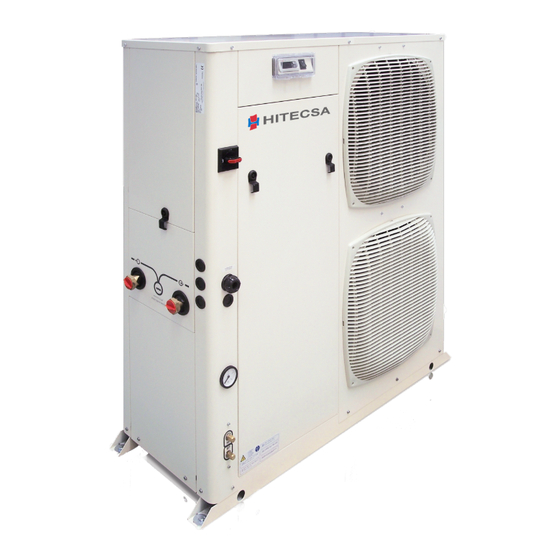
- Page 1 AIR COOLED WATER CHILLERS AND HEAT PUMPS 7,05 kW - 34,1kW EWFAIB 20.1, 25.1, 30.1 12.13 Ref. 207384 rev.100...
-
Page 2: Table Of Contents
5.3 Checking the operation ............20 12.1 Generalities ................47 5.4 Delivery to the customer ..........20 & 21 6 - EWFAIB CONTROL 6.1 Control of EWFAIB units, single compressor, variable speed ..............21 6.2 Keypad functions ............21 & 22 6.3 Alarms ................22... -
Page 3: Foreword
1 - Foreword 1.1 Introduction 1.3 Emergency stop / Normal stop Units, manufactured to state-of-the-art design and implementation The emergency stop of the unit can be enabled using the master standards, ensure top performance, reliability and fitness to any type switch on the control panel (move down the lever). -
Page 4: Safety
2 - Safety 2.1 Foreword The guards of the fans (only for units provided These units must be installed in conformity with the with air heat exchangers) must be always provisions of Machinery Directive 2006/42/EC, Low Voltage mounted and must never be removed before Directive 2006/95/EC, Pressure Vessels Directive 97/23/ DANGER de-energising the appliance. -
Page 5: Definitions
2 - Safety Use tools in a good state of repair; be sure to have understood the 2.2 Definitions instructions before using them. OWNER: means the legal representative of the company, body or individual who owns the plant where unit has been installed; he/she Be sure to have removed all tools, electrical cables and any other has the responsibility of making sure that all the safety regulations objects before closing and starting the unit again. -
Page 6: Precautions During Maintenance Operations
2 - Safety Periodically check the board’s internal wiring. Make sure that on-off remote controls are inhibited. Do not use cables having an inadequate section or flying Wear suitable personal protective equipment (helmet, safety connections, even for limited periods of time or in an emergency. gloves, goggles and shoes etc.). -
Page 7: Safety Labels
2 - Safety 2.7 Safety labels Identification of the refrigerant - External door Use of filter and flow switch - Adjacent to fittings E’OBBLIGATORIO L’USO DI FILTRO E FLUSSOSTATO ACQUA USARE SOLO THE USE OF FILTER AND FLOW SWITCH IS MANDATORY EL USO DEL FILTRO Y DEL INTERRUPTOR DE FLUJO ES OBLIGATORIO L’UTILISATION DU FILTRE ET DU FLUXOSTAT EST OBLIGATOIRE R 410A... - Page 8 2 - Safety Start-up warning - Outside the door Grounding connection on the Read the instruction on the electrical board, of the electrical board electrical board adjacent to the connection Fitting identification - Adjacent to fittings Sequence phase control on the electrical board ATTENZIONE QUESTO COMPRESSORE RICHIEDE UN CORRETTO SENSO DI ROTAZIONE RISPETTARE LA CORRETTA...
- Page 9 2 - Safety 2.8 Safety regulations REFRIGERANT DATA SAFETY DATA: R410A Toxicity Low. If sprayed, the refrigerant is likely to cause frost burns. If absorbed by the skin, the danger is very limited; it may cause a slight irritation, and the liquid is degreasing. Unfreeze the affected skin with water. Contact with skin Remove the contaminated clothes with great care - in the presence of frost burns, the clothes may stick to the skin.
- Page 10 2 - Safety 2.8 Safety regulations (continued) REFRIGERANT DATA SAFETY DATA: R410A Do not inhale concentrated vapours. Their concentration in the atmosphere should not exceed the minimum preset values and should be maintained below the professional threshold. Being more weighty General precautions than the air, the vapour concentrates on the bottom, in narrow areas.
-
Page 11: Safety Regulations
2 - Safety 2.8 Safety regulations (continued) LUBRICANT OIL DATA SAFETY DATA: POLYESTER OIL (POE) Classification Not harmful. May cause slight irritation. Does not require first aid measures. It is recommended to follow usual personal hygiene measures, including washing the exposed skin with soap and water several times a day. Contact with skin It is also recommended to wash your overalls at least once a week. -
Page 12: Transport, Handling And Storage
3.2 Handling EWFAIB units are designed to be lifted from above, by means of cables and eyebolts. A spacer shall be arranged between the cables in order to prevent them from damaging the unit (see the figure aside). -
Page 13: Anchoring
3 - Transport, Handling and Storage Never store the units in a room where temperature is above Until the unit is ready for operation, do not 50 °C (R410A units) or where the units are directly exposed to remove the plastic envelope and the coil the sunlight. -
Page 14: Installation
4 - Installation 4.1 Installation Site 4.2 External Water Circuit The external water circuit shall guarantee a Before installing the unit, make sure that constant water flow rate through the circulating the building structure and/or the supporting refrigerant/water heat exchanger (evaporator) surface can withstand the weight of the under steady operating conditions and in case device. - Page 15 4 - Installation External water circuit HYDROKIT INLET OUTLET COMPONENTS 1 Plate heat exchanger 2 Pump SAFETY/CONTROL DEVICES 3 Draining valve Inlet water temperature sensor 4 Water buffer tank Outlet water temperature sensor 5 Water filter Water differential pressure switch (105 mbar) 6 Automatic water charging valve Vent valve 7 Pressure expansion tank...
-
Page 16: External Water Circuit
4 - Installation 4.5 Water buffer tank Before filling the installation, remove any The accumulation tank which has been designed to be mounted on impurity, such as sand, crushed stones and units is complete with all the hydraulic and electrical components welding scales, coating drops and any other required for the correct operation of the system. -
Page 17: Power Supply
4 - Installation CAUTIONS 4.6 Power supply The unit + tank system shall be equipped with a filter. Use the filter + union as it is shown by Figure 1. Before carrying out any operations on the electrical system, make sure that the unit is Figure 1 deenergized. - Page 18 4 - Installation Antifreeze Resistance Wiring Storage Kit (112 l) - Dimensional Data Front view Side view Top view 4 holes Ø9 62.5 62.5 1352 1477 Water inlet on the plant side Ø1 ½” gas male Water outlet on the chiller side Ø1 ½” gas male Water filling ؽ”...
-
Page 19: Electrical Connections
4 - Installation 4.7 Electrical connections For 3-phase systems, check also that the unbalance between the phases does not exceed 2%. To perform this check, measure the The unit must be installed on site according to the usual differences between the voltage of each phase couple and their mean procedures and standards applicable in the place of value during operation. -
Page 20: Electrical Connections
4 - Installation Electrical Connections... -
Page 21: Start-Up
5 - Start-up Check the operation of all the external equipment, and make sure The unit must be started for the first time by that the control devices of the plant are properly calibrated. personnel suitably trained by one of Authorised Start the pump and check that the water flow is correct. -
Page 22: Ewfaib Control
6.1 Control of EWFAIB units, single compressor, In the “menu” mode: variable speed – Navigate upwards in the EWFAIB units are provided with a microprocessor card which is fully menu (level sub-level programmed by default for the control of a heat pump unit. -
Page 23: Alarms
6 - EWFAIB Control Indicator light 6.4 Menus The display comprises several menus. Some have unrestricted On= alarm active, check the access and one (the Manufacturer menu) is password protected. alarm codes. 6.4.1 General menu On= compressor operating. Flashing= compressor stand-by to start up 6.3 Alarms... - Page 24 6 - EWFAIB Control 6.4.2 Set menu 6.4.3 tP menu...
- Page 25 6 - EWFAIB Control 6.4.4 I-O menu...
- Page 26 6 - EWFAIB Control 6.4.5 Err menu 6.4.6 LOG menu 6.4.7 PAr menu...
- Page 27 6 - EWFAIB Control 6.4.8 PSS menu...
-
Page 28: Menus
6 - EWFAIB Control 6.4.9 OHr menu 6.5 Starting the appliance 6.5.1.2 Water compensation rule After checking all the electrical connections and making any The H09 setting is used to pre-adjust the water law. rectifications as required, proceed with starting up the installation. - Page 29 6 - EWFAIB Control 6.5.1.3 Operating condition...
- Page 30 6 - EWFAIB Control 6.5.1.4 Water compensation (heating operation) Example: HEA= heating water set-point before correction 35 [°C]. H14= Max OAT with min LWT 15 [°C]. H15 = temperature on OAT 10 [K]. H16 = temperature on LWT 15 [K].
-
Page 31: Parameters List
6 - EWFAIB Control 6.6 Parameters list PARAMETER DESCRIPTION UNIT DEFAULT TYPE Heating set-point °C Actual heating set-point °C Cooling set-point °C Actual cooling set-point °C Neutral band ON-OFF Operation mode (heating/cooling) Heating Return water temperature °C Leaving water temperature °C... - Page 32 6 - EWFAIB Control PARAMETER DESCRIPTION UNIT DEFAULT TYPE Software release 0= air conditioning (AC) PAR-CnF Type of application 1= cool/heat floor (CHF) 2= fixed water set point (FIX) DCI size 0= air conditioning (AC) Selection of type of application...
-
Page 33: Alarm List
6 - EWFAIB Control 6.7 Alarm list CODE DESCRIPTION ALARM ORIGIN Return water temperature probe failure Leaving water temperature probe failure Outdoor air temperature probe failure Outdoor coil temperature probe failure Water flow / pump motor alarm Fan motor alarm... -
Page 34: Product Description
Fans Control EWFAIB heat pump models can warm up water at a temperature between 20 °C and 50 °C for EWFAIB 20-35 and 55 °C for EWFAIB 40-75. All models are equipped with a single-phase voltage fan speed controller using the principle of phase control to adjust the effective All units can operate with a double set point. - Page 35 7 - Product Description 7.2 Accessories EWFAIB 20-35 Water Gauge It is assembled on the unit as a standard. Water Filter Pump 1-1/2” filter is included in the supplied equipment. Min. 100 kPa head pressure pump is mounted as a standard in the It is supplied loose and has to be mounted by the customer.
-
Page 36: Accessories
7 - Product Description Airway Packaging Fan speed control -10 °C Complete wooden package for units without refrigerant and with Fan speed control is available as accessory to allow the chiller to nitrogen precharge. No refrigerant charge is shipped loose with operate down to external air temperature. - Page 37 7 - Product Description 7.3 Refrigerant flow diagram - EWFAIB 20 to 35 - R410A INVERTER UNIT CONTROL CONTROL COMPONENTS 1 Compressor tandem scroll type 2 4-way valve 3 Air cooled condenser 4 Biflow filter drier 5 Sight glass 6 Biflow thermostatic expansion valve...
-
Page 38: Technical Data
8 - Technical Data 8.1 Hydraulic Features Units EWFAIB 20-35 25-30 25-30 Water flow rate [l/s] unit external static pressure curves. plate heat exchanger water pressure drop curves. 20-25-30 Water flow rate [l/s]... -
Page 39: Physical Data
8 - Technical Data 8.2 Physical data EWFAIB Power supply V/ph/Hz 400/3+N/50 Number of refrigerant circuits Part load steps Stepless REFRIGERANT Type R410A Charge (1) COMPRESSOR Type Scroll (BLDC Motor) Number Start-up type Inverter Oil type EVAPORATOR Type Plate Number... -
Page 40: Electrical Data
8 - Technical Data 8.3 Electrical data EWFAIB Power supply V/ph/Hz 400 ± ( 10%)/3+N/50 Maximum power input 12.0 14.3 14.3 Maximum current input 24.9 30.1 30.1 Start-up corrent External fuses Max cable section (*) HEAT EXCHANGER RESISTANCE Power supply V/ph/Hz 230 ±... -
Page 41: Dimensional Drawings
8 - Technical Data 8.4 Dimensional Drawings Front view Side view Ø30 Ø30 Top view 1408 1441 1477 Water inlet Ø1 ½” gas male Water outlet Ø1 ½” gas male Auxiliary lines Electrical power supply Sight glass inspection High pressure tap Low pressure tap Gauge kit (optional) Main switch... -
Page 42: Space Requirements
8 - Technical Data 8.5 Space Requirements 200 mm 200 mm 200 mm 400 mm 800 mm... -
Page 43: Maintenance
9 - Maintenance Carefully read the “Safety” section of this manual before carrying out any maintenance operations. Operations Do not discharge the refrigerant into the atmosphere while the refrigeration circuits Check the temperature • are being drained. Use appropriate recovery of the leaving fluid equipment. -
Page 44: Refrigerant Charge
9 - Maintenance 9.3 Refrigerant charge 9.5 Condenser The condenser’s coils consist of copper pipes and aluminium fins. Do not inject refrigerant liquid into the LP side In the presence of leaks caused by any damage or shock, the coils of the circuit. -
Page 45: Sight Glass
9 - Maintenance 9.8 Sight glass Overheating calculation (S): S = Tse - Tsa The sight glass is used for inspecting the refrigerant flow and the humidity % of the refrigerant. The presence of bubbles indicates that Overheating is regulated through the driver. the dehydrating filter is clogged or the charge insufficient. -
Page 46: Troubleshooting
10 - Troubleshooting The table below lists the anomalies of operation of the unit, the relevant causes and the corrective measures. For anomalies of any other type or not listed, contact one of authorised Service Centre for technical assistance. Anomaly Cause Operation The unit continues... -
Page 47: Spare Parts
11 - Spare Parts 11.1 Spare part list The table below shows the list of spare parts recommended during the first two years of operation. Component Number High pressure switch Differential water pressure switch High pressure transducer Low pressure transducer Expansion valve Gas filter Four-way valve... -
Page 48: Dismantling, Demolition And Scrapping
12 - Dismantling, Demolition and Scrapping After draining operations, the piping of the hydraulic networks can be disconnected and disassembled. During the draining of the refrigeration circuits, do not let the refrigerant overflow in Once they have been disconnected as specified, the packaged units the surrounding atmosphere. - Page 49 Reserved the right to make changes without previous notice. HIPLUS AIRE ACONDICIONADO S.L. C/ Masia Torrents, 2 Tel. 938 934 912 Fax 938 939 615 08800 VILANOVA I LA GELTRÚ- BARCELONA –ESPAÑA Internet: http://www.hitecsa.com E-mail: info@hitecsa.com 12.13 Ref. 207384 rev.100...
Need help?
Do you have a question about the EWFAIB and is the answer not in the manual?
Questions and answers