SerVision CVG-M Installation Manual
Hide thumbs
Also See for CVG-M:
- Installation manual (35 pages) ,
- Configuration and management manual (241 pages)
Table of Contents
Advertisement
Quick Links
Advertisement
Table of Contents

Related Manuals for SerVision CVG-M


Summary of Contents for SerVision CVG-M
-
Page 1: Installation Guide
CVG-M Installation Guide November 2014... - Page 2 © 2014 SerVision Ltd. All rights reserved. Notice Information in this document is subject to change without notice. SerVision Ltd. assumes no responsibility for any errors that may appear in this manual. Companies, names and data used in examples herein are fictitious unless otherwise noted.
-
Page 3: Table Of Contents
Connecting the Cellular Antenna Inserting the SIM Card Connecting the GPS Antenna Connecting the CVG-M to a Power Source Connecting the Wire Connector to the Unit Connecting the Unit to an Electrical Outlet Connecting the CVG-M to a Vehicle Battery... -
Page 4: Introduction
Once the CVG-M has been installed as explained in this guide, it must be configured. Configuration is performed by connecting to the CVG-M unit using a PC that is on the same network as the unit (or connected to the unit directly using a LAN cross cable) and opening the unit’s configuration utility in a browser. -
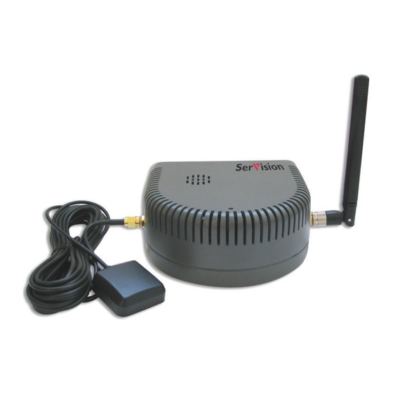
Page 5: The Cvg-M Package
SerVision CVG-M Installation Guide The CVG-M Package The CVG-M package contains the following items: Item Description Illustration CVG-M unit Video Gateway Ethernet (LAN) Connects the unit to a PC (or a cable cable-based local network) RS232/485 serial Connects PTZ controllers to the... - Page 6 NOTE: The power-supply cable, the power-connector cable, and the power cord with cigarette-lighter connector are not required for operation of the CVG-M in a vehicle, because the unit is hard-wired to the vehicle battery when it is installed. Typically, the CVG-M unit is configured in an office setting before it is installed, and for that the power-supply and power-connector cables are used.
-
Page 7: Additional Equipment
CVG-M Installation Guide Additional Equipment One or two video cameras should be connected to the CVG-M. You must acquire the cameras you require; they are not included in the CVG-M package. For information about camera compatibility and about connecting the cameras to the unit, see Connecting Cameras, page 14, or consult your vendor. -
Page 8: Installing The Cvg-M System
Selecting a Location for the Unit The CVG-M unit should be placed on a flat surface such as a shelf. (It is not designed for mounting directly on a wall.) If it is being installed in a vehicle, the unit should be installed in a cool and ventilated location, protected from direct sunlight and water (including liquids used to clean the inside of the vehicle), and as far away from humidity as possible. -
Page 9: Preventing Overheating
When choosing a location for the CVG-M, bear in mind that the unit must be connected to a power source and a LAN or a PC, and that other devices (cameras, sensor, etc.) must be connected both to it and to power sources. If... - Page 10 Figure 2: Video Gateway installed in an insulated container and attached to the back of a seat in a car In buses and trains, the CVG-M can be installed in an air-conditioning duct or in the compartment above the driver's seat.
-
Page 11: Diagrams Of Connectors
SerVision CVG-M Installation Guide Diagrams of Connectors The rear and sides of the CVG-M unit contain the following connectors. SIM card MicroSD Card 12VDC Power Out SIM indicator GPS Antenna Modem Antenna Audio In (Ain1) Audio Out (Aout) Video In (Vin2) -
Page 12: Supplying Power To Devices Connected To The Unit
All devices that draw their power through the 12VDC Power Out connector on the CVG-M are also turned off when the CVG-M shuts down, because they do not receive any power from the unit. If you want devices that are directly connected to the vehicle battery to also shut down when the vehicle ignition is off, you should route the power supply through the activator connector (Out1) on the CVG-M unit, as illustrated below. -
Page 13: Transforming The Supplied Voltage To 12V
7.2W. NOTE: You can convert Amps to Watts using the following formula: Volts * Amps = Watts 12 * 0.25 = 3 For example, a 12V device that operates at 250 mA consumes 3 Watts: Installing the CVG-M System... -
Page 14: Configuring The Power-Supply Activator
When the power supply to devices is routed through the activator connector, as described above, the activator must be configured correctly in the CVG-M's configuration: the Activator Type of the activator must be set to Bypass, as in the illustration below. (For additional information about configuring the activator, please refer to the Embedded Video Gateway System Guide, under Configuring Sensor and Activator Settings.) -
Page 15: Connecting Devices To The Cvg-M
This section explains how to connect devices such as cameras or a sensor to the CVG-M unit. NOTE: If you are connecting devices to a CVG-M in a vehicle, make sure that all the devices are designed to function properly under mobile conditions (temperature range, vibrations, power supply, etc), that they... - Page 16 2. If two PTZ cameras are connected to the unit, configure each camera to use a different ID. For information about how to do this, refer to the camera documentation. 3. Connect the RS232/485 adapter to the RS232/485 connector on the side panel of the unit. Connecting Devices to the CVG-M...
-
Page 17: Connecting Sensors
1. Install the sensor or switch in its desired location in accordance with the manufacturer's instructions. 2. Connect the two wire contacts of the sensor or switch to the In1 connector on the rear panel of the CVG-M, as illustrated in figure 13. Insert the wires into the connectors and tighten the screws below each connector to hold the wires in place. -
Page 18: Connecting Sensors Using An Adam Module
Connecting Sensors Using an ADAM Module If you want to connect additional dry sensors to the CVG-M, you can do so by connecting an ADAM Data Acquisition Module to the unit. Up to 16 additional dry sensors can then be connected to the unit through the ADAM module. - Page 19 Data- (R) +Vs (R)+Vs (B) GND (B)GND 4. Connect the ADAM-4520 isolated converter to the RS232/485 connector on the rear panel of the CVG-M unit in one of the following ways: If you are not connecting any RS485 PTZ controllers to the unit, using the 9-pin flat ribbon cable, connect the RS232 connector of the ADAM-4520 converter directly into the RS232/485 connector.
- Page 20 Note: You may be able to supply power to the modules by connecting it to the 12VDC Power Out connector on the rear panel of the unit (see Using the 12VDC Power Out Connector, page 36). Connecting Devices to the CVG-M...
-
Page 21: Connecting An Activator
1. Install the activator in its desired location in accordance with the manufacturer's instructions. 2. Connect the two contacts of the activator to the Out1 connector on the CVG-M, as illustrated in figure 19. It does not matter which wire you connect to each contact. -
Page 22: Connecting Sensors And Activators Using An Ia Relay Board
Connecting Sensors and Activators Using an IA Relay Board If you want to connect additional dry sensors and/or activators to the CVG-M, you can do so by connecting an Intelligent Appliance IA 3126-2 relay board to the unit. Up to 16 additional dry sensors and 16 additional activators can then be connected to the unit through the relay board. -
Page 23: Connecting A Microphone
1. Set the ID of the relay board to 0. (For information about how to do this, consult the relay-board documentation.) 2. Connect the relay board to the RS232/485 connector on the rear panel of the CVG-M unit in one of the following ways: ... -
Page 24: Connecting A Speaker Or Headphones
CVG-M. It is primarily useful if you want to view video when the user is near the unit. For example, if the CVG-M is set up in a bus, the driver can use a CCTV monitor to keep tabs on parts of the bus that cannot been seen from the driver’s seat. - Page 25 1. Install the monitor in its desired location. 2. Connect the Video In connector of the monitor to the TV Out connector of the CVG-M, using a cable with an appropriate connector (BNC or RCA) for the Video In connector of the monitor on one end, and a BNC male connector on the other end.
-
Page 26: Connecting A Switch
Embedded Video Gateway System Guide. Connecting Multiple Monitors If you wish, you can connect multiple CCTV monitors to the CVG-M. For example, you may wish to have one monitor beside the driver’s seat and another beside the conductor’s seat. To connect multiple monitors, you must use video splitters to split the connection. Bear in mind, however, that the image quality in each of the monitors will be slightly degraded. -
Page 27: Connecting The Cvg-M To A Network
Embedded Video Gateway System Guide. LAN Connection You can connect the CVG-M to a cable-based LAN. When the unit is connected to a LAN, it cannot connect to a cellular network. - Page 28 1. Using the tip of a paper clip, a ball-point pen, or a similar item, firmly press the release button at the side of the SIM-card slot on the rear of the CVG-M. The SIM-card holder pops partway out of the slot.
-
Page 29: Connecting The Gps Antenna
Connecting the GPS Antenna A GPS receiver is built into the CVG-M unit. When the GPS antenna is connected to the unit, this receiver can be used to track the location of a vehicle in which the CVG-M is installed. -
Page 30: Connecting The Cvg-M To A Power Source
CVG-M Installation Guide Connecting the CVG-M to a Power Source The CVG-M can be connected either to an electrical outlet using the supplied power-supply cable, or to the ignition of a vehicle, using the supplied power cord. Once it is connected, the unit starts up automatically. During the start-up process, the Power LED on the top of the unit flashes at various intervals. -
Page 31: Connecting The Unit To An Electrical Outlet
The CVG-M Package, page 4). To connect the CVG-M to a standard electrical outlet: 1. Connect the power-connector cable to the power-supply cable. 2. If a wire connector is connected to the Power connector on the unit, unscrew the screw holding it in place, and remove it. -
Page 32: Connecting The Cvg-M To A Vehicle Battery
To connect the CVG-M to a vehicle battery: 1. If the wire connector is not plugged into the Power connector on the unit, plug it into the Power connector on the rear panel of the unit, and tighten the screws to secure it. - Page 33 Connect to positive (+) Connect to battery connector the ignition Connect to negative (-) battery connector connector (-) connector (+) connector Figure 34: Connecting the CVG-M to the vehicle battery and the ignition Connecting the CVG-M to a Power Source...
- Page 34 Figure 35: Connecting the IGN connector to the (+) connector when a connection to the ignition is not required To connect the CVG-M to a vehicle’s cigarette lighter: Use the supplied power cord to connect the Power connector on the rear panel of the unit to the vehicle’s cigarette lighter.
-
Page 35: Appendix 1: Removing The Microsd Card
Appendix 1: Removing the MicroSD Card The CVG-M unit stores all recorded video and event information on a standard microSD card. The unit is supplied with a 4 GB microSD card. You can remove this card from the unit in order to copy video files from it and/or replace it with a different microSD card. - Page 36 SerVision CVG-M Installation Guide To insert a microSD card into the unit: Hold the card as illustrated below and push it gently into the card slot until it clicks into place. Hold the card on this edge, with the lettering facing up.
-
Page 37: Appendix 2: Using The 12Vdc Power Out Connector
The CVG-M can supply power directly to cameras and other devices via the 12VDC Power Out connector on the rear panel of the unit. However, only a limited amount of power can be supplied by the CVG-M in this way. If the devices connected to the 12VDC Power Out connector draw a total of more than 250 mA at one time, the unit may overheat or otherwise malfunction. - Page 38 POB 45205 Jerusalem 91450 Israel Tel: +972-2-535 0000 • Fax: +972-2-586 8683 www.servision.net • info@servision.net CVG-M Installation Guide...
Need help?
Do you have a question about the CVG-M and is the answer not in the manual?
Questions and answers