Table of Contents
Advertisement
Quick Links
Advertisement
Table of Contents

Related Manuals for SerVision IVG400-N


Summary of Contents for SerVision IVG400-N
- Page 1 IVG400-N Quick-Start Guide Preliminary Version July 2016 Introduction...
- Page 2 © 2016 SerVision Ltd. All rights reserved. Notice Information in this document is subject to change without notice. SerVision Ltd. assumes no responsibility for any errors that may appear in this manual. Companies, names and data used in examples herein are fictitious unless otherwise noted.
-
Page 3: Table Of Contents
Connecting a PC to the IVG400-N Unit Opening WebMax Overview of the WebMax Interface Modifying Settings General Settings Network Settings Modifying the Ethernet IP Address of the IVG400-N Unit Configuring a WiFi Connection Configuring Cellular Connections Configuring the Cameras Main and Sub Streams Video Recording Settings... -
Page 4: Introduction
PC. Basic instructions for configuring the IVG400-N are included in this guide. Client software is used for accessing the IVG400-N unit remotely in order to view video and events and control the system in various ways. SerVision’s next-generation client application for PCs, SVCentral, offers full support for digital video streams created by IVG400-N. -
Page 5: The Ivg400-N Package
SerVision IVG400-N Quick-Start Guide The IVG400-N Package The IVG400-N package contains the following items: Item Description Illustration IVG400-N unit Video Gateway Ethernet (LAN) Connects the unit to a PC or a cable local network WiFi antenna Enables the built-in WiFi adapter... - Page 6 NOTE: The power-supply cable, the power-connector cable, and the power cord with cigarette-lighter connector are not required for operation of the IVG400-N in a vehicle, because the unit is hard-wired to the vehicle battery when it is installed. Typically, IVG400-N units that are installed in vehicles are configured in an office setting before they are installed.
-
Page 7: Additional Equipment
IVG400-N Quick-Start Guide Additional Equipment Up to four IP video cameras can be connected to the IVG400-N. Although cameras are not included in the IVG400-N package, at present, you must acquire the cameras you require from SerVision, because only one model is currently supported, and it is preconfigured at SerVision. -
Page 8: Diagrams Of Connectors
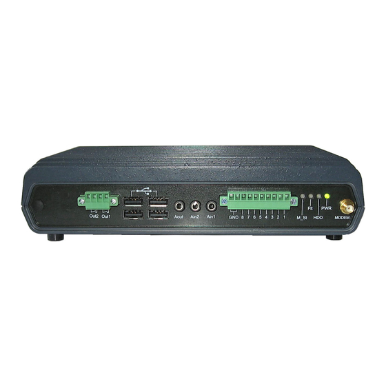
Diagrams of Connectors IVG400-N has connectors on both the front and back panels, as described below. Front Panel The connectors and indicators of the front panel of the IVG400-N unit that are currently supported are described below. Activators USB ports... -
Page 9: Rear Panel
Box facing up Figure 4: GPS antenna cable LEDs Status indicators Rear Panel The connectors of the rear panel of the IVG400-N unit that are currently supported are described below. Diagrams of Connectors... - Page 10 When a standard HDMI monitor is connected, you can see live video streams from the system on it. If you connect a mouse and keyboard to the IVG400-N unit, you can also configure the unit from the monitor. WiFi antenna...
-
Page 11: Installing The Ivg400-N Unit
Installing the IVG400-N Unit The IVG400-N unit can be installed vertically or horizontally. If it is installed vertically, or it is installed on a moving platform such as a vehicle, it must be mounted using the supplied supports. If it is installed in a stationary location, it can be placed horizontally on a stable flat surface such as a table or shelf, and does not necessarily have to be secured. -
Page 12: Mounting The Unit
Preventing Overheating IVG400-N units should be installed in the passenger compartment in a location that is cooled by the vehicle's air- conditioning when the air conditioner is on. Ideally, the units should be installed in insulated plastic containers with built-in fans. - Page 13 Figure 9: Video Gateway installed in an insulated container attached to the back of a seat in a car In buses and trains, the IVG400-N can be installed in an air-conditioning duct or in the compartment above the driver's seat.
- Page 14 Figure 10: Video Gateway installed in the air-conditioning duct of a bus Figure 11: Video Gateway installed in the compartment above the driver's seat in a bus NOTE: The Video Gateways in the pictures above are not IVG400-Ns, but the principles are the same for IVG400-Ns. Installing the IVG400-N Unit...
-
Page 15: Connecting The Unit To External Networks
You can connect the router to a LAN, a cellular network, and/or a WiFi access point. This section explains how to set up the hardware so that the router can be used by the IVG400-N unit to connect to these networks. In order for the unit to connect to these networks, it must also be configured as explained under Network Settings, page 33. - Page 16 SerVision IVG400-N Quick-Start Guide Storage medium in compartment cover SIM card slot Wires connecting storage medium Figure 13: Compartment opened 3. Insert the SIM card in the slot. 4. Carefully close the compartment, making sure the wires connecting the storage medium are not caught in the opening, and turn the key to lock the compartment.
-
Page 17: Connecting The Ivg400-N To A Power Source
Mobile Installations Typically, even if the IVG400-N is going to be installed in a vehicle, the unit is configured in an office setting and then installed in the vehicle. The power-supply and power-connector cables are used to connect the unit to a standard electric outlet for configuration. -
Page 18: Connecting The Unit To A Vehicle Battery
Connecting the Unit to a Vehicle Battery Normally, when the IVG400-N is installed in a vehicle, the unit is connected to the vehicle battery and to the ignition using 16 AWG cable (not supplied). This can be done in one of two ways: •... - Page 19 To connect the IVG400-N to the vehicle battery: 1. If the wire connector is not in the Power connector on the rear of the unit, insert it and tighten the screws to secure it.
- Page 20 Connect to negative (-) battery connector connector (-) connector (+) connector Figure 18: Connecting the IVG400-N to the vehicle battery and the ignition Connect to positive (+) battery connector Connect to negative (-) battery connector Wire connecting to (+)
-
Page 21: Stationary Installations
To connect the unit to a power source: • .Connect one end of the power-supply cable to the Power connector on the rear panel of the unit, and the other end of the cable to a standard wall outlet. Connecting the IVG400-N to a Power Source... -
Page 22: Setting Up The Svcentral Client Application
SVCentral and open it from there. This chapter explains how to install SVCentral on the PC you will use to connect to the IVG400-N, and provides a brief overview of SVCentral’s interface. For additional information about SVCentral, please refer to the SVCentral User Guide. -
Page 23: Overview Of The Main Svcentral Window
SerVision IVG400-N Quick-Start Guide Figure 22: Main SVCentral window the first time it is opened Overview of the Main SVCentral Window The main window of the SVCentral interface is divided into the following regions: • Main menu: Provides access to configuration and display options, as well as information about the application •... - Page 24 SerVision IVG400-N Quick-Start Guide Right Right-panel tabs Placements panel (Video tab selected) toolbar Main Menu Gateways toolbar Left panel Status bar Figure 23: Regions of the main SVCentral window Setting Up the SVCentral Client Application...
-
Page 25: Basic Configuration
Connecting a PC to the IVG400-N Unit At present, in order to open the WebMax, your PC must be connected directly to the IVG400-N unit by means of a network cable. In addition, you must temporarily change the network settings of your PC to match those used by the IVG400-N unit. - Page 26 SerVision IVG400-N Quick-Start Guide Figure 25: Network Connections window 3. Right-click the network connection you are using to connect to the IVG400-N, and then select Properties. The Connection Properties window opens. Figure 26: Connection Properties window 4. In the list of items, double-click Internet Protocol Version 4 (TCP/IPv4). The...
-
Page 27: Opening Webmax
Opening WebMax Once your PC is connected to the IVG400-N unit as described above, you can open its WebMax configuration utility. You can do this in one of two ways: through SVCentral or directly in your browser. (Regardless of which method you use, you will end up with WebMax open in the browser.) - Page 28 Note: The default user name and password for client access, , are filled in by default. You anonymous guest can change these values in WebMax if you wish. Figure 30: Gateway Info dialog box with the IP address and port of the IVG400-N entered Basic Configuration...
- Page 29 IVG400-N Quick-Start Guide 3. Click OK. The IVG400-N is added to the list, and SVCentral attempts to connect to it. When it succeeds, the IP and port are replaced with the name of the unit, as it appears in its configuration, and an Expand button ( ) appears to the left of the name.
- Page 30 SerVision IVG400-N Quick-Start Guide Figure 34: WebMax login page 5. Under User Name, enter ; under Password, enter svuser servconf Note: These are the default user name and password for configuration access. You can change these values in WebMax if you wish.
-
Page 31: Overview Of The Webmax Interface
SerVision IVG400-N Quick-Start Guide Overview of the WebMax Interface WebMax consists of screens that are displayed on the right side of the window and a main menu in a sidebar on the left side of the window. A status bar at the top of the screen displays, among other things, the name of the IVG400-N. - Page 32 SerVision IVG400-N Quick-Start Guide Update Figure 37: Update button The changes are saved in a temporary cache on the unit. 3. To modify additional settings, in the main menu, select the relevant screen and make the changes as necessary. Click Update in each screen when you are finished modifying its settings. (You can continue modifying the settings in the same screen, if necessary;...
-
Page 33: General Settings
(see page 8). Ignition For mobile IVG400-N units: Select this option if you want the unit to power down automatically whenever the vehicle ignition is turned off. If you do not select this option, the unit operates continuously as long as it has a power supply. For... -
Page 34: Network Settings
Modifying Settings, page 30. Network Settings The IVG400-N unit contains six Network Interface Cards (NICs): two Ethernet NICs and four PoE NICs. In addition, it contains a cellular interface and a WiFi interface. The settings for all of these network connections are... -
Page 35: Modifying The Ethernet Ip Address Of The Ivg400-N Unit
Configuring a WiFi Connection If you want the IVG400-N to connect to a LAN through a wireless access point (WiFi), you can configure it to do so as explained below. The unit will attempt to connect to the specified access point whenever it is in range. The access point does not have to be in range of the unit when you configure the WiFi settings. - Page 36 2. Under Type, select one of the following: • • • Static: Select this option if you want to set the IVG400-N’s IP address in the WiFi network manually by assigning it a fixed IP in your network. • •...
-
Page 37: Configuring Cellular Connections
The system can connect to a GSM or a CDMA network. In order for it to connect to a GSM network, an appropriate SIM card must be installed in the IVG400-N (see Connecting the Unit to External Networks, page 14). For either type of cellular network, the settings must be configured as explained below. -
Page 38: Configuring The Cameras
10.0.0.10, 10.0.0.11, 10.0.0.12, and 10.0.0.13 (if you purchased four of these cameras). The cameras should be connected to the PoE connectors (PoE1–PoE4) on the rear panel of the IVG400-N unit. At present, the unit is also preconfigured to work with the cameras when they are plugged into the PoE connectors. It does not matter which camera is connected to each connector. -
Page 39: Main And Sub Streams
7.3 GB of disk space would be required per hour. Thus, if a 256 GB SSD is installed on the IVG400-N, it would be able to store a maximum of 35 hours of HD video. By contrast, if there are 2 events in an hour, and the recorder records 190 seconds for each event, only 97.28 MB (about 0.1 GB) of disk space are... - Page 40 SerVision IVG400-N Quick-Start Guide Figure 47: Camera Summary screen Camera Summary 2. In the screen, select Add Camera. A camera-configuration screen opens. Figure 48: Camera-configuration screen (new camera) 3. In the General Information area, fill in the fields as follows:...
- Page 41 Transcoders are used for the recording, with one exception: When a client is receiving a Sub stream from the IVG400-N, the quality settings of that Sub stream are used. (This is because only one Sub stream can be captured at a time.)
- Page 42 Note: The warning, “the first transcoder must be set with the same parameters as the camera” is not relevant to the Codex cameras currently supplied by SerVision. 6. Select Update to save the changes to the temporary cache. The new camera is added to the list of cameras. For information about implementing the changes permanently, see Modifying Settings, page 30.
-
Page 43: Configuring Sensors And Activators
Up to eight dry-contact external sensors and up to two external activators can be connected to the IVG400-N unit. In addition, the built-in G-force... - Page 44 SerVision IVG400-N Quick-Start Guide Figure 53: Sensor Settings screen (sensor disabled) 3. Select the Enable checkbox. The fields required to configure the settings are added to the screen. Figure 54: Sensor Settings screen (sensor enabled) Basic Configuration...
- Page 45 SerVision IVG400-N Quick-Start Guide Figure 55: Activator Settings screen (activator enabled) 4. Fill in the fields as follows: Field Description Description Enter a name for the device. closed Polarity Select Reverse if the normal, inactive state of the sensor is –...
-
Page 46: Configuring A G-Force Sensor
Configuring a G-Force Sensor G-Force sensors, which are built into IVG400-N units, detect extreme or sudden motion. They can be configured to be more or less sensitive, as required. At their highest sensitivity, they can even detect driver behavior that is somewhat erratic. - Page 47 You may have to experiment with different settings to see which is ideal for the particular vehicle the IVG400-N is installed in.
-
Page 48: Viewing Video From The Ivg400-N In Svcentral
Viewing Video from the IVG400-N in SVCentral Once you have set up and configured the IVG400-N unit as described in this guide, you can view video from it in SVCentral. The PC on which SVCentral is running does not have to be connected directly to the IVG400-N unit any more. - Page 49 SerVision IVG400-N Quick-Start Guide Figure 61: Video stream playing in camera pane Viewing Video from the IVG400-N in SVCentral...
- Page 50 POB 45205 Jerusalem 91450 Israel Tel: +972-2-535 0000 • Fax: +972-2-586 8683 www.servision.net • info@servision.net IVG400-N Quick-Start Guide...
Need help?
Do you have a question about the IVG400-N and is the answer not in the manual?
Questions and answers