
Related Manuals for SerVision HVG400


Summary of Contents for SerVision HVG400
- Page 1 Embedded Video Gateway System Guide Configuration and management guide for SerVision HVG400, UVG400, MVG200, MVG400, CVG, and CVG-M Video Gateway models 2015...
- Page 2 © 2015 SerVision Ltd. All rights reserved. Notice Information in this document is subject to change without notice. SerVision Ltd. assumes no responsibility for any errors that may appear in this manual. Companies, names and data used in examples herein are fictitious unless otherwise noted.
-
Page 3: Table Of Contents
SerVision Embedded Video Gateway System Guide Table of Contents Getting Started About this Guide About Client Software Before You Begin Installing SVMultiClient Opening the Configuration Utility Overview of the Interface Top-Level Menu Options Status Bar Using the Configuration Utility Opening the Configuration Remotely... - Page 4 SerVision Embedded Video Gateway System Guide Defining a New Schedule Row Audio Settings Configuring Microphone and Speaker Volume Configuring GPS Erasing Recorded GPS Data Configuring Camera Settings About Brightness and Contrast Settings Configuring Video Cameras Configuring PTZ Video Motion Detection (VMD)
- Page 5 Viewing System Information on the Monitor Using PTZ Controls Recording Status Display Appendix B: LAN Settings About the Local IP Address of the Unit About the Public IP Address of the Unit Appendix C: Networks Managed by SerVision Routers Appendix D: Power LED Behaviors...
-
Page 6: Getting Started
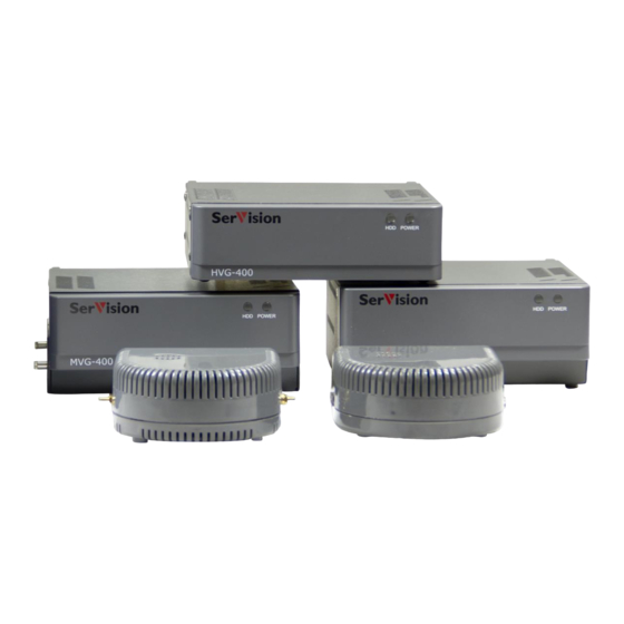
The following embedded Video Gateway models are currently available: HVG400: A four-channel Video Gateway optimized for homes and small offices. The HVG400 features a built-in hard drive capable of storing large quantities of recorded video and supports a cable-based connection to a network. -
Page 7: About Client Software
(http://www.servision.net). SerVision also offers client software for certain cellular telephones, tablet PCs, and PDAs. These applications, and user guides for them, can be downloaded from the SerVision website. In addition, SVControlCenter is a complete control-center solution that includes powerful client features, for enterprises managing sizable numbers of Video Gateways. -
Page 8: Installing Svmulticlient
To install the SVMultiClient application on the PC: 1. Download the latest version of the SVMultiClient installation program from the SerVision website (http://www.servision.net). The installation file is called Setup-MultiClient-SV-x.x.x.x.exe (The software version number appears in place of “... -
Page 9: Opening The Configuration Utility
2. In SVMultiClient, at the bottom of the , click the Search button. Connection panel Search Figure 3: Search button Find Gateway dialog box opens, and displays a list of all the SerVision systems connected to the network. Getting Started... - Page 10 SerVision Embedded Video Gateway System Guide Figure 4: Find Gateway dialog box Note: It may take a few minutes before the Video Gateway unit appears in the list. 3. Select the Video Gateway and then click Configure. A browser window opens and displays the configuration Login screen.
-
Page 11: Overview Of The Interface
SerVision Embedded Video Gateway System Guide Figure 6: Summary screen Overview of the Interface Main Menu The configuration utility consists of screens that are displayed on the right side of the window and a a sidebar on the left side of the window. -
Page 12: Status Bar
Login screen again Help button; click to open the SerVision website in a browser window. The website includes information about configuring and working with your Video Gateway system, including the most up-to-date version of this Support->Documentation->Manuals and Product Overviews... - Page 13 SerVision Embedded Video Gateway System Guide To configure a Video Gateway unit: Main Menu Cameras Sensors 1. In the , click one of the top-level options, e.g., . The selected summary screen opens. Main Menu 2. Click an option in the or a link in the summary screen to open the desired lower-level screen.
- Page 14 SerVision Embedded Video Gateway System Guide Note: If the update confirmation message does not appear, or an error message appears, all changes made since the last successful update of the page are discarded. 4. To modify additional settings, navigate to the relevant screen and make the changes as necessary. Click Update in each screen when you are finished modifying its settings.
-
Page 15: Opening The Configuration Remotely
Opening the Configuration Manually, below. Note: If more than one SerVision Video Gateway is connected to the internet via the same router, each of them must use a different port. When you click Config in SVMultiClient, the browser automatically connects to port 10000. - Page 16 SerVision Embedded Video Gateway System Guide To open the configuration utility manually, you must know the network address (IP or hostname) of the Video Gateway and the port allowing access to the configuration utility. The required network address depends on whether...
-
Page 17: Configuring System Settings
SerVision Embedded Video Gateway System Guide Configuring System Settings System settings include system-wide settings, such as the name of the unit, date and time settings, and network configuration. System Summary screen summarizes the current system settings and provides links to some of the system configuration screens in which the system settings can be modified. -
Page 18: General System Settings
SerVision Embedded Video Gateway System Guide SMS & E-mail: Event notification settings (see page 61) AVV: Configuration of automatic uploading of video to an FTP server (see page 67) FTP: Configuration of manual uploading of video to an FTP server (see page 74) ... - Page 19 SerVision Embedded Video Gateway System Guide System port, which is intended for client connections, and can be configured. The default number of this port appears on the sticker on the underside of the unit. (It is usually 9988.) You can configure this port as necessary to suit the requirements of your network.
- Page 20 Video Authentication: Adds a digital signature to each frame of video captured by the system. This signature makes it possible to identify frames that have been tampered with. When a SerVision client application plays video that has a digital signature and discovers a frame that has been changed from its original state, the status of the stream indicates that the stream was modified.
- Page 21 SerVision Embedded Video Gateway System Guide Real Time Bitrate Control: Tells the Video Gateway to monitor the video transmission, identify situations in which packets are not being transmitted quickly enough because of bandwidth limitations, and automatically modify the bitrate of the video to suit the available bandwidth. Activating this option enhances the stability and quality of the stream when bandwidth is limited, such as when the Video Gateway transmits video streams over a cellular connection.
-
Page 22: Configuring General System Settings
SerVision Embedded Video Gateway System Guide Configuring General System Settings To adjust the general system settings: Main Menu General System Settings 1. In the , under System, click General. The screen opens: Figure 16: General System Settings screen (MVG) 2. - Page 23 SerVision Embedded Video Gateway System Guide Field Description Note: If you want to access the unit remotely and cannot set up port forwarding for port 10000 in your network, you can also access the configuration utility using this port.
- Page 24 SerVision Embedded Video Gateway System Guide Field Description Disable TV-Out while Select this option to stop streaming to the CCTV monitor connected to the Video Downloading Gateway while downloading of recorded video to a PC is taking place.
- Page 25 SerVision Embedded Video Gateway System Guide Field Description IA Sensors Used If sensors are connected to the unit through an IA relay board, select the number of sensors that are connected to the board. For additional information, please refer to the unit’s installation guide.
-
Page 26: Configuring A Cctv Monitor (Tv-Out)
SerVision Embedded Video Gateway System Guide Configuring a CCTV Monitor (TV-Out) If a video monitor is connected to your Video Gateway, you must activate and configure it before you can see video on it. The monitor can be used for one of two purposes: to view video from the Video Gateway, or to play prerecorded video content that is stored on the unit, such as movies or ads. -
Page 27: Configuring The Monitor To Display Video From The Video Gateway
SerVision Embedded Video Gateway System Guide Figure 18: TV-Out settings displayed (MVG) Note: TV-Out cannot be enabled if recording framerates are very high (see Advanced Recorder Settings, page 106). In this case, if you attempt to enable TV-Out, a TV-Out Disabled message will be displayed: Figure 19: TV-Out Disabled message 3. - Page 28 SerVision Embedded Video Gateway System Guide NOTE: For information about viewing video from the Video Gateway unit on a connected CCTV monitor, see Appendix A: Viewing Video on a CCTV Monitor (TV-Out), page 207. To configure the CCTV monitor to display video from the Video Gateway: ...
- Page 29 Select this option if a switch is connected to the relevant sensor connector on the Sensor unit (In6 on the HVG400; In4 on the MVG400, and UVG400; In1 on MVG200, CVG, and CVG-M models), and you want to use the switch to cycle through the various display types.
- Page 30 SerVision Embedded Video Gateway System Guide Field Description Display Recording Select this option if you want the recording status to be displayed at the bottom of Status the screen at all times. The recording status indicates whether recording is taking...
-
Page 31: Configuring The Monitor To Play Prerecorded Video
Only video in the Video Gateway's standard format, SMF, can be played. If you want to use a CCTV monitor for this purpose, SerVision can provide you with a video-converter that you can use to convert your video files to the required format. - Page 32 When this occurs, playing of video in the CCTV monitor is temporarily suspended. It resumes automatically when the resources are once again available. NOTE: For additional information about this option, please contact SerVision technical support. To configure the CCTV monitor to play video from the Video Gateway: ...
-
Page 33: Settings Screen
SerVision Embedded Video Gateway System Guide Figure 25: Warning message NOTE: TV-Out When Content mode is enabled, this warning message appears every time you open the Settings screen. 4. In the message, click OK. 5. Open the Save Settings page. A warning message appears in the page, informing you that all existing recording on the unit will be erased when you save the settings. -
Page 34: Setting The Unit Time
SerVision Embedded Video Gateway System Guide Save Settings 7. In the screen, click Save Changes to System. The unit stores the changes permanently, all System Restart Page recorded video on the unit is erased, and the screen opens: 8. Click Restart System. The unit restarts, and the changes are implemented. - Page 35 SerVision Embedded Video Gateway System Guide 2. Under DST Control Type, select one of the following options: Option Description Manual Lets you activate and deactivate daylight savings time manually. When this option is selected, the Enabled checkbox appears below the DST Control Type field. Select this checkbox when daylight savings time begins, and clear it when daylight savings time ends.
-
Page 36: Updating The Date And Time Manually
SerVision Embedded Video Gateway System Guide Updating the Date and Time Manually You should set the unit date and time manually when you first set up the system and when the Video Gateway has not been used for a while. If you cannot or do not want to implement automatic time setting, you should also update the time manually whenever the date and time are no longer accurate. - Page 37 SerVision Embedded Video Gateway System Guide Sync Time confirmation message Figure 31: System Restart Page after manual time updating In two cases, the screen that is displayed may differ from the one in figure 31: if there were unsaved updates when the time was synchronized, and if the clock was set ahead more than about 15 minutes.
-
Page 38: Configuring Automatic Time Setting
SerVision Embedded Video Gateway System Guide Message Figure 33: System Restart Page if the time was synchronized when there were unsaved changes To save unsaved changes after the time was synchronized: Save Settings 1. Click the message. The page opens. -
Page 39: Lan Settings
SerVision Embedded Video Gateway System Guide attempts to connect, it begins with the first server listed. If it fails to connect to that server, it tries the next on the list, and so on. If you wish, you can replace any or all of the time servers on the list with other time servers, or add additional time servers, to a maximum of ten servers. - Page 40 2. For the MVG400 and UVG400, under Router, select Enable. For the CVG and CVG-M, if the unit is connected to an external SerVision router, under Router, select Enable. Do not select this option if the unit is connected to any other type of router.
-
Page 41: Modem
Modem support in models that use SerVision routers (MVG400, MVG200, and UVG) is slightly different from modem support in the CVG-M, which has a built-in modem GSM and therefore does not need a router. -
Page 42: Video Gateway With Router
SerVision Embedded Video Gateway System Guide Video Gateway with Router Modem settings configure the system to use the cellular modem connected to the unit’s USB port. Before you configure the modem, ask your cellular supplier for the correct settings. When the modem is correctly configured, the Video Gateway automatically attempts to establish a connection to the cellular network through it. - Page 43 SerVision Embedded Video Gateway System Guide NOTE: Unless you have made other changes to the configuration that require a system restart, it is not necessary to restart the system after the modem settings are saved on MVG and UVG400 units.
- Page 44 SerVision Embedded Video Gateway System Guide Figure 39: Modem Enabled (CDMA settings) 4. If you selected GSM, fill in the fields as follows: Field Description Username If the cellular supplier requires a username, fill in the username. Password If the cellular supplier requires a password, fill in the password.
- Page 45 7. Clear the Debug Mode checkbox unless you are instructed by SerVision technical support staff to select it. 8. If the connection to the cellular network is frequently lost or the quality of the connection is often low, select Verify to configure the unit to test the cellular network connection periodically.
-
Page 46: Cvg-M
SerVision Embedded Video Gateway System Guide CVG-M The CVG-M has a built-in cellular GSM modem. The modem settings configure the CVG-M to connect to a cellular network; the settings are implemented if a SIM card is installed in the unit. Before you configure the modem, ask your cellular supplier for the correct settings for the SIM card you are planning to use. - Page 47 SerVision Embedded Video Gateway System Guide Figure 42: Modem enabled 3. Fill in the fields as follows: Field Description Username If the cellular supplier requires a username, fill in the username. Password If the cellular supplier requires a password, fill in the password.
-
Page 48: Wifi
SerVision Embedded Video Gateway System Guide WiFi WiFi settings can configure the system to connect to external access points (hotspots) or to function as an access point for external devices. NOTE: When the unit is configured to function as an access point, it cannot also connect via WiFi to other, external access points. -
Page 49: Wifi Connection
SerVision Embedded Video Gateway System Guide SSID of WiFi Additional IP in the WiFi WiFi connection status network network status information Figure 43: System Summary screen showing WiFi connected to access point In order to connect to an access point, you must supply its service set identifier (SSID), which is essentially the name of the wireless network. - Page 50 SerVision Embedded Video Gateway System Guide NOTE: Unless you have made other changes to the configuration that require a system restart, it is not necessary to restart the system after these WiFi settings are saved. To configure the unit to connect to an access point: ...
- Page 51 SerVision Embedded Video Gateway System Guide Figure 45: SSIDs in Range 6. If the access point requires an encryption key, specify the following: Under Security, select the encryption method used by the access point (WEP or WPA). Under Key, fill in the encryption key.
- Page 52 SerVision Embedded Video Gateway System Guide Field Description Fill in the IP address of the DNS server used by the access point. A DNS server enables you to enter names instead of IP addresses for the proxy and DDNS servers.
-
Page 53: Removing An Access Point From The List
SerVision Embedded Video Gateway System Guide Figure 48: Video Gateway connected to "SV-WIFI" access point If Random Selection of SSID is enabled, the unit remains connected to that access point until the connection is lost. If Random Selection of SSID is cleared, it disconnects from the access point if it can connect to a higher-priority access point. -
Page 54: Configuring The Unit To Function As An Access Point
SerVision Embedded Video Gateway System Guide NOTE: When WiFi is turned off, all SSIDs in the Configured SSIDs list have the status "Not in Range," and System Summary the list of access points that are within range does not appear. In the screen, and in the statistics window of the SVMultiClient, the WiFi network status appears as "Connected, Disabled."... -
Page 55: Network Priorities
SerVision Embedded Video Gateway System Guide Figure 50: Access-point configuration settings 2. Fill in the fields as follows: Field Description AP SSID Enter the SSID of the unit's WiFi network (i.e., the name of the access point; see page 48) AP Authentication Type Select the type of encryption to use (WEP, WPA, WPA2). -
Page 56: Port Forwarding
SerVision Embedded Video Gateway System Guide To prioritize the network connections: Main Menu Network Priorities 1. In the , under System, click Network Priorities. The screen opens, and displays the three networks – LAN, WLAN (WiFi), and Cell (Modem) – in their current order of priority (the top network is ranked highest). - Page 57 NOTE: Be sure to assign a static internal IP to the device before you set up port forwarding to it (see Appendix C: Networks Managed by SerVision Routers, page 238) To configure port forwarding for a device connected to the unit's router: ...
-
Page 58: Proxy And Ddns Settings
IP address. The DDNS service ensures that the correct public IP address is linked to the name at all times, even when the IP changes. Three DDNS services are supported by the system: SV-DDNS (SerVision's DDNS service), No-IP, and DynDNS. For information about the SV-DDNS service, consult your vendor. For information about the No-IP and DynDNS DDNS services, consult their websites (www.no-ip.com... - Page 59 Modem: The unit will only use a Modem connection. If none is available, the unit will not connect to the proxy server. HVG400, CVG, CVG-M: Not currently in use. Host/IP Fill in the IP address or hostname of the proxy server.
- Page 60 For example, you can include your name or the name of your company in the hostname to ensure it is unique. The complete hostname on the SerVision SV-DDNS server will be composed of the name you type plus .
-
Page 61: Authentication
Under Confirm Password, type the password a second time to ensure you typed it correctly. Note: SerVision cannot provide support for problems related to the No-IP or DynDNS DDNS services. For technical support, please contact the service providers. -
Page 62: Sms And E-Mail Notifications
SerVision Embedded Video Gateway System Guide A user with all client permissions – live video, recorded video, and camera control – but no configuration permission. The default username for this user is anonymous and the password is guest. You can modify the default settings and add new users as necessary. It is recommended that you change the default usernames and passwords of both of the default users. - Page 63 SerVision Embedded Video Gateway System Guide Figure 60: E-mail event notification If you opt to write-protect recorded video (see Advanced Recorder Settings, page 106), you can also choose to send an e-mail warning message when the disk space allocated to a recorder is almost full or is entirely full.
- Page 64 SerVision Embedded Video Gateway System Guide To configure SMS and e-mail notification settings: Main Menu SMS and E-mail 1. In the , under System, click SMS & E-mail. The screen opens: Figure 62: SMS and E-mail screen 2.
- Page 65 SerVision Embedded Video Gateway System Guide Field Description Name The name of the person who will receive an SMS or e-mail message when an event occurs (up to 20 characters). E-mail / Fill in the phone number or e-mail address of the recipient.
- Page 66 Fill in the Sender ID that was assigned by Clickatell. Note: If you do not have an active Clickatell account, open one at http://www.clickatell.com. Note: SerVision cannot provide support for problems related to the Clickatell service. For technical support, please contact Clickatell.
-
Page 67: Sms Message Templates
SerVision Embedded Video Gateway System Guide Field Description sender User Name Enter the user name to insert in the address of the e-mail message. For example, if you want the sender address to be alert@test.com, enter alert SMTP If the SMTP server requires authentication, select Enabled. -
Page 68: Testing Notification Settings
SerVision Embedded Video Gateway System Guide Sensor (Front Door) ON activated on Bus-5478 at 22 Feb 07 00:17:16 The recipient name is set in each message to match the name of the recipient as it appears in the Recipient list below the message template. - Page 69 SerVision Embedded Video Gateway System Guide Figure 67: AVV notification e-mail – start of upload Figure 68: AVV notification e-mail – upload completed On the MVG and UVG400, video files are sent by the Video Gateway using the highest-priority network connection available.
- Page 70 SerVision Embedded Video Gateway System Guide Configuring Video Lost, page 102 Configuring Sensor and Activator Settings, page 119 NOTE: A list of devices that are configured to trigger AVV is displayed at the top of the AVV screen (see figure 72, page 71).
- Page 71 SerVision Embedded Video Gateway System Guide Field Description Use Same Server for If the URL for uploading and downloading is the same, select this checkbox. Upload and Download Otherwise, clear this checkbox. The Download Server field is added to the screen.
- Page 72 SerVision Embedded Video Gateway System Guide Field Description Note: Large frame (VGA or D1) is available only if large-frame recording is activated for Advanced Recorder one or more of the cameras connected to the Video Gateway. (See Settings , page 106.)
-
Page 73: Viewing The List Of Files On The Avv Server
SerVision Embedded Video Gateway System Guide Viewing the List of Files on the AVV Server You can view a list of the files on the AVV server by navigating to the http directory on the server. The name of each file indicates the device that detected the event, and the date and start-time of the event. For example: Office_Security_VMD_(Back_Door)(2)_09_07_2007_20_43_51.svr... - Page 74 SerVision Embedded Video Gateway System Guide link Figure 75: E-mail notification with video link Otherwise, navigate to the download site though the browser as described above, and click the required file in the list. If the site requires authentication, a dialog box opens, requesting the username and password.
-
Page 75: Disabling Avv
SerVision Embedded Video Gateway System Guide 4. Navigate to the location on your PC in which you want to save the video clip file, and then click Save. The file is saved in the selected location. 5. Open SVMultiClient. 6. Play the video clip file in SVMultiClient in one of the following ways: ... - Page 76 SerVision Embedded Video Gateway System Guide Configuring Video Lost, page 102 Configuring Sensor and Activator Settings, page 119 To configure the settings of the FTP server: Main Menu FTP Download 1. In the , under System, click FTP. The...
-
Page 77: Schedules
SerVision Embedded Video Gateway System Guide Field Description Username Fill in the username required to access the FTP directory on the FTP server. Password Fill in the password required to access the FTP directory on the FTP server. - Page 78 SerVision Embedded Video Gateway System Guide Figure 78: Schedules screen (inactive) 2. Select Enabled. The schedule grid and its controls are displayed. Schedule grid Outline- attachment controls User-defined holidays (if any) Figure 79: Schedules enabled The upper part of the screen contains the schedule grid. Below it are controls that allow you to attach specific outlines to particular days and times in the grid.
-
Page 79: Configuring A Standard Weekly Schedule
SerVision Embedded Video Gateway System Guide Cell representing one hour Key to color- coding Figure 80: Color-coded schedule 3. Follow the instructions below to create a basic, repeating weekly schedule and to add holidays to the schedule. Configuring a Standard Weekly Schedule This section explains how to set up a basic, repeating weekly schedule of outline implementation. - Page 80 SerVision Embedded Video Gateway System Guide Selected outline Figure 81: Color-coded schedule 2. If you want to apply the outline to the entire week’s schedule, click Set all schedules to currently selected outline. All of the rectangles in the schedule grid are switched to the color representing the selected outline.
-
Page 81: Defining Holiday Schedules
SerVision Embedded Video Gateway System Guide Click the diagonally opposite corner of the rectangular area that you want to mark. The selected outline is applied to the entire rectangle. Figure 83: Clicking the diagonally opposite corner of the area Note: The entire schedule grid, representing full 24-hour days, may not be visible at one time on your screen. - Page 82 SerVision Embedded Video Gateway System Guide Edit Holidays Figure 84: Edit Holidays Holidays screen opens. The screen displays the schedule grid at the top (it is not editable here), and below it, a list of the holidays that are already defined (if any).
- Page 83 SerVision Embedded Video Gateway System Guide Figure 85: Holidays screen New Holiday 2. Click Add Holiday. A blank section opens. Figure 86: New Holiday section 3. Fill in the fields as follows: Field Description New Years Day Name The name of the holiday, e.g.,...
-
Page 84: Defining A New Schedule Row
SerVision Embedded Video Gateway System Guide Field Description Repeating If the holiday occurs every year on the same date(s), select this checkbox. If the holiday occurs on different dates every year, or is only taking place once, clear this checkbox. - Page 85 SerVision Embedded Video Gateway System Guide New row Add Row button Figure 88: New row in schedule grid 2. In the text field, modify "New Schedule" to define a name for the schedule. Name Figure 89: Naming a new row 3.
-
Page 86: Audio Settings
SerVision Embedded Video Gateway System Guide 4. Follow the instructions under Configuring a Standard Weekly Schedule, page 78 to select the outlines to implement in each time slot. Holidays Note: To assign the new schedule to a holiday, click Edit Holidays to open the screen. -
Page 87: Configuring Microphone And Speaker Volume
Configuring a CCTV Monitor (TV-Out) , page 25. Note: On the HVG400, even if the internal speaker is enabled here, it can still be turned off by flipping down the Mute switch on the rear of the unit. Internal Speaker Set the output volume for the unit’s built-in speaker, as explained under... - Page 88 Audio Settings 2. In the screen, under Audio In, select a volume setting for the microphone. (For HVG400, MVG400, and UVG400 models, which have two microphone connectors, “CH1” sets the volume of the microphone connected to Ain1, and “CH2” sets the volume for Ain2).
-
Page 89: Configuring Gps
– to display in a map, monitor vehicle locations and possible deviations from the intended route – or store the data for future use. NOTE: SerVision does not provide any software for handling NMEA data that is transmitted to an NMEA server. You must acquire and set up any required software on your own. Configuring System Settings... - Page 90 SerVision Embedded Video Gateway System Guide To configure the GPS settings: GPS Settings 1. In the screen, under GPS, select Enabled. The fields required to configure the GPS settings are added to the screen: Figure 95: GPS settings 2.
-
Page 91: Erasing Recorded Gps Data
SerVision Embedded Video Gateway System Guide Field Description RMC to serial Select this option if you want to send GPS data in RMC syntax to a device connected to the serial port of the Video Gateway unit. The data is sent at 4800 baud, 8 bits, no parity, one stop bit (8N1). -
Page 92: Configuring Camera Settings
SerVision Embedded Video Gateway System Guide Configuring Camera Settings Camera screens are used to configure the cameras connected to the Video Gateway unit. Settings include the name of the camera; the desired brightness, contrast, and saturation; pan-tilt-zoom (PTZ) settings; audio settings;... - Page 93 SerVision Embedded Video Gateway System Guide NOTE: For information about the Erase Recordings and Set Recording Disk Size to Default options, see Erasing Recorded Video, page 113. For information about the Restore Recording Settings to Default option, see Restoring Default Recording Settings, page 110.
- Page 94 SerVision Embedded Video Gateway System Guide Figure 100: Camera enabled Note: If Enabled is not selected, the camera cannot record and will not appear in client applications. 3. Fill in the fields as follows: Field Description Description Type a name for the camera (up to 20 characters). Each of the cameras must have a different name.
- Page 95 (HVG400, MVG, and UVG400 only). Note: In HVG400 units that only support one microphone, you will either see Channel 1 or Channel 2 in the dropdown list, depending on which one was activated. For additional information, see the description of the Input Volume field (page 86).
-
Page 96: Configuring Ptz
SerVision Embedded Video Gateway System Guide 7. If you do not want audio to be incorporated with the video recorded from the camera, under Audio Recording, clear the Enabled checkbox. Note: The Audio Quality field is not currently in use. All audio recordings have medium quality. -
Page 97: Video Motion Detection (Vmd)
SerVision Embedded Video Gateway System Guide Field Description Baud Rate Select the baud rate used by the camera for PTZ control. Note: Consult the camera documentation or the camera vendor for this information. Note: The other connection parameters required by the Video Gateway are:... -
Page 98: About Responses To Vmd Events
SerVision Embedded Video Gateway System Guide To solve these two problems, VMD event detection can be configured to control the length of events using the following parameters: Debounce: The interval between the end of motion as detected by the unit and the time when the event is defined as ending ... - Page 99 SerVision Embedded Video Gateway System Guide Figure 104: VMD settings 2. If you want to define the level of sensitivity of the motion detection that is implemented in the field of view (FOV), and perhaps specify different levels of sensitivity for different regions of the FOV, under Regions, select Enabled.
- Page 100 SerVision Embedded Video Gateway System Guide Mark Description Blue Low VMD sensitivity Green Medium VMD sensitivity High VMD sensitivity None No motion detection Black x on white background Region blacked: no video capture 4. If you want to set the entire FOV to the specified sensitivity level, click the relevant sensitivity level, and then click Set all regions.
- Page 101 SerVision Embedded Video Gateway System Guide Figure 107: Sensitivity level applied to selected rectangle 6. If you want to apply the current sensitivity level to individual regions, do one of the following: With the Change Multiple Times checkbox selected, double-click the region.
- Page 102 SerVision Embedded Video Gateway System Guide 9. Under Maximum Event Length, specify the maximum length of a VMD event, in seconds. Range: 60–86400 seconds (1 minute – 1 day). If motion is detected continuously for longer than this period of time, a new event is automatically generated at the end of this interval.
-
Page 103: Configuring Video Lost
Note: For additional information about working with activators, see and Activator Settings, page 119. Note: The Activator 2 field only appears for the HVG400, MVG, and UVG400. Go To Preset All PTZ cameras connected to the Video Gateway that support presets are listed below this heading. - Page 104 SerVision Embedded Video Gateway System Guide Figure 109: Video Lost settings Field Description Select this option to have the Video Gateway send video of the seconds preceding the video-lost event to an AVV server for downloading. The video is downloaded to the site...
-
Page 105: Video Recording Settings
Note: For additional information about working with activators, see and Activator Settings, page 119. Note: The Activator 2 field only appears for the HVG400, MVG, and UVG400. Go To Preset All PTZ cameras connected to the Video Gateway are listed below this heading. If you want one of these cameras to automatically aim at a preset location when a video-lost event begins, beside the name of the camera, select the number of the preset location. -
Page 106: Configuring Video Recording
SerVision Embedded Video Gateway System Guide each second of recording. Obviously, some stream quality is lost when lower quality settings are used. All three standard quality settings produce recordings in SIF size when the unit’s video resolution is VGA and recordings in CIF size when the video resolution is D1 (see Video Resolution, page 18). -
Page 107: Advanced Recorder Settings
SerVision Embedded Video Gateway System Guide Sensor events: If you want sensor events to trigger event recording, select the sensors you want to function as triggers. For example, select S1 to use Sensor 1 as a trigger. - Page 108 SerVision Embedded Video Gateway System Guide Resolution Frame Size High Quality Medium Low Quality Quality 7 FPS 5 FPS 4 FPS (large frame) 320 KBPS 256 KBPS 128 KBPS 3.3 GB/day 2.64 GB/day 1.3 GB/day Table 1: Recommended video quality settings NOTE: Bitrate is defined in kilobits per second (KBPS), and framerate is defined in frames per second (FPS).
- Page 109 SerVision Embedded Video Gateway System Guide (WP) Figure 111: (WP) indicating linear recording (Write Protection) is selected CAUTION: When you update a recorder's disk allocation or size settings, all the recorded video that is currently stored on the storage media is deleted.
- Page 110 SerVision Embedded Video Gateway System Guide The percentage that is already allocated for the other cameras is indicated above the field – for example, “33% in use by other recorders.” You can choose to allocate as much of the remaining disk space to this recorder as you wish.
-
Page 111: Restoring Default Recording Settings
SerVision Embedded Video Gateway System Guide Field Description Framerate Enter the desired number of frames per second. Note: The note in parentheses above the field shows the global system framerate – the maximum number of frames the unit can process per second (from all cameras), and the maximum framerate available for this camera given the framerates that are already allocated to the other cameras in the system. - Page 112 SerVision Embedded Video Gateway System Guide Restore default recording settings Figure 114: Restoring default recording settings You are prompted to confirm that you want to erase all the recordings and restore the disk allocation: Figure 115: Confirm restoration prompt Note: This prompt appears even if no recorded video exists.
- Page 113 SerVision Embedded Video Gateway System Guide Save Settings 3. Click Click here to go to Save Settings page. The page opens. If any of the cameras were previously configured to record full-screen VGA or D1 frames, or quarter-sized QSIF or QCIF frames, a warning message is displayed.
-
Page 114: Erasing Recorded Video
SerVision Embedded Video Gateway System Guide Erasing Recorded Video Recorded video is normally stored on the storage media until one of the following occurs: The video is over-written by newer video. You change the recording size or disk allocation settings of one of the cameras (see Advanced Recorder Settings, page 106). -
Page 115: Erasing All Recorded Video From The Storage Media
SerVision Embedded Video Gateway System Guide Figure 120: Confirmation prompt Main Menu 3. Click OK. The recordings are erased, and a confirmation message appears below the Figure 121: Confirmation that recordings were erased 4. Restart the unit. Note: No recording will take place from the camera until the unit is restarted (see Resetting the Unit, page 197). - Page 116 SerVision Embedded Video Gateway System Guide Figure 122: Erase Recordings System 2. Select Confirm Erase, and then click Erase. The contents of the storage media are erased, and a Restart screen is displayed. Figure 123: System Restart screen after recordings are erased 3.
-
Page 117: Restoring The Default Disk Allocation
SerVision Embedded Video Gateway System Guide Figure 124: Restart confirmation message Note: To continue configuring the unit, click the link in the message and log into the configuration utility again. Restoring the Default Disk Allocation This section explains how to erase all recorded video from the unit’s storage media and, at the same time, restore the disk space allocation to its default settings. - Page 118 SerVision Embedded Video Gateway System Guide Figure 126: Confirm disk reallocation prompt Main Menu 2. Click OK. An Update Confirmation (ATTENTION) message appears below the Figure 127: Update Confirmation message 3. Click “Click here to go to Save Settings page.” The...
- Page 119 SerVision Embedded Video Gateway System Guide Figure 129: System Restart Page screen Note: From the time you click Save Changes to System, the existing video recordings become inaccessible. No additional recording can take place until the unit is restarted. 5. Click Restart System. The existing video recordings are erased, and the unit restarts. After the unit restarts, recording begins again.
-
Page 120: Configuring Sensor And Activator Settings
MVG 400 and UVG400 models, and up to six sensors and two activators can be connected directly to the HVG400. Up to 16 additional sensors can be connected to Video Gateway units through an ADAM module. Alternatively, additional sensors and activators can also be connected using an IA relay board, but they cannot be configured through the Video Gateway’s configuration utility. - Page 121 SerVision Embedded Video Gateway System Guide Figure 130: Sensor Summary screen (MVG400) Each sensor and activator in the system is configured in its own configuration screen. The configuration screens are Sensor Summary accessed from the screen. Sensors connected to the unit through an ADAM module appear as “External Sensors.”...
- Page 122 SerVision Embedded Video Gateway System Guide Figure 131: Sensor configuration screen 2. Select the Enabled checkbox. The fields required to configure the sensor or activator settings are added to the screen. Figure 132: Sensor enabled Configuring Sensor and Activator Settings...
- Page 123 SerVision Embedded Video Gateway System Guide Figure 133: Activator enabled Note: If Enabled is not selected, the sensor cannot function as an event trigger and will not appear in client applications. Sensor Note: If a sensor is not physically connected to the Video Gateway but is enabled in the screen, false alarms may be generated.
- Page 124 SerVision Embedded Video Gateway System Guide Field Description from “on to off” (normally closed) when an event occurs. Consult the device’s manual to determine its normal state. Note: This field is equivalent to the "Polarity" field for sensors.
- Page 125 None: Do not change the activator’s status. Note: These settings are not available for activators. Note: The Activator 2 field only appears for the HVG400, MVG, and UVG400. Load Outline If Sensor 1 is a toggle switch that will be used to switch outlines, select...
-
Page 126: Configuring Sensor 1 To Switch Outlines
SerVision Embedded Video Gateway System Guide 5. Under Notifications, under When Sensor Off or On Activator Deactivated, specify the actions that should be performed when an event ends, as described above. 6. Click Update, and then save the settings. They will be implemented after the unit is restarted (see Saving Configuration Changes, page 156). -
Page 127: Configuring A Sensor To Control Cctv Display
Camera 2: Full-screen display of live video from Camera 2 Camera 3: Full-screen display of live video from Camera 3 (HVG400, MVG, UVG400 only) Camera 4: Full-screen display of live video from Camera 4(HVG400, MVG, UVG400 only) ... -
Page 128: Configuring An Activator As A Power Switch
SerVision Embedded Video Gateway System Guide To configure a sensor as a CCTV display switch: Main Menu Sensor 1. In the , under Sensors, click the appropriate sensor (see above). The configuration screen opens. 2. Select the Enabled checkbox. The fields required to configure the sensor settings are added to the screen. -
Page 129: Configuring Vehicle-Behavior Sensors
SerVision Embedded Video Gateway System Guide Figure 138: Activator #1 configured as a power switch (MVG400) 4. Click Update, and then save the settings. They will be implemented after the unit is restarted (see Saving Configuration Changes, page 156). Configuring Vehicle-Behavior Sensors... - Page 130 SerVision Embedded Video Gateway System Guide To create the GPX file in Bing, you mark routes and/or areas on the map. The Bing system stores the GPS coordinates of the routes and areas as places in your My Places. When you have marked all of the routes and areas that define the intended range of the vehicle, you can export the information and save it in a GPX file.
- Page 131 SerVision Embedded Video Gateway System Guide To create a GPX file using Bing maps: 1. In a browser, open the Bing maps site (http://www.bing.com/maps/) and display the part of the map that represents the region in which the vehicle will be travelling. Zoom in so that you can see the features you want to mark on the map (e.g., roads and towns).
- Page 132 SerVision Embedded Video Gateway System Guide Figure 144: Drawing a route Figure 145: Drawing an area Edit 5. When you get to the last point you want to include in the area or route, double-click the point. An pushpin properties dialog box opens.
- Page 133 SerVision Embedded Video Gateway System Guide Figure 146: Edit pushpin properties dialog box 6. Under Title, enter a name for the item, and then click Save. The item is saved in the Unsaved places list. Note: Do not include any spaces in the name.
- Page 134 SerVision Embedded Video Gateway System Guide Figure 148: Exporting items to a GPX file 9. Select Save File. A Windows Save File dialog box opens. 10. Navigate to the folder in which you want to save the file, modify the default name of the file if you wish, and then click Save.
- Page 135 SerVision Embedded Video Gateway System Guide Figure 149: Opening the Remote Route Selection utility in SVMultiClient Figure 150: Remote Route Selection utility To open the Remote Route Selection utility in SVControlCenter: 1. Make sure SVControlCenter is connected to the Video Gateway. (For additional information, please refer to the SVControlCenter User Guide.)
- Page 136 SerVision Embedded Video Gateway System Guide Figure 151: Opening the Remote Route Selection utility in SVControlCenter To upload routes and areas from a GPX file to a Video Gateway: 1. On the right side of the utility, click Load GPX file. A Windows File Selector dialog box opens.
- Page 137 SerVision Embedded Video Gateway System Guide Figure 153: Confirmation message 6. Click OK. The message closes. 7. Repeat steps 4-5 for each of the polygons you want to upload to the Video Gateway. Note: Each polygon is uploaded to a separate file. To see a list of the geo-fencing files that are currently stored on the Video Gateway, in the upper left of the window, click Query files on unit.
- Page 138 SerVision Embedded Video Gateway System Guide Figure 155: Creating an itinerary 3. Click Add. The itinerary is saved on the Video Gateway, and a confirmation message appears. Figure 156: Confirmation message Note: To see the itinerary in the list of geo-fencing files that are on the Video Gateway, in the upper left of the window, click Query files on unit.
- Page 139 SerVision Embedded Video Gateway System Guide Figure 157: List of geo-fence files on the Video Gateway 2. Click OK. The dialog box closes. 3. In the Files dropdown list, select the item you want to activate. Figure 158: List of geo-fencing files displayed Note: In the list, the names of the fences and routes are followed by their type (either “fence”...
- Page 140 SerVision Embedded Video Gateway System Guide Figure 159: Activation confirmation message Note: Geo-fence events will only be triggered if the Video Gateway's geo-fence sensor is enabled and configured (see Configuring the Geo-Fence Sensor Settings, page 139). Defining a Perimeter Limit Instead of defining the geo-fence boundaries by defining polygons using a GPX file, you can define geo-fencing boundaries by specifying a radius from the current location of the vehicle.
- Page 141 SerVision Embedded Video Gateway System Guide NOTE: You can configure these settings before you activate the geo-fence boundaries. If no boundaries are active, no events will be generated, but the settings will be saved in the system and applied when you...
- Page 142 SerVision Embedded Video Gateway System Guide Black: The geo-fence sensor is disabled. Blue: Fence mode is active. Red: Perimeter mode is active. The state of the sensor is indicated by the icon of the GF/Perim sensor, as explained below.
- Page 143 SerVision Embedded Video Gateway System Guide Location icon Figure 163: Blue location icon indicating Fence mode is active Mode and State Indicators in SVControlCenter In SVControlCenter, the current mode and state are indicated as follows: In the left panel, the icon of the GPS sensor indicates the current mode:...
- Page 144 SerVision Embedded Video Gateway System Guide In the left panel, the icon of the GF/Perim sensor indicates the current state: indicates the sensor is on (i.e., the vehicle is outside the fence area) and indicates the sensor is off (i.e., the vehicle is within the fence area).
- Page 145 SerVision Embedded Video Gateway System Guide Switch Off All Advanced Features: Disable geo-fencing Switch to Geo Fence Mode: Activate Fence mode with the boundaries defined in the active fence file Remote Switch to Perimeter Mode: Activate perimeter mode with the radius that was last defined in the...
-
Page 146: Configuring A Speed-Limit Sensor
SerVision Embedded Video Gateway System Guide 2. Select Cancel GEOF/PERIM. The geo-fence sensor is disabled, and a confirmation message appears. 3. Click OK. The message closes. 4. Modify the settings as required. Note: Follow the instructions above to upload new polygon files (see p. 133), create a new itinerary (see p. -
Page 147: Configuring An Idle Monitor
SerVision Embedded Video Gateway System Guide 2. Select the Enabled checkbox. The fields required to configure the settings are added to the screen. Figure 171: Speed Limit Alert screen 3. Under Maximum Speed, select the highest speed the vehicle can go without triggering an event. If the vehicle goes faster than this speed, the sensor will trigger a speeding event. -
Page 148: Configuring A G-Force Sensor
SerVision Embedded Video Gateway System Guide Figure 172: Idle Monitoring screen 3. Under Maximum Idle Time, enter the longest amount of time the vehicle can remain in one place without triggering an event, in minutes. If the vehicle remains in any location longer than this amount of time, the sensor will trigger an event. - Page 149 SerVision Embedded Video Gateway System Guide they were detected less than 30-seconds apart, and 30 seconds without an event would have to pass in order for a new event to be identified. To configure a G-Force sensor: ...
-
Page 150: Defining Alternate Outlines
SerVision Embedded Video Gateway System Guide Defining Alternate Outlines Outlines define alternate sets of recording and event-handling settings. For example, for the MVG, you could define one set of settings for times when the vehicle is in operation and another set for when it is parked; when the vehicle is in operation, the motion and sensor notifications would be turned off, but when it is parked, they would be turned Outline configuration is an optional feature of the Video Gateway. - Page 151 SerVision Embedded Video Gateway System Guide Figure 175: Show Outlines screen Outlines 2. Click Show Outlines. The screen opens: Figure 176: Outlines screen Note: The Load Outline on System Start checkbox and the Activate button do not appear if sensor-triggered General or scheduled outline switching is activated.
- Page 152 SerVision Embedded Video Gateway System Guide Figure 177: Outline #1 summary screen 4. Select Enabled. The outline's initial recording and event-handling settings are displayed: Defining Alternate Outlines...
- Page 153 SerVision Embedded Video Gateway System Guide Figure 178: Outline #1 summary screen – enabled Note: The initial settings of each outline are based on the Default outline. 5. Under Outline Name, modify the name of the outline as required, and then click Update. The name is updated.
- Page 154 SerVision Embedded Video Gateway System Guide Click to open Outline 1, Camera 1 Settings Figure 179: Opening Outline 1, Camera 1 settings in the Main Menu The configuration screen for the device opens. Figure 180: Outline 1, Camera 1 configuration screen...
-
Page 155: Activating Outlines Manually
SerVision Embedded Video Gateway System Guide Note: If a device is not enabled in the Default outline, it cannot be enabled in any other outline. In this case, the configuration screen of the device in the outline section will say the device is disabled (see figure 181). For information about activating a device in the Default outline, see page 120. - Page 156 SerVision Embedded Video Gateway System Guide To manually switch the running outline: In the Outlines screen, in the line in which the outline is listed, or in the relevant outline configuration screen, Outlines click Activate. The selected outline runs immediately. If the screen was not already opened, it opens and displays an updated summary of the outline settings.
-
Page 157: Saving Configuration Changes
SerVision Embedded Video Gateway System Guide Saving Configuration Changes As you make changes in each screen, you click the Update button to save the changes. However, in order to complete the save operation and update the Video Gateway, you need to carry out the steps described below. Most configuration changes only take effect after you carry out all of these steps. - Page 158 System Restart Note: The page of MVG and UVG400 units, which have built-in SerVision routers, contains a Restart Router button. For information about this button, see Resetting the Unit, page 197. 3. Click Restart System. The unit restarts, and the changes are implemented. You are automatically logged out of the configuration utility, and a confirmation message appears.
-
Page 159: Discarding Changes
SerVision Embedded Video Gateway System Guide Figure 185: Restart confirmation message Note: To continue configuring the unit, wait at least 30 seconds, and then click the link and log into the configuration utility again. Note: If you do not restart the unit at this time, most changes are not implemented on the unit, but they are saved on it. -
Page 160: Restoring Default Settings
SerVision Embedded Video Gateway System Guide Figure 186: Changes Discarded screen 3. Continue configuring the unit as required. Restoring Default Settings If the unit does not function as expected, and you believe this is the result of recent configuration changes, you can choose to restore all of the original factory settings to the unit. - Page 161 SerVision Embedded Video Gateway System Guide Figure 187: Confirm Restore screen 3. Select Are you sure you want to restore factory defaults?. Note: If you do not select this option, the unit's settings will not be restored, even if you click Confirm.
- Page 162 SerVision Embedded Video Gateway System Guide Figure 188: System Restart Page after default settings are restored 6. Click Restart System. The unit restarts, and the factory default settings are implemented. You are automatically logged out of the configuration utility, and a confirmation message appears.
- Page 163 SerVision Embedded Video Gateway System Guide If the primary IP used by the unit before you restored the default settings was the default, factory- configured IP, click the link in the confirmation message to log into the configuration utility and reconfigure it.
-
Page 164: Connecting To The Video Gateway
Client applications: For full client features, such as video streaming, event monitoring, and PTZ camera control, you must use one of the SerVision client applications. Applications that run on PCs and on certain cellular telephone and PDA models are available. For additional information, see About Client Software, page 6, and refer to the SerVision website (www.servision.net). - Page 165 SerVision Embedded Video Gateway System Guide Figure 191: Find Gateway dialog box 3. Select the Video Gateway and then click Connect. SVMultiClient connects to the Video Gateway, and the Connection Panel Video Gateway appears in the Connection Panel 4. In the , expand the system to display all the devices connected to it.
-
Page 166: Connecting Through The Configuration Utility
SerVision Embedded Video Gateway System Guide Camera pane Camera in the Connection Panel Figure 193: Viewing area NOTE: The number of video streams (live and/or recorded) that the Video Gateway can supply simultaneously is limited. This limit is based on the system configuration and is due to memory constraints. -
Page 167: Viewing Events
SerVision Embedded Video Gateway System Guide Figure 194: Initial screen when logging in as a client user Viewing Events You can view lists of recorded events that are stored on the Video Gateway. To view lists of events: ... - Page 168 SerVision Embedded Video Gateway System Guide Figure 196: Lists of events Connecting to the Video Gateway...
-
Page 169: Viewing Snapshots
. This means you can see what is happening on-site wherever you are, as long as you have access to a computer that is connected to the internet – even if you do not have a client device with a SerVision client application available. - Page 170 SerVision Embedded Video Gateway System Guide Figure 198: Login page 2. Under Authentication, enter a user name and password that have client permissions associated with them (in Authentication screen; see Authentication, page 60). 3. Under Image Information, modify the fields as necessary. (You can change the values of these fields after you log into the Snapshot Viewer as often as required.)
- Page 171 SerVision Embedded Video Gateway System Guide Field Description Camera Select a different camera from which to view snapshots, if more than one camera is connected to the unit. Refresh Rate If you want the snapshot to be updated automatically, specify how often you want the updates to occur, in seconds.
-
Page 172: System Diagnostics
Error Log: Lists recording errors reported by the Video Gateway. This information may help SerVision technical support staff diagnose problems you are having with your system ... -
Page 173: System Statistics
SerVision Embedded Video Gateway System Guide Figure 200: System Diagnostics screen To open the System Diagnostics screen: In the Main Menu , click Diagnostics. System Statistics System Diagnostics screen includes a list of system statistics: Figure 201: System Statistics... -
Page 174: Testing Remote Connections
SerVision Embedded Video Gateway System Guide Statistic Description HD Size The capacity of the unit's storage medium HD Model The model number of the unit's storage medium Chipset The unit's chipset identifier. (This information may be requested by technical support staff if the unit malfunctions.) - Page 175 SerVision Embedded Video Gateway System Guide Figure 202: Run window window, in the Open field, type cmd, and then click OK. A Command Window opens. In the Figure 203: Command Window 2. In the Command Window, type ping <IP>, where <IP>...
- Page 176 SerVision Embedded Video Gateway System Guide Figure 204: Results of successful Ping Figure 205: Results of failed Ping To test a remote connection from the Video Gateway unit to a host device using Ping: System Diagnostics 1. In the screen, under Ping, in the Ping IP/Host field, fill in the URL or public IP address of the host device to which the Video Gateway should connect.
-
Page 177: Traceroute
SerVision Embedded Video Gateway System Guide Ping in Diagnostics submenu Figure 207: Diagnostics submenu 2. Click Start. The response screen opens. If the target device responds, the response, which includes the IP address of the device and a few other statistics, is displayed:... - Page 178 SerVision Embedded Video Gateway System Guide NOTE: Some sites block Ping requests. Since Traceroute makes use of Ping, the information returned by Traceroute may be incomplete. To check the route from a PC to the Video Gateway unit using Traceroute: ...
- Page 179 SerVision Embedded Video Gateway System Guide Figure 212: Results of successful Traceroute If the target device is not reached after 30 steps, Traceroute times out. Figure 213: Traceroute timed out after 30 steps System Diagnostics...
- Page 180 SerVision Embedded Video Gateway System Guide To trace the route from the Video Gateway unit to a host device using Traceroute: System Diagnostics 1. In the screen, under Traceroute, in the Trace IP/Host field, fill in the URL or public IP address of the host device to which the Video Gateway should connect.
- Page 181 SerVision Embedded Video Gateway System Guide Figure 216: Traceroute results If the target device is not reached after 30 steps, Traceroute times out. System Diagnostics...
-
Page 182: Maintenance
SerVision Embedded Video Gateway System Guide Figure 217: Traceroute timed out after 30 steps Maintenance The maintenance screen is used to configure automatic system maintenance. In addition, on some Video Gateway models the screen can be used to set up a network connection delay. - Page 183 1. In the screen, click Maintenance. The Maintenance screen opens. Figure 218: Maintenance screen (HVG400, CVG, CVG-M) 2. Under Scheduled maintenance at, select the time at which you want the maintenance procedure to run. 3. In the text field between Every and Days, fill in how often you want the maintenance procedure to take place, in days.
-
Page 184: Upgrading The Firmware
Embedded Video Gateway System Guide Upgrading the Firmware From time to time, SerVision releases new firmware versions for the Video Gateway. This section explains how to obtain and install new Video Gateway firmware. New firmware can be installed on-site or remotely. It is TVG Upload Server recommended to install it on-site whenever possible. - Page 185 SerVision Embedded Video Gateway System Guide Figure 219: System Upgrade screen 2. Fill in the fields as follows: TVG Upload Server IP/Host: The IP address or hostname of the TVG Upload Server Port: The port of the 3.
-
Page 186: Upgrading Firmware Via The Tvg Download Utility
You can download the latest versions of these files from the SerVision website (http://www.servision.net). Be sure to save the Download Utility and the DLL file in the same folder. The firmware file can be saved in any location on your PC. - Page 187 SerVision Embedded Video Gateway System Guide To download the firmware to the unit: Download Utility _download.exe 1. Double-click the TVG file. The opens: Figure 222: Download Utility Download Utility Note: The version number of the appears in the title bar.
-
Page 188: Catch Boot Operation
SerVision Embedded Video Gateway System Guide Download Utility 4. In the upper-right corner of the , make sure the Login checkbox is selected, and then enter the Username and Password you use to access the configuration utility of the unit. - Page 189 SerVision Embedded Video Gateway System Guide When this happens, you can usually reinstall the firmware using the Catch Boot operation. This option uses the unit’s built-in boot loader for downloading, and does not need the firmware in order to function.
- Page 190 SerVision Embedded Video Gateway System Guide -t added to target Figure 226: -t in the Target field of the shortcut properties Download Utility opens, with the Catch Boot option available. Figure 227: Download Utility with Catch Boot option 3. Select RS232, and then enter the COM port number.
- Page 191 SerVision Embedded Video Gateway System Guide 5. Click OK. The message closes. Note: The Catch Boot operation does not perform a login; it is not necessary to fill in the Username and Password fields. 6. Click File. A file selection dialog box opens.
-
Page 192: Upgrading Router Firmware
This section explains how to upgrade the router firmware of MVG and UVG400 units. You can upgrade the router firmware directly from a website such as the SerVision website. Before you begin, ask your distributor for the correct address (URL). -
Page 193: Modifying The Aes Key
You can prevent unauthorized access to data that is transmitted from the Video Gateway to client devices by encrypting the data before it is transmitted. SerVision's embedded Video Gateways support AES encryption. By default, they use a default encryption key. If you want to use this default key for your Video Gateways, no extra configuration is required on the Video Gateways. - Page 194 SerVision Embedded Video Gateway System Guide -key added to target Figure 230: -key in the Target field of the shortcut properties Download Utility opens, with the Key option available. Figure 231: Download Utility with Key option 2. Select LAN. 3. In the IP and Port fields, enter the IP address and port of the unit in one of the following ways: ...
- Page 195 SerVision Embedded Video Gateway System Guide Figure 232: List of embedded Video Gateways on the local network Note: If the unit has just started up, it may not appear until its boot process is completed. In this case, click Exit to close the Find gateways dialog box, wait a minute, and then open the Find gateways dialog box again.
- Page 196 SerVision Embedded Video Gateway System Guide 7. Under Original key, paste the key you entered in SVMultiClient. 8. Click Create. The key is encoded. The encoded version appears under Encoded key. Figure 235: Encoded key 9. Copy the encoded key.
- Page 197 SerVision Embedded Video Gateway System Guide Figure 238: Custom AES key name and size in the System Summary Figure 239: Custom AES key name and size in the Video Gateway statistics in SVMultiClient Modifying the AES Key...
-
Page 198: Resetting The Unit
To perform a power reset: Unplug the unit from the power and then plug it in again. To reset a SerVision router: 1. Log into the configuration utility (see Opening the Configuration Utility, page 8). -
Page 199: Restoring Factory Settings
SerVision Embedded Video Gateway System Guide Restoring Factory Settings If you need to restore the factory settings of the unit, you can do this in one of two ways. Software: If you can connect to the unit’s configuration utility through the local network, you can restore the... - Page 200 SerVision Embedded Video Gateway System Guide RS232/485 connector Pin 2 Pin 3 Figure 242: Pins to short in order to restore the factory setting (MVG) RS232/485 connector Pin 2 Pin 3 Figure 243: Pins to short in order to restore the factory settings (CVG)
- Page 201 SerVision Embedded Video Gateway System Guide Figure 244: Jumper connected to pins 2 and 3 4. Reconnect the power to the unit. When the startup process is completed (the Power LED on the front of the unit flashes at frequent intervals), the default factory settings are restored.
-
Page 202: Troubleshooting
SerVision Embedded Video Gateway System Guide Troubleshooting This section contains a list of common problems and suggestions for finding solutions. If you cannot solve a problem you are having with the unit, please contact technical support. NOTE: The technical support representative may ask you for the serial number of your unit. The serial number appears on the sticker on the underside of the unit, and is labeled S/N. - Page 203 SerVision Embedded Video Gateway System Guide If LCP is enabled, try disabling it. Additional information: Modem, page 40. 5. Problem: A username and/or password that can be used to access the unit’s configuration utility are not known. Solution: Restore the factory settings to the unit and then reconfigure it.
- Page 204 SerVision Embedded Video Gateway System Guide 10. Problems: Video of events that was supposed to be uploaded to an AVV server automatically (by means of the AVV feature) does not appear there. A link to video that was uploaded to an AVV server appears in an e-mail notification, but when you click the link, the browser cannot find the file.
- Page 205 LED will light up, but the unit will not have sufficient power to perform any other functions. For example, be sure not to use the cable from an HVG200 unit with an HVG400, a UVG400, or a CVG.) ...
- Page 206 Contact your vendor for assistance. 17. Problem: The internal speaker on the HVG400 is enabled but sound that is transmitted from a client device is not audible. Solution: Ensure that the Mute button on the rear of the unit is turned off.
- Page 207 SerVision Embedded Video Gateway System Guide If the Video Gateway is installed in an insulated container, make sure the container is made of plastic, not metal. Metal interferes with the WiFi signal. Additional information: The Video Gateway's installation guide.
-
Page 208: Appendix A: Viewing Video On A Cctv Monitor (Tv-Out)
SerVision Embedded Video Gateway System Guide Appendix A: Viewing Video on a CCTV Monitor (TV-Out) This appendix explains how you can view video on a CCTV monitor if one is connected to your Video Gateway. These instructions assume that a supported CCTV monitor is connected to your Video Gateway and TV-Out is activated in the unit’s configuration (see Configuring a CCTV Monitor (TV-Out), page 25). - Page 209 SerVision Embedded Video Gateway System Guide Figure 246: Full-screen display When the Video Gateway unit starts up, the monitor displays a startup screen containing the name of the unit, its private IP in the local network, the firmware version, and a video pane displaying live video from one of the cameras connected to the unit.
-
Page 210: Using Mouse/Touch Controls
Embedded Video Gateway System Guide Mouse/Touch: HVG400 and UVG400 models are supplied with a mouse. If the mouse is connected to the Video Gateway, you can use it to perform a variety of operations on the monitor: changing the sizes of the camera panes, selecting cameras, activating PTZ camera controls, and playing recorded video. - Page 211 SerVision Embedded Video Gateway System Guide Figure 248: Main monitor menu NOTE: If the display at the time you opened the menu consisted of a full-screen camera pane, the camera pane is reduced in size from full-screen to quarter-screen. If the display previously contained multiple quarter-screen camera panes, only the top-right pane is displayed.
-
Page 212: Setting The Video Display Layout
SerVision Embedded Video Gateway System Guide Setting the Video Display Layout You can switch the video display from full-screen to split-screen, or vice-versa, and choose to loop the full-screen display from camera to camera. To select a video display layout: ... -
Page 213: Playing Back Recorded Video
SerVision Embedded Video Gateway System Guide Playing Back Recorded Video If the Video Gateway is configured to record video, either continuously or in response to events (see Video Recording Settings, page 104), you can view the recorded video on the monitor. You can select the recorded video to view by start time or by event (VMD or sensor). - Page 214 SerVision Embedded Video Gateway System Guide Playback by Time Playback Time Selection If you selected playback by time in the menu, the screen opens. Figure 251: Time Selection screen To play back recorded video by time: 1. Under From, select the date and time at which you want to begin playback, and under To, select the date and time at which you want to end playback, as follows: ...
- Page 215 SerVision Embedded Video Gateway System Guide Figure 252: Sensor Selection screen To play back video of an event that was detected by a sensor: Sensor Selection Date Selection 1. In the screen, select the sensor that triggered the event. The...
- Page 216 SerVision Embedded Video Gateway System Guide Figure 254: Event-Time Selection screen 3. Select the down or up arrows of the scroll bar to display additional event times, if necessary. Note: Selecting the scroll bar itself does not scroll the list; only the arrows at the top and bottom of the scroll bar can be used to scroll.
- Page 217 SerVision Embedded Video Gateway System Guide Current playback speed Time stamp Playback controls Navigation buttons Camera name Figure 255: Playback screen with quarter-screen camera pane NOTE: Playback If you chose VGA playback size in the menu, playback is full-screen, and the controls overlap the picture.
-
Page 218: Editing And Downloading Video Excerpts
SerVision Embedded Video Gateway System Guide Button Description Done Stop playback and return to live video display. Back Stop playback and return to the Playback menu. Editing and Downloading Video Excerpts You can store a list of excerpts from recorded video that are of particular interest to you. You create the list by means of the CCTV monitor interface, and it is stored on the Video Gateway unit. - Page 219 SerVision Embedded Video Gateway System Guide Naming the Download File If you want to download the edition, you should assign a name to it. When you download an edition to the FTP Edition server, this name becomes the name of the file. The current name of the edition appears at the top of the menu.
- Page 220 SerVision Embedded Video Gateway System Guide Figure 258: Edition menu with name (BREAK_IN) Adding Items to the Edition You can add one or more items to the edition. You can select an item to add either by selecting a time range or by selecting an event.
- Page 221 SerVision Embedded Video Gateway System Guide Option Description Time To select the item by selecting start and end times Sensor To select the item by selecting a sensor event 3. Under Camera, select the number of the camera from which the video was recorded. For example, select 1 to select recorded video from Camera #1.
- Page 222 SerVision Embedded Video Gateway System Guide Figure 261: Sensor Selection screen To select the video excerpt by time: Time-Selection 1. In the screen (figure 260), under From, select the date and time of the beginning of the excerpt, and under To, select the date and time of the end of the excerpt, as follows: ...
- Page 223 SerVision Embedded Video Gateway System Guide Figure 262: Edition menu with two items added To select the video excerpt by event: Sensor Selection Date Selection 1. In the screen (figure 261), select the sensor that triggered the event. The screen opens and displays a list of all the dates for which there is recorded video of events that were triggered by the selected sensor.
- Page 224 SerVision Embedded Video Gateway System Guide Figure 264: Event-Time Selection screen 3. Select the down or up arrows of the scroll bar to display additional event times, if necessary. Note: Selecting the scroll bar itself does not scroll the list; only the arrows at the top and bottom of the scroll bar can be used to scroll.
- Page 225 Once you have finished adding items to the edition, you can download the edition to your FTP server. The items in the edition are all inserted into a single file, in srv format (SerVision’s proprietary video format, which can be played by any SerVision video player), with the name that is currently defined for the edition, and downloaded to the FTP server defined in the unit’s configuration in the...
- Page 226 SerVision Embedded Video Gateway System Guide Figure 266: Download screen 2. If you want to stop all video recording during the download, select Disable recording. Note: Selecting this option will reduce the time required for downloading, but, obviously, with the risk that important events will not be recorded.
-
Page 227: Configuring Display Options
SerVision Embedded Video Gateway System Guide Figure 267: Clear screen Edition Note: To return to the menu, select Done. Configuring Display Options The default display options are defined in the unit’s configuration utility. You can modify these settings using the Config menu, and you can save the new settings in the unit’s configuration. - Page 228 SerVision Embedded Video Gateway System Guide Figure 268: Config menu Adjusting Camera Brightness and Contrast Initial camera brightness and contrast settings are set in the configuration utility (see Configuring Camera Settings, page 91). You can modify these settings on the monitor, and, if you wish, save the new settings to the unit’s configuration.
- Page 229 SerVision Embedded Video Gateway System Guide Figure 269: Picture Params screen 2. Under Camera, select the number of the camera whose settings you want to modify. Video from this camera is displayed in the upper-right corner of the screen. 3. Under Brightness, select the arrows to the right or left of the slider bar to adjust the brightness, as follows: ...
- Page 230 SerVision Embedded Video Gateway System Guide To modify the loop interval and screen saver settings: Config TV-Out Params 1. In the menu, select TV-Out Params. The screen opens: Figure 270: TV-Out Params screen 2. Under Switch Delay, select the up arrow...
- Page 231 SerVision Embedded Video Gateway System Guide 4. Under Timeout, select the up and down arrows ( ) to specify the hours and minutes of the screen- saver timeout. The screen saver is activated when the mouse has not been moved for this amount of time.
- Page 232 SerVision Embedded Video Gateway System Guide NOTE: Only the five standard banner colors (yellow, orange, black, blue, and red) can be selected directly on the monitor. If you want to select a custom color, you must do so through the unit's configuration utility.
- Page 233 SerVision Embedded Video Gateway System Guide Figure 274: Color selection menu 4. Select the desired color. The banners are displayed in the selected color. Blue banner Figure 275: Blue banner 5. When you have selected the banner color you want, exit the color selection menu by selecting one of the following buttons: ...
-
Page 234: Viewing System Information On The Monitor
SerVision Embedded Video Gateway System Guide Viewing System Information on the Monitor You can view the following system information on the monitor: Name of the unit Main private IP of the unit Secondary (zero-conf) private IP of the unit ... - Page 235 SerVision Embedded Video Gateway System Guide Figure 277: PTZ menu 2. Under Camera, select the number of the camera whose PTZ controls you want to use. For example, select 1 to control Camera #1. Note: The list of cameras only includes cameras with PTZ capabilities that are configured to appear in the TV- Out display (see Configuring a CCTV Monitor (TV-Out), page 25).
-
Page 236: Recording Status Display
SerVision Embedded Video Gateway System Guide Under Preset, click/tap the Up and Down arrows ( ) until the number you want to assign to the preset is displayed. Select Set. The location is assigned to the preset number. - Page 237 SerVision Embedded Video Gateway System Guide NOTE: For information about configuring recording settings, see Video Recording Settings, page 104. When recording is not taking place, either because the recorder is being initialized or because of an error, one of the...
-
Page 238: Appendix B: Lan Settings
ISP. If the ISP cannot allocate a public IP to the gateway, you must use a SerVision proxy service to connect to the unit remotely. If the ISP allocates a dynamic public IP address to the unit, you can use a dynamic DNS (DDNS) service to facilitate internet connections to the gateway. -
Page 239: Appendix C: Networks Managed By Servision Routers
Appendix C: Networks Managed by SerVision Routers MVG and UVG400 models have built-in SerVision routers. Each of these routers manages a small local network (LAN) that can include up to four devices – the Video Gateway itself and up to three other devices. For example, you could connect a PC and an IP-based cash box to the router, and they would all be part of the unit’s local... -
Page 240: Appendix D: Power Led Behaviors
SerVision Embedded Video Gateway System Guide Appendix D: Power LED Behaviors The behavior of a Video Gateway’s Power LED indicates the current state of the unit. Power LED Power LED Figure 278: Power LED on MVG400 (left) and CVG-M (right) Video Gateway units... - Page 241 POB 45205 Jerusalem 91450 Israel Tel: +972-2-535 0000 • Fax: +972-2-586 8683 www.servision.net • info@servision.net Embedded Video Gateway System Guide...
Need help?
Do you have a question about the HVG400 and is the answer not in the manual?
Questions and answers