Table of Contents
Advertisement
Quick Links
CAUTION:
The heat transfer
medium must be water or other
nontoxic fluid having a toxicity
rating or class of 1, as listed in
Clinical Toxicology of Commercial
Products, 5th edition.
The pressure of the heat transfer
medium must be limited to a
maximum of 30 PSIG by an
approved safety or relief valve.
SDT
Solar Dual Coil Tank
Installation & Operation
Manual
Models: SDT/SET065 - 119
Solar Electric Tank
This manual must only be used by a
WARNING
qualified heating installer / service
technician. Read all instructions
before installing. Perform steps in the
order given. Failure to comply could
result in severe personal injury, death,
or substantial property damage.
Save this manual for future reference.
SDT-SET-I-O Rev C
SET
Advertisement
Table of Contents

Related Manuals for Lochinvar SQUIRE SDT/SET065 - 119


Summary of Contents for Lochinvar SQUIRE SDT/SET065 - 119
- Page 1 CAUTION: The heat transfer medium must be water or other nontoxic fluid having a toxicity rating or class of 1, as listed in Clinical Toxicology of Commercial Products, 5th edition. The pressure of the heat transfer medium must be limited to a maximum of 30 PSIG by an approved safety or relief valve.
-
Page 2: Table Of Contents
Maintenance Schedule ......21 To Fill the Water Heater ..... . . 21 To Drain the Water Heater . -
Page 3: Please Read Before Proceeding
Use lowest possible temperature setting. Install some type of tempering device, such as an automatic mixing valve, at hot water tap or water heater. Automatic mixing valve must be selected and installed according to valve manufacturer’s recommendations and instructions. Failure to adhere to the guidelines on this page can result in severe personal injury, death, or substantial property damage. -
Page 4: General Information
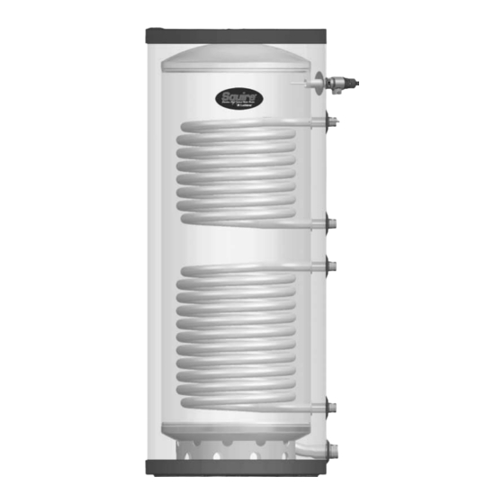
304L Stainless Steel Insulation Polyurethane Jacket Polypropylene / ABS Figure 1-1 Lochinvar SDT and SET Series Indirect Water Heaters 1. RELIEF VALVE CONNECTION 2. HOT WATER OUTLET 3. BOILER WATER IN 4. BOILER WATER OUT 5. DRAIN / COLD WATER INLET 6. -
Page 5: Pre-Installation
Max. installed in a drain pan suitable for water heaters. Lochinvar shall not be held liable for any such water damage. The tank may be located some distance from the boiler... -
Page 6: Boiler Side Piping (Sdt Models)
Boiler Side Piping (SDT models) Figures 3-1 thru 3-4 show typical boiler side piping for several common situations. Regardless of which system is used it is imperative that the flow rates called for in Table 3C are developed through the coil. This requires properly sized piping and a properly sized pump. -
Page 7: Table 3C - Pressure Drop Values
Boiler Side Piping (SDT models) Table 3A Pressure Drop Chart SDT/SET065-080 Table 3A Pressure Drop Chart SDT/SET065-080 SDT / SET065 - 080 FRICTION LOSS SDT / SET065 - 080 FRICTION LOSS 10.00 10.00 8.00 8.00 6.00 6.00 4.00 4.00 2.00 2.00 0.00 0.00... -
Page 8: Piping Diagrams
Boiler Side Piping (SDT models) Figure 3-1 Piping Diagram Zoned with Circulators PRESSURE REDUCING VALVE BACKFLOW PREVENTER MAKE UP WATER SYSTEM SUPPLY (WHEN USED) AIR SEPARATOR EXPANSION TANK NOT TO EXCEED 4 PIPE DIA. DRAIN POINT OR A MAXIMUM OF 12" APART (TYPICAL) BALL VALVE (TYPICAL) - Page 9 Boiler Side Piping (SDT models) Figure 3-2 Piping Diagram Zoned with Valves PRESSURE REDUCING VALVE BACKFLOW PREVENTER MAKE UP WATER SYSTEM SUPPLY SENSOR (WHEN USED) AIR SEPARATOR EXPANSION TANK NOT TO EXCEED 4 PIPE DIA. DRAIN POINT OR A MAXIMUM OF 12" APART (TYPICAL) Y-STRAINER BALL VALVE...
- Page 10 SDT/SET Installation & Operation Manual Boiler Side Piping (SDT models) Figure 3-3 Knight Boiler Primary / Secondary Piping Please note that these illustrations are meant to show system piping concept only, the installer is responsible NOTICE for all equipment and detailing required by local codes.
- Page 11 Boiler Side Piping (SDT models) Figure 3-4 Multiple Tank Connections PRESSURE REDUCING VALVE BACKFLOW PRESSURE PREVENTER GAUGE MAKE UP WATER AIR SEPARATOR SYSTEM SUPPLY SENSOR SYSTEM SYSTEM BALL VALVE CIRCULATOR (TYPICAL) SYSTEN CIRCULATOR EXPANSION TANK DRAIN POINT (TYPICAL) UNION (TYPICAL) TEMPERATURE/ PRESSURE GAUGE Please note that these illustrations are meant to show system piping concept only, the installer is responsible...
-
Page 12: Domestic Side (Tank) Piping
Domestic Side (Tank) Piping Basic Domestic Piping Figure 4-2 on page 15 shows typical domestic water piping for a tank. The function of the components shown are as follows: Shut-off valves (recommended) - Used to isolate the tank for servicing. Backflow Preventer (required by some codes) - Used to prevent water from backing out of the tank and into the main potable water supply in the event that inlet... -
Page 13: Anti-Scald Valves (Mixing Valves)
BTU discharge capacity not less than shown in Table 4A, page 14. - Page 14 Determine T&P relief valve size by the following specifications, unless they conflict with local codes: SDT/SET065/080/119 - 3/4" NPT with a minimum CSA Rating of 200,000 Btu/hr. The Lochinvar SDT/SET series water NOTICE heaters will absorb/store less than 200,000 Btu/hr when domestic water outlet temperature is 210°F and boiler water...
- Page 15 Domestic Side (Tank) Piping Figure 4-2 Recommended Domestic Water Piping SDT/SET models FROM BOILER TO BOILER (SDT MODELS ONLY) NOTE: UPPER COIL REPLACED WITH ELEMENT ON SET MODELS FROM SOLAR CHECK VALVE TO SOLAR TEMPERATURE / PRESSURE DRAIN GAUGE (TYPICAL) Please note that these illustrations are meant to show system piping concept only, the installer is responsible NOTICE for all equipment and detailing required by local codes.
-
Page 16: Electrical Connection
WARNING period of time while tank is dry! Be sure to ground the water heater. The preferred way to ground is to use rigid metal conduit between the main CAUTION panel and the water heater junction box with approved end fittings. The separate ground wire connection provided in the water heater junction box must also be grounded. -
Page 17: Wiring
Wiring (continued) Table 5A Wiring SET065-SET119 Model SET065 SET080 SET119 °C Rated for 90 Figure 5-2 Combination Thermostat and High Limit Control, SET 065-SET119 SERVICE GROUND SCREW LINE VOLTAGE GROUND SCREW SET Wiring (Single Element) Volts / Phase Watts / AMPS Breaker Type 240 VAC / 1 Ph 4500 / 18.3... -
Page 18: Indirect Water Heater Sensor Setup (Knight Boiler)
Adjust the tank set point program. Reference the Knight Installation and Operation Manual for a detailed explanation of the tank set point program. Figure 5-3 Indirect Water Heater Controlled Using Tank Sensor SDT/SET Installation & Operation Manual Connect tank sensor Turn OFF the power to the unit. -
Page 19: Indirect Water Heater Controlled Using Aquastat And Zone
(continued) Indirect Water Heater Controlled Using Aquastat and Zone Circulator / Valve Install Aquastat to tank. Aquastat control (TST20016) can be ordered from your local Lochinvar distributor. Connect Aquastat to the zone controller for the Indirect Water Heater Zone. Adjust Aquastat to the desired temperature. -
Page 20: Start-Up And Check-Out
This is particularly important if the indirect water heater will be unused for an extended period of time after installation. Flush the indirect water heater by drawing at least three times its volume from the tank. 3. Make sure that all electrical connections are made correctly and that no exposed high voltage wiring is present. -
Page 21: Maintenance
Maintenance The Lochinvar SDT/SET series indirect water heater is an extremely simple device and as such requires very little maintenance. There are, however, several items which should be checked out on an annual or as needed basis to ensure a... -
Page 22: How To Properly Size Your Indirect Water Heater
Use the First Hour Rating (FHR) to properly size your Indirect Water Heater. The FHR is the amount of hot water in gallons the water heater can supply in the first hour of operation (starting with a tank full of hot water). The FHR is dependent on tank capacity, source of heat, and the size of the burner. -
Page 23: Performance Data Charts
Performance Data Table 8C First Hour Rating - 180°F Boiler Loop Water (Knight and Wall Mount Boilers, Upper Coil SDT Models) Model Boiler Supply Water Circulator Flow Domestic Outlet 115 140 115 140 115 140 115 140 115 140 115 140 115 140 115 140 115 140 115 140 115 140 115 140 115 140 115 140 115 140 WB050 45,000 117 92 117 92... - Page 24 Performance Data Table 8E First Hour Rating 200°F Boiler Loop Water (Universal Sizing, Upper Coil SDT Models) First Hour Rating - 200°F Boiler Loop Water (Universal Sizing - 45,000 - 295,000 Btu/hr / SDT065-119) Model SDT065 Boiler Supply Water Circulator Flow GPM 115 140 115 140 115 140 115 140 115 140 115 140 115 140 115 140 115 140 115 140 115 140 115 140 115 140 115 140 115 140 Domestic Outlet 45,000...
-
Page 25: High Output Piping
High Domestic Hot Water Usage When a large amount of hot water is required by a Domestic Hot Water system, the dual coil indirect water heater can be piped together when given the high volume needed to satisfy the high load demands. This is achieved by piping the boiler coil and solar coil together. -
Page 26: Series Piping
High Output Piping Figure 9-1 Indirect Boiler with Series Piping PRESSURE BACKFLOW REDUCING VALVE PREVENTER PRESSURE MAKE UP WATER SYSTEM SUPPLY SENSOR SEPARATOR SYSTEM SYSTEM BALL VALVE CIRCULATOR (TYPICAL) EXPANSION TANK DRAIN POINT (TYPICAL) Please note that these illustrations are meant to show system piping concept only, the installer is responsible NOTICE for all equipment and detailing required by local codes. - Page 27 High Output Piping Figure 9-2 Indirect Boiler with Parallel Piping PRESSURE REDUCING BACKFLOW VALVE PREVENTER PRESSURE GAUGE MAKE UP WATER SYSTEM SUPPLY SENSOR SEPARATOR SYSTEM SYSTEM BALL VALVE CIRCULATOR (TYPICAL) EXPANSION TANK DRAIN POINT (TYPICAL) (TYPICAL) TEMPERATURE/ Please note that these illustrations are meant to show system piping concept only, the installer is responsible NOTICE for all equipment and detailing required by local codes.
-
Page 28: Revision Notes
Revision Notes: Revision A (ECO C05788) initial release. Revision B (ECO C05936) reflects the addition of “High Output Piping” section on pages 25-27, Series and Parallel piping diagrams on pages 26-27, and new friction loss charts for SDT Series and Parallel on pages 26 and 27. Revision C (ECO C06300) reflects the update of tank images and additional CSA cautions on manual cover, “Connect tank sensor”...
Need help?
Do you have a question about the SQUIRE SDT/SET065 - 119 and is the answer not in the manual?
Questions and answers