
Subscribe to Our Youtube Channel
Related Manuals for STK Professional Audio VX1443-FDR


Summary of Contents for STK Professional Audio VX1443-FDR
- Page 1 VX1443-FDR/2043-FDR Integrated Series Recording / Live Sound Mixer. OWNER'S MANUAL ENGLISH...
-
Page 2: Table Of Contents
The VX1443-FDR/2043-FDR is designed for use in sound reinforcement(SR) or recording applications. The VX1443-FDR/2043-FDR has four submix buses plus main L/R, and four auxiliary buses. If can blend, combine and control a variably of audio input source, including microphones, electronic instruments and the audio devices such as CD players and analog or digital sound recorders. -
Page 3: Important Safety Instructions
2. Important Safety Instructions 1. Read Instructions- All the safety and operating instructions should be read before the device is operated. 2 Retain Instructions- The safety and operating instructions should be retained for future reference. 3. Heed Warnings- All warnings on this appliance and in the operating instructions should be adhered to. -
Page 4: Warranty Information
Save all packing materials For more information about warranty repair, until the claim has been settled. Customer Service Dept., please contact: The STK Professional Audio. STK Customer Service Department 369-2 KURAERI YANGCHON-MYUN KIMPO-CITY KYUNGGI-DO, KOREA. TEL : +82-(0)31-981-1788... -
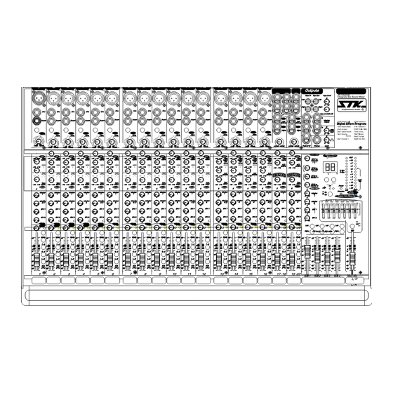
Page 5: Panel Descriptions
4. Panel Descriptions Monaural Input Channel > < FRONT PANEL(CHANNEL) Note: The operation of the VX2043-FDR Mixer is nearly identical. This manual will help you understand and get the most out of all "Quality Series" mixers. Monaural Input Channel 1. Mic Inputs. The microphone input to each channel strip is made through a standard 3-pin female Mic connector, XLR(3-pin)balanced input accepts microphone-level... - Page 6 4. Panel Descriptions 10. Monitor 1, 2 16. Main L/R Switch Adjusts the amount of channel input signal supplied This switch used to routed the channel signal to the to the Monitor 1 & 2 output Monitor send is post-EQ. main mix Left and Right buses.
- Page 7 4. Panel Descriptions A. Stereo Input Channel < Stereo Input Channel > 1. Left(Mono) Input. Accepts 1/4" TRS(tip/ring/sleeve) balanced input or TS(tip/sleeve) unbalanced sources at line level. 1/4" connector Tip is "Hot", Ring is "Cold" and Sleeve is "Shield". Input is routed to the Left output bus. In the absence of a plug in the Right Input(2), the Left Input signal is also provided to the Right Input, so that the channel functions as a mono channel.
- Page 8 4. Panel Descriptions 11. Mute Switch. 17. EFX Send 1,2. Mute When the switch is depressed ,the signal in Provides the unbalanced, line-level EFX Send 1,2 that channel strip is remove from the main Left/ output mixes on 1/4" phone jacks, for connection to Right mix buses, the solo buses(PFL) external effects or monitor systems.
- Page 9 4. Panel Descriptions < Master Section > B. Master Section 1. EFX1 to Main Mix. Stereo signals(from STEREO EFX RETURN 1) come through this TO MAIN MIX knob and continue on to the MAIN MIX Fader. 2. EFX2 to Main Mix. Stereo signals(form STEREO EFX RETURN2 and DSP EFFECT PROCESSOR) come through this TO MAIN MIX knob and continue on to the MAIN MIX FADER.
- Page 10 4. Panel Descriptions * 128 x oversampling DAC digital filter. mix" to the left and Right master outputs. * CD-quality professional sound a reality. 15. 7Band Stereo Graphic EQ. This equalizer used to shape the frequency spectrum APPLICATIONS of the main mix is the last thing si chain prior to * Long time delay and repeat for moslem church.
- Page 11 4. Panel Descriptions 27. Headphone Output Connect stereo headphones here for channel monitoring and curing. Control of Headphone output Level control(28). 28. Headphone output level You can control the output of Headphone. 29. Program Display. REVERBERATION EFFECTS(37) ECHO/DELAY EFFECTS(32) MODULATION EFFECTS(30) 01 Reverb Hall 2.0 sec.
- Page 12 The Right and Left main outputs are electronically machine or hard disk recorder for multi-track balanced, with Pin1 connected to ground, Pin2 to recording.(VX1443-FDR only) signal "Hot"(or "High" or "+") and Pin3 to signal "Cold"(or "Low" or "-"). With the master fader at untie, nominal output level is +4dBu.
-
Page 13: Connecting Your System
5. Connecting Your System Figure-1 CONNECTORS a. Female Combination Connector Your mixers uses several types of input and output connectors. 1. XLR Mic Input. Electronically balanced inputs accept a standard XLR male connector. Pin1=ground, pin2=hot or positive(+) and pin3=cold or negative(-) (see figure 1). These connectors should be utilized for low impedance microphones. -
Page 14: Operating Your System
6. Operating Your System CARE AND MAINTENANCE Your Quality Series Mixer is built to provide years of dependable service under demanding circumstances. It requires no internal maintenance but a common sense approach to its use will help you enjoy long and reliable operation. Here are some tips: 1. -
Page 15: System Hookup Diagrams
7. System Hookup Diagrams SOUND REINFORCEMENT We will bring the bass in on two channels: one will be a mic on the bass amp, the other direct injection from a direct box on the stage. The VX2043-FDR was definitely designed with sound The guitar will also have two feeds: one a mic reinforcement in mind. - Page 16 7. System Hookup Diagrams RECORDING The VX2043-FDR is a great recording and mixing console for a four-or eight-track project studio. Below you'll find the basic plan for connecting the VX2043-FDR for recording and some specific ideas Tracking on An for multi track sessions in Eight-Track.
- Page 17 7. System Hookup Diagrams Monitor Set Up keyboard keyboard Left Speaker Stereo Compressor/Limiter VS-15 MIC 1 MIC 2 Left Speaker 4-Track Recorder EFFECT VFX-299 V-3.5M Monitor AMP Stage Monitor Headphones Studio Monitors - 17 -...
- Page 18 7. System Hookup Diagrams Audio/Video Set up VQ-15N V-3.5M V-3.5M Monitor AMP Stage Monitor V-3.5M V-3.5M Monitor AMP Stage Monitor Headphones - 18 -...
-
Page 19: Block Diagram
8. Block Diagram... -
Page 20: Specifications
9. Specifications MODEL VX1443-FDR / 2043-FDR Inputs total 1443FDR:30 0.05% 2043FDR:36 Noise Mono Mic/Line Master Fader @Unity, -89dBu Stereo Line CH. Gain Down Tape 2 RCA Master Fader @Unity, -86dBu Aux Returns 2 Stereo CH. Gain @Unity Outputs Signal to Noise Ratio(ref+4) ≥90dB... - Page 21 Notes...
- Page 22 Notes...
- Page 23 Notes...
- Page 24 Owner's Manual For The STK VX1443/2043-FDR Mixing Console. Printed In Korea STK Professional Audio 11/07...
Need help?
Do you have a question about the VX1443-FDR and is the answer not in the manual?
Questions and answers