Table of Contents
Advertisement
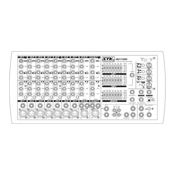
VM11T-DRV
VM11S-DRV
VM8-DRV
VM series Box Type Powered Mixer
OWNER'S MANUAL
VM11T-DRV
VM11T-DRV
ENGLISH
VM11T-DRV
VM11T-DRV
50~350
50~350
(msc)
(msc)
350
350
~1000(msc)
~1000(msc)
0
10
10
DRV DL
DRV DL
0~45
0~45
(%)
(%)
45~
45~
90(%)
90(%)
0
10
10
DRV FB
DRV FB
0.5~3.5
0.5~3.5
(sec)
(sec)
3.5~10
3.5~10
(sec)
(sec)
0
10
10
DRV RB
DRV RB
PEAK
PEAK
REV
REV
DLY
DLY
DRV MIX
DRV MIX
Advertisement
Table of Contents

Related Manuals for STK Professional Audio VM-11T DRV


Summary of Contents for STK Professional Audio VM-11T DRV
- Page 1 VM11T-DRV VM11S-DRV VM8-DRV VM series Box Type Powered Mixer OWNER'S MANUAL ENGLISH VM11T-DRV VM11T-DRV VM11T-DRV VM11T-DRV 50~350 50~350 (msc) (msc) ~1000(msc) ~1000(msc) DRV DL DRV DL 0~45 0~45 90(%) 90(%) DRV FB DRV FB 0.5~3.5 0.5~3.5 (sec) (sec) 3.5~10 3.5~10 (sec) (sec) DRV RB...
-
Page 2: Table Of Contents
Specifications ....................24-27 Ⅰ Introduction The new VM-11T DRV, VM-11S DRV and VM-8DRV mixers offer solid, feature-packed performance in a compact, economical format. The VM-11T DRV, VM-11S DRV features 11 independent channels, while the VM-8 DRV features 8 channels. Each channel incorporates a low impedance, XLR input and a high impedance quarter inch phone jack input. -
Page 3: Important Safety Instructions
Ⅱ Important Safety Instructions 1. Read Instructions- All the safety and operating instructions should be read before the appliance is operated. 2. Retain Instructions- The safety and operating instructions should be retained for future reference. 3. Heed Warnings- All warnings on this appliance and in the operating instructions should be adhered to. 4. -
Page 4: Warranty Information
For more information about warranty repair, please contact: Customer Service Dept., packing materials are not available for inspection by the carrier. Save all packing materials until the The STK Professional Audio. claim has been settled. STK Customer Service Department 250, ANAJI-RO, GYEYANG-GU FOR YOUR RECORDS INCHEON, KOREA. -
Page 5: Panel Description
Ⅳ Panel Descriptions VM-11TDRV The operation of the VM11T-DRV Triple powered 10. PAD Note: mixer is nearly identical. This manual will help you This switch attenuates the input signal by 10dB when understand and get the most out of all VM mixers. connecting a line level device to channels 1-7, or if the mic input is distorted turn-this switch on (the pressed-in position) MONO INPUT CHANNELS... -
Page 6: Panel Descriptions
7 band graphic equalizers are provided on the front panel and player or a CD player. The signals input to these jacks is sent may be used for stereo section Left signal of VM-11T DRV. to the ST bus 28. Graphic Equalizer(Right) 13. - Page 7 Ⅳ Panel Descriptions VM-11TDRV FRONT PANEL MASTER SECTION Digital Signal Processor Function and Features The STK digital reverbs gives the power to create original sounds with a wide range of effects. Effect patch(effect setting) can be stored in the internal memory, calling up any patch is quick and easy by linear potentiometer.
-
Page 8: Mono Input Channels
Ⅳ Panel Descriptions VM-11SDRV The operation of the VM11S-DRV Stereo powered mixer 10. PAD Note: is nearly identical. This manual will help you understand and This switch attenuates the input signal by 10dB when connecting a line get the most out of all VM mixers. level device to channels 1-7, or if the mic input is distorted turn-this switch on (the pressed-in position) MONO INPUT CHANNELS... - Page 9 Ⅳ Panel Descriptions VM-11SDRV 15. Left/Main, Right/Mon Out 6a. High The Left/Main and Right/Mon output 1/4" connectors are the The high frequency shelf control is set at 8kHz. You can final output for the master stereo mix and controlled by the increase or attenuate frequencies 8kHz(and above)up to 15dB.
- Page 10 Ⅳ Panel Descriptions VM-11SDRV FRONT PANEL MASTER SECTION Digital Signal Processor Function and Features The STK digital reverbs gives the power to create original sounds with a wide range of effects. Effect patch(effect setting) can be stored in the internal memory, calling up any patch is quick and easy by linear potentiometer.
- Page 11 Ⅳ Panel Descriptions VM-8DRV FRONT PANEL MASTER SECTION The operation of the VM8-DRV/VRM8-DRV Mono powered Note: mixer is nearly identical. This manual will help you 9. Aux In - Input to Aux Jack understand and get the most out of all VM mixers. The Aux In - Input to Aux phone jack is used to feed signals from an external source to the main bus and can be connected MONO INPUT CHANNELS...
- Page 12 Ⅳ Panel Descriptions VM-8DRV 16. EFX to Mon FRONT PANEL MASTER SECTION This master DSP EFX level control sent to Mon bus varies the amount of overall combined signal of the independent channels. 17. EFX to Main This master DSP EFX level control sent to main bus varies the amount of overall combined signal of the independent channels.
-
Page 13: Panel Description
Ⅳ Panel Descriptions Rear Panel 5. Right Out These two parallel speaker output jacks accept standard 1/4" two-conductor phone plugs, providing 300 watts of power at 4 ohms, or 200 watts at 8 ohms. (VM-11S DRVH:450watts/4ohms, 280watts/8ohms) Load impedances less than 4 ohms will not draw additional power and may cause the unit to go into protect mode. -
Page 14: Connecting Your System
Ⅴ Connecting Your System A. CONNECTORS B. SYSTEM HOOKUPS Your powered mixers uses several types of input and output Before you begin your connections, you must decide how you connectors. will configure your sound system, mono or stereo. Below are system variations that can be used with your powered mixer. - Page 15 Ⅴ Connecting Your System ■ Connecting main speaker If you select the two channel connection, the speaker connect to the SPEAKER L/R jacks. And select the BRIDGE connection, The speaker connect to SPEAKERS L+R BRIDGE jacks. Defend on the number of connected speakers. And the type of connection, speaker impedance requirements vary.
-
Page 16: Operating Your System
Ⅵ Operating Your System connect the tape out jack of your mixer to the input jacks of Powered Mono the tape recorder. Now that you have decided which mode and type of system 6. Connect the external effects device. operation you will use, You are ready to make your system If you are utilizing an external effects device, using standard connections and settings on your VM Mixer. - Page 17 Ⅵ Operating Your System are too strong and boost others that are too weak, or, in other 3. Set the input Level of the External Monitor words, to "Equalize" the seven different bands in their Equalizer(if applicable). relationship to each other. If you are using a separately powered monitor system, set the input level control of the equalizer to about 60%.
-
Page 18: System Hookup Diagram
Ⅶ System Hookup Diagram VM-11TDRV As a band with VM-11TDRV Here is an example of using the VM-11TDRV as a compact system for a band. FROM MONITOR SPEAKER OUT... - Page 19 Ⅶ System Hookup Diagram VM-11SDRV As a band with VM-11SDRV Here is an example of using the VM-11SDRV as a compact system for a band.
- Page 20 Ⅶ System Hookup Diagram VM-8DRV As a band with VM-8DRV Here is an example of using the VM-8DRV as a compact system for a band.
-
Page 21: Block Diagrams
Ⅷ Block Diagram VM-11TDRV... -
Page 23: Block Diagrams
Ⅷ Block Diagram VM-8DRV... -
Page 24: Specifications
Ⅸ Specifications VM-11TDRV&VM-11SDRV ■ General Specifications MODEL VM-11SDRV(H) VM-11TDRV Power Output Level(EIA) RL 4 2 x 330 (2 x 440 ) 3 x 300 RL 8 2 x 220 (2 x 300 ) 3 x 200 Total Harmonic Distortion f=1 , Rated output RL 4 0.05% Rated output RL 8 0.05%... -
Page 25: Input Specifications
Ⅸ Specifications VM-11TDRV&VM-11SDRV ♪Input specifications. Input level Actual Load For use with Input terminals Connector in mixer Nominal Max. before nominal Impedance Sensitivity (limit) clip(Main Out) MIC IN (1-9) -50 dBu -34 dBu 4 kohms ±1 dB XLR Jack LOW IMPEDANCE ohms mic (2.45 mV) (15.5 mV) -
Page 26: General Specifications
Ⅸ Specifications ■ General Specifications MODEL VM-8DRV Power Output Level(EIA) RL 4 300W RL 8 200W Total Harmonic Distortion f=1 , Rated output RL 4 0.05% Rated output RL 8 0.05% Main output +4 /600 0.08% Frequency Response 20 , 8 , 1 watt(Speaker Out) +1, -1.5 CH IN to Main OUT +1, -1.5... - Page 27 Ⅸ Specifications ♪Input specifications. Input level Actual Load For use with Input terminals Connector in mixer Nominal Max. before nominal Impedance Sensitivity (LIMIT) clip(Main Out) MIC IN (1-8) -50 dBu -34 dBu 4 kohms ±1 dB XLR Jack LOW IMPEDANCE ohms mic (2.45 mV) (15.5 mV)
- Page 28 Owner's Manual For The STK VM Series Powered Mixer. Printed In Korea STK Professional Audio DEC.2009...
Need help?
Do you have a question about the VM-11T DRV and is the answer not in the manual?
Questions and answers