
Related Manuals for Grizzly G3358


Summary of Contents for Grizzly G3358
- Page 1 MODEL G3358 MILLING/DRILLING MACHINE OWNER'S MANUAL WARNING: NO PORTION OF THIS MANUAL MAY BE REPRODUCED IN ANY SHAPE OR FORM WITHOUT THE WRITTEN APPROVAL OF GRIZZLY INDUSTRIAL, INC.
-
Page 3: Table Of Contents
Table of Contents SECTION 5: ACCESSORIES ......26 INTRODUCTION ..........2 SECTION 6: MAINTENANCE ......28 SECTION 1: SAFETY ........7 SECTION 7: SERVICE ........30 SECTION 2: CIRCUIT REQUIREMENTS ..10 SECTION 8: WIRING ........35 SECTION 3: SETUP ........11 SECTION 9: PARTS ........ -
Page 4: Introduction
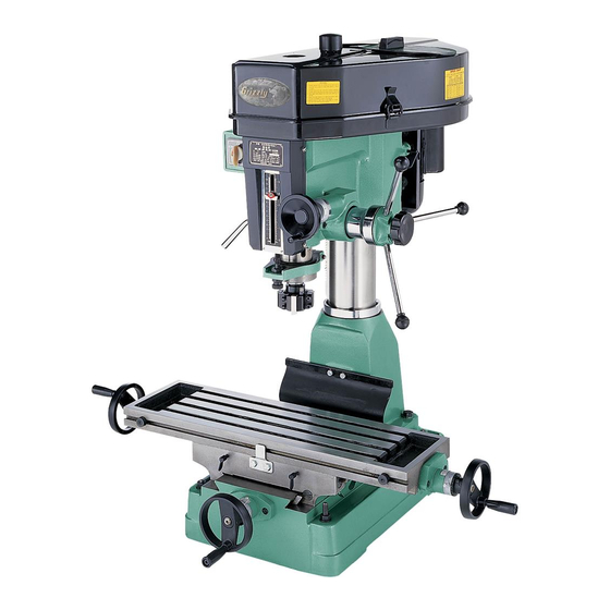
INTRODUCTION Functional Overview Foreword www.grizzly.com Contact Info... - Page 5 Identification Figure 1. A. Directional Switch Cast Iron Base G. Micro-Adjustment Lock Knob B. Micro-Adjustment Handwheel C. Depth Stop H. Quill Downfeed Levers— D. 3" Face Mill Longitudinal (X-Axis) Handwheel E. Longitudinal Stops Cross (Y-Axis) Handwheel—...
-
Page 6: Machine Data Sheet
MACHINE DATA SHEET Customer Service #: (570) 546-9663 · To Order Call: (800) 523-4777 · Fax #: (800) 438-5901 MODEL G3358 MILL / DRILL Weight................................540 lbs. Length/Width/Height......................... 41-1/2 x 41-1/2 x 43 in. Foot Print (Length/Width)..........................23 x 18 in. - Page 7 Spindle Travel.............................. 5 in. Swing..............................15-7/8 in. Longitudinal Table Travel........................19-3/4 in. Cross Table Travel............................7 in. Head Travel..............................12 in. Head Swivel............................360 deg. Turret Or Column Swivel........................360 deg. Max. Dist Spindle To Column........................7 in. Max. Dist Spindle To Table........................17-3/4 in. Drilling Cap For Cast Iron........................1-1/4 in.
- Page 8 Country Of Origin ..............................China Warranty ................................1 Year Serial Number Location ......................Label on Head Casting Assembly Time ..............................1 hour Clutch-Type Downfeed Mechanism Graduations in Inches 1/2" Drill Chuck 15/16" Lock Wrench 3" Face Milling Cutter Arbor Bolt Inner Hexagon Wrench R8-JT3 Tapered Bar...
-
Page 9: Section 1: Safety
Safety Instructions for Machinery... -
Page 11: Additional Safety For Mills
Additional Safety for Mills UNDERSTANDING CONTROLS. 10. MACHINE CARE AND MAINTENANCE. SAFETY ACCESSORIES. 11. DISCONNECT POWER. WORK HOLDING. 12. AVOIDING ENTANGLEMENT CHUCK KEY SAFETY SPINDLE SPEEDS. 13. TOOL HOLDING. 14. CLEAN-UP. POWER DISRUPTION. 15. CUTTING TOOL INSPECTION. SPINDLE DIRECTION CHANGES. STOPPING SPINDLE. -
Page 12: Section 2: Circuit Requirements
Figure 2. NOTICE Extension Cords The Model G3358 is prewired for 220V oper- ation. If you plan to operate your machine at 110V, the motor must be rewired (see Page 35). Full Load Amperage Draw... -
Page 13: Section 3: Setup
Wear safety glasses dur- Items Needed for ing the entire setup pro- cess! Setup The Model G3358 is a heavy machine. Serious personal injury may occur if safe moving meth- Description ods are not used. To be safe, get assistance and... - Page 14 Inventory Clean Up Crate Contents (Figure 3) Figure 4 For opti- mum performance from your machine, clean all moving parts or sliding contact surfaces. Gasoline and petroleum products have low flash points and can explode or cause fire if used to clean machinery.
-
Page 15: Site Considerations
Site Considerations Moving & Placing Machine Workbench Load Machine Data Sheet To move your machine into position: Placement Location Figure 5 Figure 6 Figure 5. Figure 6. Children and visitors may be seriously injured if unsuper- vised around this machine. Lock entrances to the shop or disable start switch or When using power lifting equipment, make... - Page 16 Mounting Assembly Handwheels To mount the handwheels to the machine: Leadscrew Backlash Page 33. Figure Figure 7 Figure 9. Figure 7. Figure 8 Figure 10 Figure 8. Figure 10.
- Page 17 Hardware Recognition Chart...
- Page 18 Head Crank To mount the head crank to the machine: Figure 12. Figure 11 Feed Levers To mount the feed levers to the machine: Figure 13 Figure 11. Column Cap To install the column cap to the column: Figure 13. Figure 12...
-
Page 19: Drill Chuck Arbor
Drill Chuck Arbor Face Mill All types of milling cutters and drill bits are sharp. It is recommended that these not be handled directly. Use leather gloves or shop towels to hold sharp tooling to avoid To install the drill chuck: cuts to your hands. - Page 20 Test Run & Break In NOTICE Failure to follow spindle break-in proce- dures will likely cause rapid deterioration of the spindle and other related parts and may void the warranty. Troubleshooting Page 29 To break-in the spindle: To test run the machine: Lubrication Page Speed Changes...
-
Page 21: Section 4: Operations
WE STRONGLY REC- OMMEND that you read books, trade maga- zines, or get formal training before begin- ning any projects. Regardless of the con- tent in this section, Grizzly Industrial will not be held liable for accidents caused by lack of training. - Page 22 Micro-Adjustment Handwheel: Longitudinal Travel Handwheels: Locking Knob: Cross Travel Handwheel: Quill Downfeed Levers: Table Locks: Travel Stops: Figure 17. Head Crank: Figure 19. Table travel controls. Figure 18. Head crank.
- Page 23 To remove a collet or an arbor: Collet/Arbor To install a collet or an arbor: Figure 21 Figure 20 Figure 21. Figure 20.
-
Page 24: Spindle Height
Spindle Height To lock the spindle: To operate the micro-adjustment handwheel: Figure 23 Figure Figure 23. Figure 22. - Page 25 Headstock Height Depth Stop To calibrate the depth stop: To adjust the headstock height: Figure Figure 24 Figure 25 Figure 24. Figure 25.
- Page 26 Speed Changes Figure 27 Figure 29 To change spindle speeds: Figure 26 Figure 27. see chart below Figure 26. Position Position Figure 28.
-
Page 27: Graduated Dials
Graduated Dials Cutting Speeds for High Speed Steel (HSS) Cutting Tools Example: Figure 30 Note: MACHINERY'S HANDBOOK Figure 29. Failure to follow RPM and feed rate guide- lines may threaten operator and bystander safety from ejected parts or broken tools. Figure 30. -
Page 28: Section 5: Accessories
SECTION 5: ACCESSORIES H2689—R-8 Quick Change Collet Set G1076—52-PC. Clamping Kit Figure 33. G9324—Boring Head Combo Set Figure 31. G9299—10" Yuasa-Type Rotary Table Figure 34. Figure 32. - Page 29 G2861—Face Mill G5641—1-2-3 Blocks G4051—Carbide Insert for Face Mill G9815—Parallel Set H5556—Edge Finder Set Figure 35. Figure 37. G9760—20-PC. 2 & 4 Flute TiN End Mill Set. G9765—9-PC. Ball End Mill Set Figure 36. Figure 38.
-
Page 30: Section 6: Maintenance
SECTION 6: MAINTENANCE Cleaning and Protecting Always disconnect power to the machine before performing maintenance. Failure to do this may result in serious person- al injury. Schedule Daily Check: Page 28... - Page 31 Lubrication V-Belts Points requiring periodic lubrication are: Figure 40 The main column. The quill. The quill pinion. The table leadscrews. Ball Oilers. Figure 39 Ways. Figure 40. Belt tension. Figure 39. Ball oiler locations.
-
Page 32: Section 7: Service
SECTION 7: SERVICE Troubleshooting Motor & Electrical... - Page 33 Motor & Electrical (Continued)
- Page 34 Operation and Work Results Page 33...
-
Page 35: Return Spring
Return Spring The spring’s tail is located on the perim- Figure 42 eter of the spring housing. This part may be sharp! Use leather gloves or a heavy shop towel to cover the tail while loading or unloading return spring pressure. Failure to use such precautions may result in per- sonal injury. -
Page 36: Leadscrew Backlash
To adjust the Y-axis leadscrew: Leadscrew Backlash Gibs To adjust the X-axis leadscrew: Figure Figure 43. Figure 44. Gib adjustment screw locations. -
Page 37: Section 8: Wiring
GROUNDED CIRCUIT. SHOCK HAZARD. 6. EXPERIENCING DIFFICULTIES. MOTOR WIRING. NOTICE The photos and diagrams included in this section are best viewed in color. You can view these pages in color at www.grizzly.com. -
Page 38: Wiring Diagram
110V 5-30 Plug (As Recommended) Ground 220V 6-15 Plug (As Recommended) Figure 45. Switch wiring (both sides shown). FWD/OFF/REV View this page in color at SWITCH (Both Sides Shown) www.grizzly.com. You MUST read and understand the Electrical Safety Instructions on Page 33. -
Page 39: Section 9: Parts
SECTION 9: PARTS Main Parts Breakdown 1000 Series... -
Page 40: Main Parts List
Main Parts List REF PART # DESCRIPTION PART # DESCRIPTION 1001 P33581001 DRAW BAR 7/16-20 X 402MM 1056 P33581056 SPACER 1002 P33581002 SPINDLE LOCK NUT 1057 P33581057 NAME PLATE 1003 P33581003 SPINDLE PULLEY 1058 P33581058 HEAD HANDLE 1004 P33581004 BELT BOTTOM COVER 1059 P33581059 WORM SHAFT... - Page 41 Main Parts List (continued) PART # DESCRIPTION PART # DESCRIPTION 1101 P33581101 COLUMN GEAR COVER 1145 PSS31M SET SCREW M5-.8 X 8 1102 P33581102 LIMIT PLATE 1146 P33581146 KNURLED SCREW M5-.8 X 12 1103 P33581103 SPRING COVER 1147 PSB24M CAP SCREW M5-.8 X 16 1104 P33581104 COILED SPRING...
- Page 42 Base Parts Breakdown 1000 Series...
-
Page 43: Base Parts List
Base Parts List REF PART # DESCRIPTION REF PART # DESCRIPTION 1146 P33581146 KNURLED SCREW M5-.8 X 12 1220 P33581220 TABLE CLUTCH 1201 P33581201 TABLE HANDLE WHEEL 1222 P33581222 LEFT FLANGE 1202 P33581202 DIAL CLUTCH 1223 P33581223 LEAD SCREW NUT 1203 P8103 THRUST BEARING 8103 1224 P33581224... -
Page 44: Label Breakdown And List
MUST maintain the original location and readability of the labels on the machine. If any label is removed or becomes unreadable, REPLACE that label before using the machine again. Contact Grizzly at (800) 523-4777 or www.grizzly.com to order new labels. -
Page 47: Warranty And Returns
WARRANTY AND RETURNS...
Need help?
Do you have a question about the G3358 and is the answer not in the manual?
Questions and answers