Table of Contents
Advertisement
Quick Links
Advertisement
Table of Contents

Related Manuals for PACOM SmartIP-4E


Summary of Contents for PACOM SmartIP-4E
- Page 3 Network Video Recorder WARNING RISK OF ELECTRIC SHOCK DO NOT OPEN WARNING: TO REDUCE THE RISK OF ELECTRIC SHOCK, DO NOT REMOVE COVER (OR BACK). NO USER-SERVICEABLE PARTS INSIDE. REFER SERVICING TO QUALIFIED SERVICE PERSONNEL. The lightning flash with arrowhead symbol, within an equilateral triangle, is intended to alert the user to the presence of uninsulated "dangerous voltage"...
-
Page 4: Important Safeguards
User’s Manual Important Safeguards 1. Read Instructions 13. Servicing All the safety and operating instructions should be read before the Do not attempt to service this equipment yourself. Refer all servicing to appliance is operated. qualified service personnel. 2. Retain Instructions 14. -
Page 5: Table Of Contents
Network Video Recorder Table of Contents Chapter 1 — Introduction ......................1 Feature ........................... 1 Chapter 2 — Installation ......................3 Package Contents ........................3 Required Installation Tools ....................3 Audio Out ........................... 3 Video Out ........................... 4 Video Input......................... 4 Network Port ........................ - Page 6 User’s Manual General ..........................12 Date/Time ........................21 User ..........................23 Storage ..........................24 Recording Setup ........................26 General ..........................26 Schedule .......................... 27 Pre-Event ......................... 29 Network Setup ........................30 General ..........................30 IP Address ........................31 DVRNS ..........................32 RTSP ..........................
- Page 7 Network Video Recorder Clip-Copy ......................... 66 Appendix ..........................69 USB Hard Disk Drive Preparation ..................69 Time Overlap ........................69 WebGuard ..........................70 Web Monitoring Mode ..................... 71 Web Search Mode ......................72 Map of Screens ........................74 Troubleshooting ........................75 System Log Notices ......................
- Page 8 User’s Manual Figure 35 : Camera – Profile (Advanced Mode) setup screen..............52 Figure 36 : Camera – Upgrade setup screen..................53 Figure 37 : Live Monitoring menu......................55 Figure 38 : Select Playback Camera menu..................... 59 Figure 39 : Search menu.
-
Page 9: Chapter 1 - Introduction
Network Video Recorder Chapter 1 — Introduction Feature Your color network video recorder (NVR) provides recording capabilities for four or eight network camera inputs. It provides exceptional picture quality in both live and playback modes, and offers the following features: ... - Page 10 User’s Manual...
-
Page 11: Chapter 2 - Installation
Network Video Recorder Chapter 2 — Installation Package Contents The package contains the following: Network Video Recorder Power Cord and Power Adaptor (NVR, PSE) Quick User Manual RAS Software CD (User’s Manual included) USB Mouse ... -
Page 12: Video Out
User’s Manual NOTE: It is the user’s responsibility to determine if local laws and regulations permit recording audio. The NVR does not have amplified audio output, so you will need a speaker with an amplifier. The NVR does not have a pre-amplifier for audio input, so the audio input should be from an amplified source, not directly from a microphone. -
Page 13: Alarm Input/Output
Network Video Recorder Alarm Input/Output NOTE: To make connections on the Alarm Connector Strip, press and hold the button and insert the wire in the hole below the button. After releasing the button, tug gently on the wire to make certain it is connected. To disconnect a wire, press and hold the button above the wire and pull out the wire. - Page 14 User’s Manual...
-
Page 15: Chapter 3 - Configuration
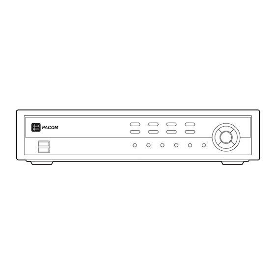
Network Video Recorder Chapter 3 — Configuration NOTE: Your NVR should be completely installed before proceeding. Refer to Chapter 2 — Installation. Front Panel Controls Figure 3 : 8-Channel NVR front panel. Camera Buttons Arrow Buttons Play/Pause Button Menu Button PTZ/Zoom Button Group/Sequence Button Search Button... -
Page 16: Play/Pause Button
User’s Manual Play/Pause Button In the live monitoring mode, pressing the button freezes the current screen and the screen displays icon. When in the playback mode, pressing the button plays back images at regular speed or pauses playing video. Pressing the button selects a highlighted item or completes an entry that you have made during system setup. -
Page 17: Remote Control Buttons
Network Video Recorder A USB mouse can be connected to one of the ports. You can use the mouse to navigate through the screens and menus much like you would on a computer. Remote Control Buttons ID Button Camera Buttons Status Button Zoom/Focus Buttons Search Button... -
Page 18: Arrow Buttons
User’s Manual Arrow Buttons These buttons are used to navigate through menus and GUI. You can also use them to change numbers by highlighting a number in the menu and using the Up and Down arrow buttons to increase or decrease the number’s value. Pressing the Left and Right buttons moves through screen pages in the Live Monitoring mode and Search mode. -
Page 19: Log Button
Network Video Recorder Log Button Pressing the button displays the Login or Logout screen. Enter Button (Enter) button selects a highlighted item or completes an entry that you have made during system setup. This button is also used to enter the Cameo mode in the Live Monitoring mode or Search mode. Zoom Button Pressing the button zooms the current image on the screen. -
Page 20: Setup Screen
User’s Manual NOTE: To log the user out of the system, press the button or move the mouse pointer on the right edge MENU of the screen and then select (Logout) in the Live Monitoring menu. The Logout screen displays asking you to confirm whether or not you want to log out the current user. -
Page 21: Figure 8 : System - General Setup Screen
Network Video Recorder Figure 8 : System – General setup screen. In the General screen, you can name the site location, assign a System ID number, select the language the screens are displayed in, display software version number, upgrade the software, show the System Log, display recorded time data, and clear all data. - Page 22 User’s Manual You can import saved NVR settings or export the current NVR settings. To import saved NVR settings, connect the USB device containing the setup file (.dat) to the NVR. Highlight Setup – Import… and press the button. Select the desired setup file and press the Import button to import the selected settings and change the NVR settings accordingly.
- Page 23 Network Video Recorder Highlighting Clear All Data and pressing the button will clear all video data. You will be asked to verify that you wish to clear all data before the NVR erases the video data. Clear All Data will not clear the System Log. Highlight System Shutdown and press the button.
- Page 24 User’s Manual Date/Time Setup Date: Set the system date and select the date format. Time: Set the system time and select the time format. Time Zone: Select your time zone. Use Daylight Saving Time: Selecting the box sets the system to use daylight saving time. NOTE: The Date/Time will be set, and the clock will start when you click the Next button.
- Page 25 Camera Registration (SEARCH & INITIALIZE) No.: Select the camera you want to register. Channel: Select the camera channel. Camera Registration (PASSWORD) Password: Enter the password (default: no password or pacom) to be assigned to the camera. Confirm: Confirm the password.
- Page 26 User’s Manual Camera Registration (END) If the camera registration has been completed, select the Next button. Record Video Quality Setup Select the desired video quality profile from: – Standard Recording Profile – Higher Video Quality Priority Profile – Longer Recording Time Priority Profile NOTE: The higher quality setting requires more storage space.
- Page 27 Network Video Recorder Select the Finish button to finish the Quick Setup Wizard and select the Go to Network Setup button to start the Network Setup. If you selected the Go to Network Setup, select the Next button to start the Network Setup Wizard.
- Page 28 User’s Manual Internet Connection Select whether or not your NVR is connected to the Internet. LAN Setup Select between Auto Configuration and Manual Configuration for network configuration, and then select the Test button to test the network configuration you selected. NOTE: Selecting Auto Configuration allows the NVR to automatically obtain LAN parameters (IP address, Gateway, Subnet Mask and DNS Server address).
-
Page 29: Date/Time
Network Video Recorder NOTE: The NVR name you entered should be checked by selecting Check, otherwise the DVRNS changes will not be saved. When entering no name or a name already registered on the DVRNS server, an error message displays. Select the Finish button to finish the Setup Wizard. - Page 30 User’s Manual Highlight the Format box beside Date and press the button. Select from the three available date formats and press button to save your selected format. Highlight the first box beside Time and press the button. The individual sections of the time will highlight. Use the Up and Down arrow buttons to change the number.
-
Page 31: User
Network Video Recorder User Highlight User and press the button. The User setup screen displays the authorized groups and users. You can add and delete groups and users. When adding a group, you can assign authority levels to the group. Figure 10 : System –... -
Page 32: Storage
User’s Manual Highlighting the Authority box and pressing the button will toggle between all authority levels being turned On and Off. Highlighting the individual authority level boxes and pressing the button will toggle between that authority level being turned On and Off. -
Page 33: Figure 11 : System - Storage Setup Screen
Network Video Recorder Figure 11 : System – Storage setup screen. The information in the Type column describes the storage device. The capacity of the storage device is displayed in the Capacity column. The Format column displays whether the device is used for recording (Record) or not (Not Using). Not formatted indicates the device is not formatted. -
Page 34: Recording Setup
User’s Manual Recording Setup General Highlight General and press the button, and the General setup screen appears. Figure 12 : Record – General setup screen. Highlighting Recycle and pressing the button toggles between On and Off. In the Recycle mode, the NVR records over the oldest video data once all available storage space has been used. -
Page 35: Schedule
Network Video Recorder CAUTION: When more than one disk is installed in the unit, the NVR records video on the disks sequentially based on time. And these sequentially recorded videos have the advantage that you can search recorded video easily even though a disk is removed from the unit. -
Page 36: Figure 14 : Schedule - Settings (Advanced Mode) Setup Screen
User’s Manual Highlight the box under the Day heading and press the button to change the days that the scheduled recording will take place. Choose from: Sun, Mon, Tue, Wed, Thu, Fri, Sat, M~F, Hol and All. Highlight the box under the Range heading and press the button to change the time range that the scheduled recording will take place. -
Page 37: Pre-Event
Network Video Recorder Highlight the box under the heading and press the button to delete the recording settings. You will be asked to confirm that you want to delete the settings. Highlight Default… and press the button. The Default screen appears. Highlighting boxes under Profile and pressing the button allows you to select the profile you would like to record for the associated event. -
Page 38: Network Setup
User’s Manual Network Setup General Highlight General and press the button, and the General setup screen displays. Figure 16 : Network – General setup screen. You can limit the network bandwidth settings so that system does not consume too much network bandwidth. Highlight the box beside Network Bandwidth Limit and press the Up and Down arrow buttons to set the desired maximum bandwidth from 50Kbps to 1Gbps. -
Page 39: Ip Address
Network Video Recorder IP Address Highlight IP Address and press the button, and the IP Address setup screen displays. Figure 17 : Network – IP Address (Manual) setup screen. Highlight the box beside Type and press the button. You can select the type of network configuration from: Manual, DHCP and ADSL (with PPPoE). -
Page 40: Dvrns
User’s Manual Highlight Use UPnP and press the button to toggle between On and Off. When it is On, port forwarding from the NAT (Network Address Translation) device to the NVR will be enabled automatically via UPnP (Universal Plug and Play) service. -
Page 41: Figure 18 : Network - Dvrns Setup Screen
Network Video Recorder Figure 18 : Network – DVRNS setup screen. Highlight Use DVR Name Service and press the button to toggle between On and Off. NOTE: The DVRNS (DVR Name Service) allows the NVR to use Dynamic IP addresses for remote connection. When this feature is On, you can access your NVR remotely using the NVR name instead of its IP address. -
Page 42: Rtsp
User’s Manual RTSP Highlight RTSP and press the button. The RTSP setup screen displays. Figure 19 : Network – RTSP setup screen. Highlight Enable RTSP (Real-Time Streaming Protocol) and press the button to toggle between On and Off. You will be able to change the settings if Enable RTSP is enabled. Highlight the box beside RTSP Port and press the button. -
Page 43: Notification
Network Video Recorder Notification Highlight Notification and press the button. The Notification setup screen displays. Figure 20 : Network – Notification setup screen. You can add and edit notification schedules. Highlight the + and press the button to add a schedule. Highlighting the boxes under the Column heading and pressing the button allows you to edit the information in those boxes. - Page 44 User’s Manual Highlight Mail – Setup and press the button, and the Mail screen appears. The NVR can be set up to send an email when an event occurs. The Mail account can be turned On or Off by highlighting the boxes under the No.
-
Page 45: Event Setup
Network Video Recorder Highlight the box beside Sender and enter the sender’s e-mail address. Use the virtual keyboard to enter the e-mail address. NOTE: The e-mail address must include the “@” character to be a valid address. Highlight the Test box and press the button to test emailing with the current settings you made. - Page 46 User’s Manual NOTE: The following description is for Motion setup. Video motion detection can be turned On or Off for each camera. Highlighting the box under the Sensitivity heading and pressing the button allows you to adjust the NVR’s sensitivity to motion for Daytime and Nighttime independently.
-
Page 47: Figure 22 : Event - Video-Analytics (Tripzone) Setup Screen
Network Video Recorder NOTE: The following description is for TripZone setup. Figure 22 : Event – Video-Analytics (TripZone) setup screen. Highlighting the box under the Sensitivity heading and pressing the button allows you to adjust the NVR’s sensitivity to tripzone detection for Daytime and Nighttime independently. -
Page 48: Figure 23 : Event - Video-Analytics (Tampering) Setup Screen
User’s Manual NOTE: The record action for motion events will not be affected by the TripZone Ignoring function. Highlighting Daytime Setup and pressing the button allows you to set up the Daytime range. Highlight the box beside Daytime and press the button. -
Page 49: Alarm-In
Network Video Recorder Alarm-In Highlight Alarm-In and press the button, and the Alarm-In setup screen appears. Figure 24 : Event – Alarm-In setup screen. The alarm terminal strip on the back of the NVR has inputs associated with each alarm. You can set up each input on the Alarm-In screen. -
Page 50: System Event
User’s Manual Figure 25 : Event – Video Loss setup screen. Highlight the box under the Actions and press the button. The NVR can be set to react to video loss differently for each camera. Each camera can be associated with another camera, trigger an Alarm-Out connector, sound the NVR’s internal buzzer, and/or notify a number of different devices. -
Page 51: Device Setup
Network Video Recorder Highlighting Schedule On and pressing the button toggles On and Off. When set to On, you can select the day, time range and interval that you want the NVR to run self-diagnostics on the recorder. The Interval can be selectable from 1 min. to 7 days or Never. -
Page 52: Display Setup
User’s Manual Highlighting the boxes under the Column heading and pressing the button allows you to edit the information in those boxes. Highlighting the boxes under the Day box and pressing the button allows you to select the days that the alarm schedule will be active. -
Page 53: Monitor
Network Video Recorder Free Space – The icon displays when the NVR is in the Recycle mode, and the percentage of available storage space displays when the NVR is not in the Recycle mode. Date/Time – The current date and time information displays. ... -
Page 54: Status Setup
User’s Manual Highlight Event Monitoring On and press the button. Pressing the button toggles between On and Off. When it is On, the NVR will display the camera associated with the event when an event occurs. Highlight the box beside Set Resolution to Manual Mode and press the button. -
Page 55: Storage
Network Video Recorder Storage Highlight Storage and press the button, and the Storage setup screen appears. Figure 31 : Status – Storage setup screen. The Type column displays the type of storage device. The Disk Bad column displays the percentage of bad sectors. Not formatted indicates the device is not formatted. The Temperature column displays the temperature of the storage device. -
Page 56: Figure 32 : Camera - Network Camera Setup Screen
User’s Manual Figure 32 : Camera – Network Camera setup screen. Highlight the box under the Network Camera List heading and press the button to displays the information of selected network cameras. Highlight the box under the heading and press the button to delete registered network cameras. -
Page 57: General
Network Video Recorder Highlight the box beside User/Password and press the button. A virtual keyboard appears allowing you to enter the user ID and password. Highlight Apply to All Authentication and press the button to apply the same authentication information to all the network cameras in the list. When selecting multiple network cameras in the list, selecting Skip skips the authentication settings for the current network camera and displays the Camera Authentication screen of the next network camera. - Page 58 User’s Manual CAUTION: The camera connection will be disconnected temporarily after changing the SSL settings. Highlight the box under the Password heading and press the button to change the password. Highlight the box beside Password and press the button. A virtual keyboard appears allowing you to enter the password.
-
Page 59: Profile
Network Video Recorder Exposure AE Target Gain: Set the target gain for the exposure compensation. Local Exposure: Set the local exposure. Anti-Flicker: Set to the same frequency as the lighting when the AC power is used for the lighting such as a fluorescent lights. -
Page 60: Figure 34 : Camera - Profile (Simple Mode) Setup Screen
User’s Manual Figure 34 : Camera – Profile (Simple Mode) setup screen. Highlight the box beside Select Mode box and press the button. You can select between Simple Mode and Advanced Mode. Selecting Advanced Mode allows you to set up individual profiles for each camera. NOTE: The following description is for Simple Mode setup. -
Page 61: Upgrade
Network Video Recorder Selecting Advanced Mode allows you to set up individual profiles for each camera. Set up the Resolution, Quality and IPS for each profiles. Setting up the profiles is almost identical to setting up the profiles for Simple Mode. Upgrade Highlight Upgrade and press the button, and the Upgrade setup screen appears. - Page 62 User’s Manual...
-
Page 63: Chapter 4 - Operation
Network Video Recorder Chapter 4 — Operation NOTE: This chapter assumes your NVR has been installed and configured. If it has not, please refer to Chapters 2 and 3. The front panel controls are described in Chapter 3 — Configuration. Turning on the Power Once you have installed the NVR following the instructions in Chapter 2 —... - Page 64 User’s Manual Previous Group, Next Group: Selecting (Display) → Previous Group or Next Group moves to the previous or next page. Edit Group: Selecting (Display) → Edit Group enters to the Active Cameo mode. Refer to the following Active Cameo Mode section for details.
-
Page 65: Active Cameo Mode
Network Video Recorder NOTE: Any image adjustments you make will be applied to both the live video on the monitors and the recorded video. The Camera Menu also can be displayed by clicking the right mouse button on the screen while in the live monitoring mode. -
Page 66: Covert Camera
User’s Manual Event monitoring lasts for the dwell time set for event recording. After the dwell time has elapsed, the monitor returns to the previous screen unless another event has occurred. If you want to return to the live monitoring mode before the dwell time has elapsed, press the button or one of the camera buttons. -
Page 67: Playing Recorded Video
Network Video Recorder Playing Recorded Video If a user who has Search authority logs into the system, the user can view recorded image. Once video has been recorded, you can view it by pressing the (Play/Pause) button. The NVR supports the Triplex function: monitoring, recording and playing back at the same time. Pressing the button when in one of the multi-view formats enters the Triplex mode and displays the Select Playback SEARCH Camera menu. -
Page 68: Searching Video
User’s Manual NOTE: The playback speed “x1” will not be supported in the 3x3 display mode. Searching Video While in the search mode, pressing the button displays the following Search menu on the right edge of the MENU screen. Pressing the button again hides the menu. - Page 69 Network Video Recorder Display Screen Format 2x2, Screen Format 3x3: Selecting (Display) → Screen Format 2x2 or Screen Format 2x2 displays the cameras in the selected multiview screen mode (2x2, 3x3). Previous Group, Next Group: Selecting (Display) → Previous Group or Next Group moves to the previous or next page.
-
Page 70: Event Log Search
User’s Manual Event Log Search Figure 40 : Event Log Search screen. The NVR maintains a log of each time the Alarm Input port is activated. The Event Log Search screen displays this list. Use the arrow buttons to highlight the event for which you would like to see video. There is no determined user authority to display the Event Log Search screen, however, the event video will not be played unless a user with Search authority logs into the system . -
Page 71: Record Table Search
Network Video Recorder Highlight the box beside Check Time Overlap and press the button. It toggles between On and Off. You will only be able to turn the Check Time Overlap on or off if a user-defined date and time is set to From and To. If the NVR’s date and time have been reset, it is possible for the NVR to have more than one overlapping start and stop time. - Page 72 User’s Manual Recording information about video images currently displayed on the screen displays on the recording status bar. A grey vertical line indicates the current search position. To search specific video, move the vertical line by using the Left or Right arrow buttons on the front panel or by clicking the mouse on the desired segment. If the NVR’s time and date have been reset to a time that is earlier than some recorded video, it is possible for the NVR to have more than one video stream in the same time range.
-
Page 73: Motion Search
Network Video Recorder Motion Search Figure 42 : Motion Search screen. The Motion Search… can be selected from the Search menu while the NVR displays the camera full screen. The Motion Search screen displays a list of motion events. Use the arrow buttons to highlight the event for which you would like to see video and press the (Play/Pause) button to display the video associated with the selected event on the small search screen. -
Page 74: Bookmarks
User’s Manual NOTE: When setting the Museum Search Zone, the zone should be placed inside of the border line of the target object. If the selected block is placed on the border line, the sensitivity of the Museum Search may decrease. The zone should be placed or focused on the centre or, at least, within the outline of targeted object. -
Page 75: Figure 44 : Clip-Copy Screen
Network Video Recorder Figure 44 : Clip-Copy screen. The Data Source box displays the source from which you make a video clip copy. You can search video from the first to last recorded images, or you can set the start and stop times and dates. Highlight the box beside From and press the (Play/Pause) button to toggle between On and Off. - Page 76 User’s Manual NOTE: The file size for clip copy is limited to 30GB. When copying video clips larger than 2GB, the video clips will be save in units of 2GB. For example, 3 individual 2GB files will be created when saving a 6GB video clip.
-
Page 77: Appendix
Network Video Recorder Appendix USB Hard Disk Drive Preparation NOTE: The following description is for preparing a USB hard disk drive under Windows 2000. Preparing a USB hard disk drive under Windows XP, Window Vista and Window 7 is almost identical to Windows 2000. Connect the USB hard disk drive to your computer using the USB Cable. -
Page 78: Webguard
User’s Manual WebGuard WebGuard allows you to access a remote NVR, monitor live video images and search recorded video using Internet Explorer web browser anytime from virtually anywhere. Computer system requirements for using the WebGuard program are: ® ® ® ®... -
Page 79: Web Monitoring Mode
Network Video Recorder NOTE: There might be a problem with screen display or screen update due to low image transmission speed when using the Microsoft Windows Vista or higher operating system. In this situation, it is recommended that you disable the Auto Tuning capability of your computer. Run the Command Prompt with elevated administrator permissions (Go to the Start Menu →... -
Page 80: Web Search Mode
User’s Manual ⑩ Click the to set up the image drawing mode, OSD display and beep on/off. You can adjust the display speed by changing the image drawing mode, select OSD information to be displayed on the screen, and turn the NVR’s internal buzzer on and off from a remote site. - Page 81 Network Video Recorder ③ Position the mouse pointer on the WebSearch logo to see the version of the WebGuard program. ④ The NVR information window displays the time information of recorded data on the remote NVR and login information of WebGuard. ⑤...
-
Page 82: Map Of Screens
User’s Manual Map of Screens MENU SYSTEM General Date/Time User Storage RECORD General Schedule Pre-Event NETWORK General IP Address DVRNS RTSP Notification EVENT Video-Analytics Alarm-In Video Loss System Event DEVICE Alarm-Out DISPLAY Monitor STATUS Event Storage CAMERA Network Camera General Profile Upgrade... -
Page 83: Troubleshooting
Network Video Recorder Troubleshooting Problem Possible Solution Check power cord connections. No System Power Confirm that there is power at the outlet. Check power cord connections. No PoE Power Confirm that there is power at the outlet. ... -
Page 84: Error Code Notices
User’s Manual Error Code Notices System Upgrade Related Description Description Unknown error. Remote network error. File version error. Remote upgrade is not authorized. Operating system version error. Saving remote package failed. Software version error. Remote upgrade is cancelled by the user. Kernel version error. -
Page 85: Specifications
Network Video Recorder Specifications VIDEO Video Input Ethernet: 4 or 8 cameras HDMI: 1 HDMI Monitor Outputs VGA: 1 DB15 Video Resolution 1920x1080, 1280x1024, 1280x720, 1024x768 Record Speed 8-ch Model: 240ips @ 1920x1080 (8Mbps), 240ips @ 1280x720 (images per second) 4-ch Model: 120ips @ 1920x1080 (8Mbps), 120ips @ 1280x720 Playback Speed 120ips @ 1280x720, 60ips @ 1920x1080... - Page 86 Before making a warranty claim, ensure that you have read the “Troubleshooting” section of the Owner’s Manual. PACIFIC COMMUNICATIONS A division of Hills Holdings Limited ACN 007 573 417 Unit 10, 331 Ingles Street City Link Estate, PORT MELBOURNE VIC 3207, AUSTRALIA www.pacom.com.au...
- Page 87 WARRANTY TERMS Pacific Communications provides consumers with the following warranty in relation to this Equipment, in addition to complying with the requirements of any relevant legislation, including the Competition and Consumer Act 2010 (Cth) in Australia and the Consumer Guarantees Act 1993 in New Zealand (the Acts), except where a New Zealand consumer acquires the relevant Product for the purposes of a business.
Need help?
Do you have a question about the SmartIP-4E and is the answer not in the manual?
Questions and answers