Sign In
Upload
Download
Table of Contents
Contents
Add to my manuals
Delete from my manuals
Share
URL of this page:
HTML Link:
Bookmark this page
Add
Manual will be automatically added to "My Manuals"
Print this page
×
Bookmark added
×
Added to my manuals
Manuals
Brands
KTM Manuals
Engine
250 1998
Repair manual
KTM 250 1998 Repair Manual
Hide thumbs
1
2
3
4
5
6
7
8
9
10
11
12
13
14
15
16
17
18
19
20
21
22
23
24
25
26
27
28
29
30
31
32
33
34
35
36
37
38
39
40
41
42
43
44
45
46
47
48
49
50
51
52
53
54
55
56
57
58
59
page
of
59
Go
/
59
Contents
Table of Contents
Troubleshooting
Bookmarks
Table of Contents
1 1 General 2 3
Table of Contents
General
Bleeding the Cooling System
Definitions
Checking the Setting of the TVC System
Special Tools
Removing Engine / Refitting Engine
3.0 Dismantling Engine
Cylinder Head, Cylinder, Piston
Drain Gear Oil
Clutch Cover
Primary Drive
Ignition (Kokusan)
Kickstarter
Clutch Release Shaft
Engine Sprocket
Ignition (SEM)
Intake Flange, Reed Valve Housing
Crankshaft
Shift Mechanism, Transmission
4.0 Servicing on Individual Components
Servicing on Individual Components
Left Housing Half
Crankshaft
Piston
Piston Ring End Gap
Nikasil Coating of Cylinder
Exhaust Control in Clutch Cover
Preassembly of Clutch Cover
Reed Valve Housing, Intake Flange
Kickstarter
Transmission
Assembly of Countershaft
Clutch
Shift Mechanism
Preassembly of Shift Shaft
Ignition (Kokusan)
Spark Plug (NGK BR 8 ECM)
Check Stator and Pulse Generator (Kokusan)
Ignition (SEM)
Spark Plug (NGK BR 8 ECM)
Check Stator (SEM)
5.0 Engine Assembly
Engine Assembly
Assembly of Engine Housing
Clutch Release Shaft
Kickstarter
Primary Drive, Clutch
Clutch Cover
Piston and Cylinder
Clutch Discs, Pressure Cap
Cylinder Head
Mounting Ignition (Kokusan)
Mounting Ignition (SEM)
Adjusting Ignition Point (SEM)
Filling in Gear Oil
Starting Lever/Foot Shift Lever
Electrical
Checking the Voltage Regulator Tympanium
Checking the Voltage Regulator-Rectifier Shindengen
Checking the Voltage Regulator Kokusan
Checking the Capacitor
Ignition Coil Sem/Kokusan
CDI Unit
Trouble Shooting
Technical Data / Maintenance Schedule
Wiring Diagram
Advertisement
Quick Links
1
Engine Assembly
2
Checking the Voltage Regulator Tympanium
3
Checking the Voltage Regulator-Rectifier Shindengen
4
Technical Data / Maintenance Schedule
Download this manual
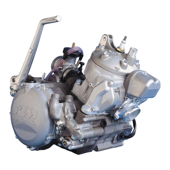
REPARATURANLEITUNG
REPAIR MANUAL
MANUALE DI RIPARAZIONE
MANUEL DE RÉPARATION
MANUAL DE REPARACIÓN
250 / 300 / 380
MOTOR
ENGINE
MOTORE
MOTEUR
MOTOR
'98
7. 97
ART. NR. 3.205.20
Table of
Contents
Previous
Page
Next
Page
1
2
3
4
5
Advertisement
Chapters
1 1 General 2 3
2
3.0 Dismantling Engine
12
4.0 Servicing On Individual Components
18
5.0 Engine Assembly
30
Table of Contents
Need help?
Do you have a question about the 250 1998 and is the answer not in the manual?
Ask a question
Questions and answers
Related Manuals for KTM 250 1998
Engine KTM 250-300 Spare Parts Manual
Ktm engine spare parts manual (28 pages)
Engine KTM EXC Repair Manual
Ktm automobile parts user manual (154 pages)
Engine KTM 250 MX Manual
Motor type 546 (12 pages)
Engine KTM 250 SX-F 2005 Repair Manual
(151 pages)
Engine KTM 250 SX-F 2006 Repair Manual
(126 pages)
Engine KTM 125 Repair Manual
(160 pages)
Engine KTM 2005 Spare Parts Manual
Ktm engine spare parts manual (28 pages)
Engine KTM 400-660 LC4 1998-2005 Repair Manual
(502 pages)
Engine KTM 690 LC4 2007 Repair Manual
(95 pages)
Engine KTM 500 LC4 Manual
1988, 1989 4-stroke engine type 580 (13 pages)
Engine KTM 450 SX-F Repair Manual
(132 pages)
Engine KTM S5-E Repair Manual
(23 pages)
Engine KTM 400/620 LCA Repair Manual
Motor engine (106 pages)
This manual is also suitable for:
300 1998
380 1998
Table of Contents
Save PDF
Print
Rename the bookmark
Delete bookmark?
Delete from my manuals?
Login
Sign In
OR
Sign in with Facebook
Sign in with Google
Upload manual
Upload from disk
Upload from URL


Need help?
Do you have a question about the 250 1998 and is the answer not in the manual?
Questions and answers