Table of Contents
Advertisement
Advertisement
Table of Contents

Related Manuals for Chuphotic KR6000


Summary of Contents for Chuphotic KR6000
- Page 1 KR Series UPS (6-10)KVA User’s Manual...
-
Page 2: Table Of Contents
3.3.1Display structure ....................- 14 - 3.3.2 Display interface....................- 14 - 3.3.3 KR6000L, KR(/B)1110, KR(/B)3110 appearance ..........- 15 - 3.3.4 KR6000, KR(/B)1110S, KR(/B)3110S appearance ..........- 17 - Installation ........................- 19 - Installation Notice ...................... - 19 - Installation process .................... - Page 3 4.10 System inspection and testing ................- 30 - 4.10.1 Check electrical connections ................- 30 - 4.10.2 UPS testing ..................... - 30 - 4.10.3 Connect with the load ..................- 30 - Using and Operation ....................- 31 - 5.1 Notes of using UPS .......................
-
Page 4: Safety Instruction
KR series(6-10kVA)user’s manual 1. Safety instruction Summary This chapter describes the safety symbols and safety precautions. Please read this chapter carefully before any operation of UPS in order to avoid of unsafe operation which will endanger personal safety or equipment damage. 1.1 Explanation of symbols Safety symbols please refer to table 1.1-1, these symbols are used to remind the reader to abide the safety operation during the installation, operation and... - Page 5 KR series(6-10kVA)user’s manual configuration, structure or components will affect the performance of UPS, if the user wants to make any change please consult with manufacturer or distributor in advance. Life risk! Contact high voltage and mains directly or indirectly through humidity objects will cause life risk.
- Page 6 KR series(6-10kVA)user’s manual It is dangerous to operate under lightning storm! Operation under high voltage and AC operation is prohibited during a lightning storm or in the tower or the mast operation. During a lightning storm, the atmosphere will produce a strong electromagnetic field.
- Page 7 KR series(6-10kVA)user’s manual Battery operation must be done according to the battery user manual instructions, especially for battery wire connection. Non-standard operation will damage the battery, even endanger life. 1.Prohibit to short circuit the positive and negative of the battery. The battery connecting wires must be tightened.
-
Page 8: Overview
KR series(6-10kVA)user’s manual Overview Summary This chapter introduces the model name meaning of the device, system characteristics and performance index. 2.1 Model Explanation The meaning of KR 6kVA series model name is shown as Pic. 2.1-1. 6000 Long Back Up Model Output Power KR Series Online UPS Fig.2.1-1 The meaning of KR 6kVA series model name... -
Page 9: Abstract Of Product
KR series(6-10kVA)user’s manual Shown as Fig. 2.1-2, “KR” indicates that this product is Kehua KR Series high frequency UPS; “/B” indicates that this product is parallel model; if without “/B” it’s standard model; output phase “1” indicates that it’s single phase output; output power “**” indicates the output power of this product;... - Page 10 KR series(6-10kVA)user’s manual Independent fast-test technique adopted leads to no inversion of DC/DC module even when input voltage lows to limit 120V so that all the output energy under the commercial supply status is transferred from electric network that can guarantee the batteries are in 100% energy-storage status and decrease battery-discharge number to prolong life.
-
Page 11: 2Technical Specifications
KR series(6-10kVA)user’s manual 2.2.2Technical Specifications Table 2.2-1 KR Series (6-10KVA) Main Technical Specification Model KR1110S KR1110 KR3110S KR3110 KR6000 KR6000L Index KR/B1110S KR/B1110 KR/B3110S KR/B3110 120~140Vac half full load, 140~160Vac 75% full load, Rating voltage (V) 160~276Vac 100% full load Rating Frequency 50±10%... -
Page 12: Basic Principles And Structure
KR series(6-10kVA)user’s manual 3. Basic Principles and Structure Summary This chapter mainly introduces the principle and overall structure of KR Series (6&10kVA) UPS, including the display meanings of panel indicator lights and definitions of external interface. 3.1 Working Principle of Single unit 3.1.1Working Principle Diagram PFC AC/DC LOAD... -
Page 13: 3Working Procedure
KR series(6-10kVA)user’s manual 3.1.3Working Procedure When 220Vac normal, main DC circuit has DC voltage supplied for DC-AC AC-inverter which outputs stable 220Vac and charges battery at the same time. Whenever commercial power was low or broken down suddenly, the battery group would feed back electric power to DC circuit through DC/DC voltage-boost module. -
Page 14: Parallel System Principle
KR series(6-10kVA)user’s manual “Output 220.0V INV. Off, Bypass on, Short-circuit Long beep Protected OUTPUT SHORT” Fault on, Output on Note: If commercial power recovers after low-voltage protection to battery, the product will restart and charge batteries. 3.2 Parallel System Principle 3.2.1Working Principle Parallel flow equalization of AC input is mainly through rapid adjustment of paralleled single’s output waveform, amplitude and phase, then make them strictly the same, to achieve current... - Page 15 KR series(6-10kVA)user’s manual Parallel units all have independent bypass, two UPS can directly parallel without parallel control cabinet or extra public bypass input, so that they are easy to install and maintain. There are below four main working modes of parallel system: 1、Working mode of utility normal (solid line is Energy flow of UPS) as shown in Fig.3.2-2.
- Page 16 KR series(6-10kVA)user’s manual 3、Working mode of overload (solid line is Energy flow of UPS) as shown in Fig.3.2-4. Bypass Switch Inverter DC/ DC AC Input Load Battery Main(UPS2) Bypass Switch Inverter DC/ DC Battery Main(UPS1) Fig.3.2-4 Working mode of overload 4.
-
Page 17: Machine Structure
KR series(6-10kVA)user’s manual 3.3 Machine Structure 3.3.1Display structure 3.3-1 KR Series 6&10KVA display panel 3.3.2 Display interface ④ ⑥ BYPASS ① ② ③ INPUT LINE INV. OUTPUT ⑤ ⑧ ⑦ FAULT SELECT ⑨ 3.3-2 KR 6&10KVA display interface LCD display illustration: ①... -
Page 18: Kr6000L, Kr(/B)1110, Kr(/B)3110 Appearance
KR series(6-10kVA)user’s manual ⑦ “Select”: When UPS is normal, LCD displays normal output voltage. If the button pressed, the background light on and the LCD display will show input voltage, input frequency, output power, UPS status etc. ⑧ “ON” :When UPS is shutdown, press the button for 1 sec, UPS starts up. When UPS is running, press the button for 1 sec, UPS will enter battery test model. - Page 19 KR series(6-10kVA)user’s manual ⑤ DISPLAY ⑦ BYPASS ② ③ ④ ① RS232 RS232 INPUT LINE INV. OUTPUT SNMP SNMP ⑥ ⑨ ⑧ EPO USB RS232 EPO USB RS232 FAULT SELECT (optional) (optional) ⑩ PALL. PALL. MANUAL MANUAL FANS MAINTENANCE MAINTENANCE BYPASS BYPASS (optional)
-
Page 20: Kr6000, Kr(/B)1110S, Kr(/B)3110S Appearance
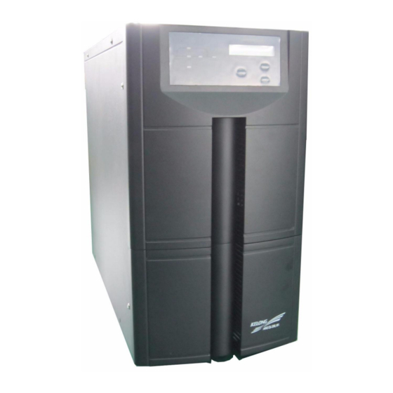
KR series(6-10kVA)user’s manual 3.3.4 KR6000, KR(/B)1110S, KR(/B)3110S appearance 3.3-5 KR6000, KR(/B)1110S, KR(/B)3110S appearance - 17 -... -
Page 21: Front Panel
BATTERY BYPASS Breaker BYPASS Breaker POWER Breaker POWER Breaker BATTERY Breaker BATTERY Breaker LINE BAR LINE BAR COVER COVER Front panel KR6000 rear panel KR(/B)1110S, KR(/B)3110S rear panel 3.3-6 KR6000, KR(/B)1110S, KR(/B)3110S Front Panel and Rear Panel - 18 -... -
Page 22: Installation
KR series(6-10kVA)user’s manual 4. Installation Summary The chapter introduces notice, flow and installation steps Installation Notice 1. Before installing UPS, check if the feeding circuit of grid is clear, including contacts of all the connection points as well as sockets are OK, so as to avoid open circuit or short circuit. 2.... -
Page 23: Installation Process
KR series(6-10kVA)user’s manual ◆ If UPS are placed at location under 0℃ too long, please turn on the UPS before temperature above 0℃ for more than 2 Hours. Installation process Installation process for KR Series (6&10kVA),please see Fig.4.2-1 Fig.4.2-1 installation chart for UPS system ... - Page 24 KR series(6-10kVA)user’s manual Altitude: meet GB/T 7260.3-2003; Verticality: no shock with orthogonal rake not exceeding 5; Pollution rank: Class Ⅱ ; The UPS should be installed in the environment where exists enough ventilation, coolness, not too high temperature and without dust. The recommended work temperature is 20~25℃ and the humidity should be controlled around 50%.
-
Page 25: Unpacking And Inspect The Machine
KR series(6-10kVA)user’s manual Table 4.3-2 Recommended Conductor sectional of UPS (mm KR6kVA KR10kVA AC INPUT(Live and Zero line) AC INPUT(G) DC INPUT ( Positive and Negative ) OUTPUT(Live and Zero line) Cross-sectional area of cable mentioned above is only suitable for 5 meters cable. If length of lead is longer than 20 meters, the Cross-sectional area of cable must be enlarged accordingly. -
Page 26: Machine Installation
If any doubt, please negotiate the solution with the local mains supply department. 4.6 UPS Installation 4.6.1 KR (6&10kVA) Series UPS installation Remove the UPS from bracket to ground for installation. Following are installation examples for KR6000. - 23 -... - Page 27 KR series(6-10kVA)user’s manual 1. after unpacking KR6000, the external structure as below: Fig 4.6 -1 Installation steps 1 2、Loosen and take down 6 pieces of Hexagon bolt M8×20 ( Two on both left and right side) between Anchor frame and tail margin supporting plates.
-
Page 28: Battery Cabinet Installation
KR series(6-10kVA)user’s manual 3.Move UPS from Flat Pallets to ground, as following: Fig 4.6 -3 Installation steps 3 4.7 Battery Cabinet Installation For long back up time UPS, besides mainframe, also equip batteries and battery cabinet, 4.7.1Important Security Regulation Do not unclench or detach battery, because it would result in injury to person skin and eye by electrolyte inside them. -
Page 29: Parallel)System Installation
KR series(6-10kVA)user’s manual 2. Under the status that the AC input is normal and UPS has no load, turn on the main switch of UPS to measure the DC voltage of external battery connection. 3. If the result, gained from step 2, called charge voltage is normal, then connect the external battery group to UPS. -
Page 30: Wire Connection Of Parallel System
DC input("+") AC Output "L" 192VDC Grounding AC Output "N" DC input("-") AC Input "L" AC Input "N" Fig 4.9-1 KR6000(L)、 KR(/B)1110(S) Connection methods of line bar OUTPUT INPUT BATTERY AC Output "L" (240VDC) Grounding AC Output "N" AC Input "W"... - Page 31 KR series(6-10kVA)user’s manual 2. Connect all the system cells’ parallel connecters with Shielded communication cables, then lock RS232 Ports’ screws. 3. Parallel Connection for KR/B 1110(S) is demonstrated as in below figure 4.9-3. 4. Parallel Connection for KR/B 3110(S) is demonstrated as in below figure 4.9-4. BATTERY+ BATTERY- AC Input "L"...
- Page 32 KR series(6-10kVA)user’s manual BATTERY+ BATTERY- AC Input "W" AC Input "V" AC Input "U" AC Input "N" AC OUTPUT "L" BATTERY+ BATTERY- AC OUTPUT "N" AC Input "W" AC Input "V" AC Input "U" AC Input "N" Fig 4.9-4 Parallel connection procedures for KR/B3110(S) - 29 -...
-
Page 33: System Inspection And Testing
KR series(6-10kVA)user’s manual 4.10 System inspection and testing 4.10.1 Check electrical connections After electric connection, it’s required to check below items for electric connection results following below instructions in below list. Table 4.10-1 electric connection results examination sequence Examination Items Results yes□... -
Page 34: Using And Operation
KR series(6-10kVA)user’s manual 5. Using and Operation Summary Operation steps and methods are introduced in this chapter, including preparation before electrifying, UPS start steps when main source is normal, as well as UPS start steps and indicator light meaning when main source fail. 5.1 Notes of using UPS 1. -
Page 35: Operation Instruction
KR series(6-10kVA)user’s manual Fig. 5-2.1 single unit operation Steps for KR series(6&10Kva) 5.3 Operation instruction 5.3.1 Inspection before power on Before electrifying for the UPS, please check following below requirements. Only when confirm all is in good condition, the UPS can be started. 1. -
Page 36: Ups Startup Steps
KR series(6-10kVA)user’s manual 5. Make sure the computer and other devices are power off. 5.3.2 UPS Startup Steps Electrifying: Turn the power switch “ON” on the real panel as per below sequence. POWER→BATTERY Start Up: press “On” key on the panel and startup inverter Before UPS work stably, the automatic bypass will supply power to the load. -
Page 37: Operation Of Parallel System
KR series(6-10kVA)user’s manual 5.4. Operation of Parallel system 5.4.1 Parallel System start up Please keep load off before Parallel System starting up, and make sure all the breakers are off. Startup steps as following: 1. After confirming correct installation, start parallel units in turns as per UPS start steps. -
Page 38: Online Start-Up Parallel System
KR series(6-10kVA)user’s manual Picture 5.4-1 online drop out Parallel Unit Caution: When the parallel system is working normally, it is better not to quit its output from parallel system without shutting down parallel unit, otherwise the power system will appear abnormal. 5.4.4 Online start-up Parallel System When online launching one or more parallel unit is needed, just follow the operation steps on Fig.5.4-2 After the new unit is operating stably, it will enter... - Page 39 KR series(6-10kVA)user’s manual 2. Expansion Function Theoretically, UPS parallel has no quantity limitation. However if the quantity is over many, the reliability of the whole parallel system will decrease on the contrary, and can not reach the aim of improving reliability. Therefore, we don’t suggest using parallel mode to extend gross output power.
-
Page 40: Maintenance And Fault Diagnosis
KR series(6-10kVA)user’s manual 6. Maintenance and Fault Diagnosis Summary This chapter describes the maintenance guide, battery daily maintenance, battery replacement precautions and fault diagnosis. 6.1 Maintenance Guide Proper maintenance is the key to enable that the device can run in the best and with a longer service life 6.1.1 Safety Precaution Pay attention to the following safety operation regulations:... -
Page 41: Battery Daily Maintenance
KR series(6-10kVA)user’s manual 6.2 Battery Daily Maintenance 1. Battery charging notice 1) Using for the first time, switch to charge the battery for 4 h. During charging, it can still use UPS. But if the power fails at the same time, this time the battery discharge time may be shorter than the standard value. -
Page 42: Fault Diagnosis
KR series(6-10kVA)user’s manual 5. Replace the used battery with new ones that are of same capacity same type and same manufacturer. It is strictly prohibit to use the battery with different capacity, type and manufacturers. 6. Dangerous voltage may exist between battery terminal and the ground. Test before touching. - Page 43 KR series(6-10kVA)user’s manual Abnormal situation Possible cause [problem 5] UPS works properly after It is normal phenomenon that in Battery inversion status, the start-up, and automatically shuts off system auto power-off caused by protection of battery after a certain period of time. low-voltage when battery used up.
-
Page 44: Troubleshooting For The Failure Of Single Units System And Parallel System
KR series(6-10kVA)user’s manual 6.4.2 Troubleshooting for the failure of single units system and parallel system 1. How to deal with the failure in single units system When single units system is failure, cut off the power by “OFF” button on the UPS panel. -
Page 45: Appendix A. Packaging Transportation And Storage
Appendix A. Packaging Transportation and Storage Packaging Packed by carton, pay attendtion to the requirement of the layed direction of each part. The side of the carton should be with the warming mark of no humid, handle with care, upwards, max number of stacking and etc., also with the model information. -
Page 46: Appendix B Table Of Toxic And Harmful Substance In Product
Appendix B Table of Toxic and harmful substance in product Declare the Toxic and harmful substance Component PBDE ○ ○ ○ ○ ○ ○ Cabinet ○ ○ ○ Terminal, socket connector, × × × wire chase ○ ○ Breaker, relay ×... - Page 47 ③ Some elements of the stock plastic material don’t reach the standard, now they are under changing - 44 -...
Need help?
Do you have a question about the KR6000 and is the answer not in the manual?
Questions and answers