Table of Contents
Advertisement
OPERATION AND INSTALLATION
FUNCIONAMIENTO E INSTALACIÓN
MODE D'EMPLOI ET INSTALLATION
DHW heat pump water heater
Calentador de agua con bomba eléctrica de calor
Chauffe-eau à thermopompe
» Accelera 220 E
» Accelera 300 E
Conforms to ANSI/UL Std. 499, 1995, 94-5 VA, 174
Certifi ed to CAN/CSA Std. C22.2 No. 110
Conforme a ANSI/UL Std. 499, 1995, 94-5 VA, 174
Certifi cación con CAN/CSA Std. C22.2 No. 110
Conforme à la norme ANSI/UL Std. 499, 1995, 94-5 VA, 174
Certifi é à la norme CAN/CSA Std. C22.2 No. 110
Tested and certifi ed by WQA to NSF/ANSI 372
for lead free compliance.
Probado y certifi cado por WQA NSF/ANSI 372 para
el cumplimiento de las regulaciones sin plomo.
Testé et certifi é par WQA à la NSF/ANSI 372 pour
une utilisation sans plomb.
Advertisement
Table of Contents
Troubleshooting

Related Manuals for STIEBEL ELTRON Accelera 220 E


Summary of Contents for STIEBEL ELTRON Accelera 220 E
- Page 1 DHW heat pump water heater Calentador de agua con bomba eléctrica de calor Chauffe-eau à thermopompe » Accelera 220 E » Accelera 300 E Conforms to ANSI/UL Std. 499, 1995, 94-5 VA, 174 Certifi ed to CAN/CSA Std. C22.2 No. 110 Conforme a ANSI/UL Std.
-
Page 2: Table Of Contents
CONTENTS ® ACCELERA 220 E QUICK START-UP GUIDE Shutting down ______________________________________________ 22 Troubleshooting ____________________________________________ 22 OPERATION 13.1 Fault table ________________________________________________________ 23 General information _________________________________________7 13.2 Resetting the safety pressure limiter _______________________ 23 Safety __________________________________________________________7 13.3 Resetting the high limit safety cut-out _____________________ 23 Intended use ______________________________________________________ 7 13.4 Motor overload relay ___________________________________________ 23... - Page 3 - Installation of water heater by unqualifi ed personnel 1 Serial number on the type plate - Unauthorized modifi cations Type, Example: Accelera 220 E (the type plate can be found - Use of unauthorized spare parts on the appliance above the “DHW outlet” connection).
-
Page 4: Accelera 220 E Quick Start-Up Guide
QUICK START-UP GUIDE General information ACCELERA® 220 E QUICK START-UP GUIDE Overview: Installation of this water heater is similar to standard electric water heaters, with a few minor exceptions. Be sure to follow all state and local codes during installation. This Quick Start-up Guide is not intended to be a substitute for the complete installation manual. Be sure to follow all safety precautions. - Page 5 QUICK START-UP GUIDE Required room dimensions and clearances › Do not install in a room with less than 800 cubic Minimum room volume: 14˝ feet of total volume. 800 ft , 10´ x 10´ x 8´ (0.4 m) › Do not install with the air (22.7 m , 3 m x 3 m x 2.4 m) Air flow...
-
Page 6: Plumbing Connections
QUICK START-UP GUIDE Plumbing connections Cold water Hot water Vacuum breaker Hot water connection (1˝ NPT) Mixing valve (optional, supplied by installer) Connection for T&P valve (¾˝ NPT) T&P valve ¾˝ NPT, 0.69 MPa @ 99°C (100 psi @ 210°F) (supplied with unit) Expansion tank (required, supplied by installer) Straight-through shut-off valve (supplied by installer) Check valve (required, supplied by installer) -
Page 7: General Information
OPERATION General information OPERATION WARNING Electrocution Contact with live components presents a threat to life. Damage to the electric insulation or to individual com- ponents may result in a threat to life. If there is damage to the insulation, disconnect the ... -
Page 8: Etl Designation
CAUTION Hydrogen gas is produced by this heater in a hot water 1. Type plate label for the Accelera 220 E system that has not been used for a long period of time (2 weeks or more). Hydrogen gas is extremely fl amma- No.:#### / ######... - Page 9 OPERATION Safety 6. Scald risk information label 7. Gasket connection information label For reason of corrosion protection use flat gasket ring. Never seal threadshemp (equipment Damage!). AQUA CALIENTE Para la protección contra la corrosión use sellos planos de los tubos. Una unión con cáñamo no está...
-
Page 10: Appliance Description
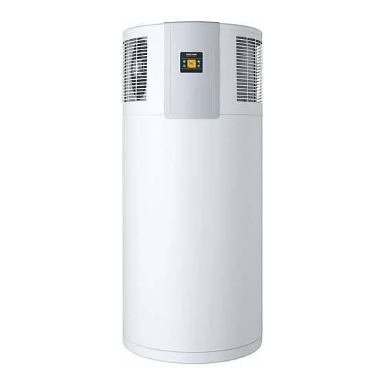
OPERATION Appliance description 11. Booster heater element information label Appliance description The appliance is designed for indoor installation. The appliance CAUTION recirculates ambient air and does not require outdoor air. The for use only in water appliance extracts heat from the ambient air. This heat is utilized ATTENTION to heat the water in the DHW tank with added electric power. -
Page 11: Heating The Dhw Tank
OPERATION Appliance description Heating the DHW tank Appliance operation outside the application limits 3.2.1 Ambient temperatures below the application limit If hoar frost is growing on the evaporator fi ns, the hoar frost temperature monitor switches the heat pump compressor off. The compressor switches on automatically once the evaporator defrosts. -
Page 12: Settings
OPERATION Settings Settings Note 15 seconds after every adjustment, the appliance auto- Display and controls matically switches back to the standard display and saves the set value. Note The back-light of the display will illuminate for 15 seconds With the menu key, all information and after pressing any button. -
Page 13: Calling Up Fault Codes
OPERATION Settings If the relevant set DHW temperature is accomplished, the com- Adjust set temperature 1 from 69 to pressor switches off and remains off for a minimum idle time of 149°F / 20.5 to 65°C using the plus and 20 minutes. minus keys. -
Page 14: Emergency Shutdown
OPERATION Maintenance and care The heat pump remains on and the comfort heating function re- Emergency shutdown mains active until a temperature of 149°F/65°C) has been achieved In the event of an emergency, carry out the following steps: in the entire DHW tank (comfort heating). The appliance then au- ... -
Page 15: Troubleshooting
OPERATION Troubleshooting Troubleshooting Problem Cause Remedy Service symbol See 6.1, “Fault codes”, It is imperative that you notify Problem Cause Remedy flashes and the pg. 16 a qualified contractor. water does not No hot water is No power to the appli- Check that the appliance heat up. -
Page 16: Fault Codes
8+2+16+128 No fault 8+4+16+128 continu- The dome sensor has failed. Call Stiebel Eltron for ously illu- The temperature displayed is more information if minated measured by the integral sen- this error occurs. When the appliance is operating in emergency backup mode, the sor. -
Page 17: Installation
INSTALLATION Safety INSTALLATION 7.4.4 Customer service For customer service inquiries, please contact Stiebel Eltron di- rectly at 1-800-582-8423 Safety Appliance description Only a qualifi ed contractor should carry out the installation, com- The heat pump unit is located in the upper section of the appliance. -
Page 18: Storage
INSTALLATION Preparations Vehicular transport - The installation room must be free from the risk of frost. - The intake temperature of the appliance must be within the Material losses permissible application limits (See 15.3, “Data table”, pg. Storing and transporting the appliance vertically is rec- 29). -
Page 19: Siting The Appliance
INSTALLATION Preparations Siting the appliance Minimum clearances Carefully undo the cardboard packaging at the clips. Minimum room volume: 14˝ 800 ft , 10´ x 10´ x 8´ (0.4 m) (22.7 m , 3 m x 3 m x 2.4 m) Air flow intake Air flow... -
Page 20: Installation
INSTALLATION Installation 10.1.2 Pressure reducing valve 10. Installation Note WARNING Injury A 70 psi (4.8 bar) pressure reducing valve must be in- Incorrect installation can lead to serious personal injury stalled to ensure the pressure of the incoming water line or material losses. - Page 21 For an original EVU: L1, L2 oder L3 spare part contact Stiebel Eltron 800-582-8423 for part number 315650. Example 2: Photo-voltaic signal via on-site relay and phase routed outside the appliance...
-
Page 22: Assembling The Appliance
INSTALLATION Commissioning Connect the leads to X0 (see chapter "See 10.3.1, “Connection Make users aware of potential dangers, especially the risk of with external signal transmitter”, pg. 21). scalding. Make users aware of critical environmental factors and re- ... -
Page 23: Fault Table
INSTALLATION Maintenance and cleaning 13.1 Fault table 13.4 Motor overload relay In the event of excessive thermal load of the compressor, the motor Fault Cause Remedy overload relay switches the compressor off. The appliance Excessive pressure in Eliminate the cause of the in- ... -
Page 24: Removing The Casing Ring
INSTALLATION Maintenance and cleaning 14.2 Removing the casing ring 14.3 Cleaning the evaporator WARNING Injury Note The evaporator consists of numerous sharp-edged fi ns. If you require more space to work inside the appliance, Be careful during cleaning the evaporator and wear pro- you can remove the casing on the upper section of the tective clothing, especially safety gloves. -
Page 25: Descaling The Electric Booster Element
INSTALLATION Maintenance and cleaning 14.5 Descaling the electric booster element 14.9 Fitting the casing ring Only descale the fl ange of the electric booster element after re- WARNING Electrocution moving it, and never treat the interior of the DHW tank and the im- ... -
Page 26: Specifi Cation
INSTALLATION Specifi cation 15. Specifi cation 15.1 Dimensions and connections ® 15.1.1 Accelera 220 E ˝ (690 mm) ˝ (1545 mm) ˝ (1160 mm) ˝ (884 mm) ˝ ˝ – (241 mm) (8–24 mm) Accelera® 220 E Entry electrical cables Cold water inlet Male thread 1˝... - Page 27 INSTALLATION Specifi cation ® 15.1.2 Accelera 300 E ˝ (690 mm) ˝ (1913 mm) ˝ (1528 mm) ˝ (1252 mm) ˝ ˝ – (241 mm) (8–24 mm) Accelera® 300 E Entry electrical cables Cold water inlet Male thread 1˝ NPT DHW outlet Male thread 1˝...
-
Page 28: Wiring Diagram
INSTALLATION Specifi cation 15.2 Wiring diagram Passive defrost / active anode storage tank bn bu bn bk storage tank outer jacket gnye bk 1 bk 2 Electronic assembly (control unit) Electronic assembly (programming unit) Temperature sensor Capacitor Heating element (1.5 kW) High limit safety cut-out TSR (189 °F ±8 / 87 °C ±5 Motor overload relay M1 High pressure switch (348 psi / 24 bar) -
Page 29: Data Table
INSTALLATION Specifi cation 15.3 Data table Accelera® 220 E Accelera® 300 E 233058 233059 Hydraulic data Nominal capacity 58 gal / 220 l 79.8 gal / 302 l Application limits Maximum DHW temperature 149 °F / 65 °C 149 °F / 65 °C Heat source min./max. -
Page 30: Limited Warranty
This Warranty is valid for U.S.A. & Canada only. Warranties Refrigerant R134a is a CFC greenhouse gas mentioned in the 413.247.3369 may vary by country. Please consult your local Stiebel Eltron Kyoto protocol with a global greenhouse potential (GWP) = 1300. info stiebel-eltron-usa.com... - Page 31 STIEBEL ELTRON, Inc. 17 West Street | West Hatfield MA Tel. 0413 247-3380 | Fax 0413 247-3369 info@stiebel-eltron-usa.com www.stiebel-eltron-usa.com 4 < A M H C M O = b c a j h b > Due to our continuous process of engineering and technological Stand 8643 advancement, specifications may change without notice.
Need help?
Do you have a question about the Accelera 220 E and is the answer not in the manual?
Questions and answers