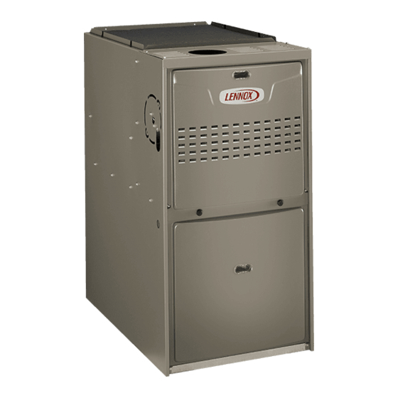
Lennox ML180UH Merit Series Installation Instructions Manual
Gas furnace
upflow / horizontal air discharge
Hide thumbs
Also See for ML180UH Merit Series:
- Installation instructions manual (43 pages) ,
- User's information manual (8 pages) ,
- Manual (33 pages)
Table of Contents
Advertisement
E 2015 Lennox Industries Inc.
Dallas, Texas, USA
AIR FLOW
HORIZONTAL LEFT
. . . . . . . . . . . . . . . . . . . . . . . . . . . . . . . .
. . . . . . . . . . . . . . . . . . . . . . . . . .
. . . . . . . . . . . . . . . . . . . . . . . . . . . . . . .
. . . . . . . . . . . . . . . . . . . . . . . . . . . . . . . . . . . . . . . .
. . . . . . . . . . . . . . . . . . . . . . . . . . . . . . .
. . . . . . . . . . . . . . . . . . . . . . . . . . . . . . . . . . . . . . . . . .
. . . . . . . . . . . . . . . . . . . . . . . . . . . . . . . . . . . .
. . . . . . . . . . . . . . . . . . . . . . . . . . . . . . . . . . . . . . . .
UPFLOW
HORIZONTAL RIGHT
Table of Contents
. . . . . . . . . . . . . . . . . . . . . . . .
. . . . . . . . . . .
. . . . . . . . . . . . . .
INSTALLATION
INSTRUCTIONS
ML180UH
®
MERIT
SERIES GAS FURNACE
UPFLOW / HORIZONTAL AIR DISCHARGE
507323-01
06/2015
Supersedes 507009-01
THIS MANUAL MUST BE LEFT WITH THE
HOMEOWNER FOR FUTURE REFERENCE
This is a safety alert symbol and should never be ignored.
When you see this symbol on labels or in manuals, be alert
to the potential for personal injury or death.
Improper installation, adjustment, alteration, service
or maintenance can cause property damage, person
al injury or loss of life. Installation and service must
be performed by a licensed professional HVAC in
staller (or equivalent), service agency or the gas sup
plier.
As with any mechanical equipment, personal injury
can result from contact with sharp sheet metal
edges. Be careful when you handle this equipment.
2
. . . . . . . . . . . . . . . . . . . . . . . . . . . . . . . . . . . . .
3
. . . . . . . . . . . . . . . . . . . . . . . . . . . . . . . . . . . . . . .
3
3
. . . . . . . . . . . . . . . . . . . . . . . . . . . . . . . . . . .
4
4
. . . . . . . . . . . . . . . . . . . . . . . . . . . . . . . . . . . .
5
8
11
12
. . . . . . . . . . . . . . . . . . . . . . . . . . . . . . . . . . . . . . . .
13
. . . . . . . . . . . . . . . . . . . . . . . . . . . . . . . . . . . .
Page 1
WARNING
. . . . . . . . . . . . . . . . . . . . . . . . . . . . . . .
. . . . . . . . . . . . . . . . . . . . . . . .
. . . . . . . . . . . . . . . . . . . . . . . . . . . . . .
. . . . . . . . . . . . . . . . . . . . . . . . . .
. . . . . . . . . . . . . . . . . . . . . . . . . .
Litho U.S.A.
20
22
24
26
26
26
26
28
29
30
32
Advertisement
Table of Contents

Related Manuals for Lennox ML180UH Merit Series


Summary of Contents for Lennox ML180UH Merit Series
-
Page 1: Table Of Contents
INSTALLATION INSTRUCTIONS E 2015 Lennox Industries Inc. Dallas, Texas, USA ML180UH ® MERIT SERIES GAS FURNACE UPFLOW / HORIZONTAL AIR DISCHARGE 507323-01 06/2015 Supersedes 507009-01 Litho U.S.A. THIS MANUAL MUST BE LEFT WITH THE HOMEOWNER FOR FUTURE REFERENCE This is a safety alert symbol and should never be ignored. -
Page 2: Unit Dimensions
Unit Dimensions - inches (mm) NOTE - 60C and 60D units that require air volumes 3−1/8 (79) over 1800 cfm (850 L/s) must have one of the following: 1. Single side return air with transition to accommodate 20 x 25 x 1 in. (508 x 635 x 25 mm) cleanable air filter. -
Page 3: Ml180Uh Gas Furnace
ML180UH Gas Furnace CAUTION The ML180UH unit is shipped ready for installation in the As with any mechanical equipment, personal injury upflow or horizontal right position (for horizontal left posi can result from contact with sharp sheet metal edges. Be careful when you handle this equipment. tion the combustion air pressure switch must be moved). -
Page 4: Use Of Furnace As A Construction Heater
Lennox does not recommend the use of ML180UH units as the full HEAT or COOL setting. See figure 1. -
Page 5: General
will build to the point that a downdraft can occur in the fur General nace vent pipe or chimney. As a result, combustion gases enter the living space creating a potentially dangerous situ These instructions are intended as a general guide and do ation. - Page 6 In addition to providing combustion air, fresh outdoor air di EQUIPMENT IN CONFINED lutes contaminants in the indoor air. These contaminants SPACE ALL AIR FROM INSIDE may include bleaches, adhesives, detergents, solvents CHIMNEY OR GAS and other contaminants which can corrode furnace compo VENT nents.
- Page 7 When ducts are used, they shall be of the same cross-sec it may be assumed that wood louvers will have 20 to 25 per tional area as the free area of the openings to which they cent free area and metal louvers and grilles will have 60 to connect.
-
Page 8: Setting Equipment
Upflow Applications Setting Equipment Allow for clearances to combustible materials as indicated WARNING on the unit nameplate. Minimum clearances for closet or al cove installations are shown in figure 7. Do not install the furnace on its front or its back. Do Upflow Application Installation Clearances not connect the return air ducts to the back of the fur... - Page 9 Return Air -- Upflow Applications Single Side Return Air Return air can be brought in through the bottom or either (with transition and filter) side of the furnace installed in an upflow application. If the furnace is installed on a platform with bottom return, make an airtight seal between the bottom of the furnace and the platform to ensure that the furnace operates properly and safely.
- Page 10 Pivot the bottom cap down to release the bottom plications. Order horizontal suspension kit (51W10) from panel. Once the bottom panel has been removed, reinstall Lennox, or use equivalent suspension method. the bottom cap. See figure 10. Allow for clearances to combustible materials as indicated on the unit nameplate.
-
Page 11: Filters
Before using any filter with this system, check the SERVICE PLATFORM specifications provided by the filter manufacturer against the data given in the appropriate Lennox Product Specifications bulletin. Additional informa FIGURE 13 tion is provided in Service and Application Note ACC002 (August 2000). -
Page 12: Duct System
Return Air Plenum Duct System NOTE - Return air must not be drawn from a room Use industry‐approved standards (such as those pub where this furnace, or any other gas-fueled appliance lished by Air Conditioning Contractors of America or Ameri (i.e., water heater), or carbon monoxide producing de... -
Page 13: Venting
1 - Remove the four mounting screws (figure 14) which Venting secure the combustion air inducer / pressure switch A 4-inch diameter flue transition is factory‐installed on the assembly to the orifice plate. Lift the assembly and ro tate it 90 degrees clockwise or counterclockwise to ei combustion air inducer outlet of all models. - Page 14 HORIZONTAL RIGHT POSITION HORIZONTAL LEFT POSITION Top Vent Discharge Top Vent Discharge Vent Pipe Vent Pipe Pressure Switch Pressure Flue Switch Transitio Cover Plate Flue Transition FLOW FLOW Collector Box Make-Up Box Cover Plate Make-Up Box Collector Box D Disconnect pressure switch hose from barbed fitting on the D Gas supply piping must be brought into the unit from the bot...
- Page 15 The ML180UH series units are classified as fan-assisted Masonry chimneys used to vent Category I central fur naces must be either tile‐lined or lined with a listed metal Category I furnaces when vertically vented according to lining system or dedicated gas vent. Unlined masonry the latest edition of National Fuel Gas Code (NFPA 54 / chimneys are prohibited.
- Page 16 When inspection reveals that an existing chimney is not Common Venting Using Metal-Lined Masonry Chimney safe for the intended purpose, it shall be rebuilt to conform to nationally recognized standards, lined or relined with SEALED suitable materials, or replaced with a gas vent or chimney suitable for venting ML180UH series units.
- Page 17 Common Venting Using Tile-Lined Interior Masonry Chimney and Combined Vent Connector MINIMUM LENGTH = AS SHORT AS PRACTICAL. INTERIOR TILE-LINED FOR MAXIMUM LENGTH SEE NOTE TO LEFT MASONRY CHIMNEY NOTE- Refer to provided venting tables for installations. NOTE - the chimney must be properly sized per provided venting tables or lined with listed metal lining system.
- Page 18 16 - Vent connectors serving Category I appliances shall two consecutive table size diameters over the size of not be connected to any portion of mechanical draft the draft hood outlet or flue collar outlet. systems operating under positive pressure such as 20 - Do not install a manual damper, barometric draft regu...
- Page 19 TABLE 4 Vent Connector Capacity Type B Double-Wall Vents with Type B Double-Wall Connectors Serving Two or More Category I Appliances Vent and Connector Diameter - D (inches) Vent Connector 3 Inch 4 Inch 5 Inch 6 Inch Height Rise Appliance Input Rating in Thousands of Btu Per Hour (feet) (feet)
-
Page 20: Caution
Removal of the Furnace from Common Vent Resize the common venting system to the minimum vent pipe size determined by using the appropriate In the event that an existing furnace is removed from a tables in Appendix G. (These are in the current stan venting system commonly run with separate gas ap... - Page 21 TABLE 6 Gas Pipe Capacity - ft /hr (m /hr) Nominal Length of Pipe - feet (m) Internal Iron Pipe Diameter Size inches inches (mm) (3.048) (6.096) (9.144) (12.192) (15.240) (18.288) (21.336) (24.384) (27.432) (30.480) (mm) .622 (12.7) (17.799) (4.87) (3.34) (2.69) (2.29)
-
Page 22: Electrical
Leak Check The unit is equipped with a field make-up box on the left hand side of the cabinet. The make-up box may be moved After gas piping is completed, carefully check all piping to the right side of the furnace to facilitate installation. If the connections (factory- and field-installed) for gas leaks. - Page 23 ing. Any humidifier rated up to one amp can be connected WARNING to this terminal with the neutral leg of the circuit being con nected to one of the provided neutral terminals. If a humidi Fire Hazard. Use of aluminum wire with this product fier rated at greater than one amp is connected to this termi...
-
Page 24: Integrated Control
Integrated Control INTEGRATED CONTROL (Automatic Hot Surface Ignition System) TERMINAL DESIGNATIONS Humidifier (120VAC) Input (120VAC) LINE Transformer (120VAC) XFMR Indoor Air Qality Accessory Air Cleaner (120VAC) Blower - Cooling Speed (120VAC) COOL Blower - Heating Speed (120VAC) HEAT Dead terminals to park alternate spd taps PARK Continuous blower CONT... - Page 25 ML180UH Schematic Wiring Diagram and Sequence of Operation FIGURE 30 Page 25...
-
Page 26: Unit Start-Up
6 - Move switch on gas valve to OFF. Do not force. See Unit Start-Up figure 31. FOR YOUR SAFETY READ BEFORE LIGHTING 7 - Wait five minutes to clear out any gas. If you then smell gas, STOP! Immediately call your gas supplier from a WARNING neighbor's phone. -
Page 27: High Altitude
Heating Sequence Of Operation access to the supply pressure tap. Remove the threaded plug, install a field-provided barbed fitting and connect a (follow steps below or see Figure 30 for more detail) manometer to measure supply pressure. See table 9 for 1 - When thermostat calls for heat, combustion air blower proper line pressure. -
Page 28: Other Unit Adjustments
TABLE 9 Manifold Pressure Settings at all Altitudes Line Pressure in.wg. Model 0-2000 ft 2001-4500 ft. 4501-7500 ft 7501 - 10,000 ft Input Size 13.0 LP/propane 10.0 10.0 10.0 10.0 11.0 13.0 13.0 LP/propane 10.0 10.0 10.0 10.0 11.0 13.0 13.0 LP/propane 10.0... -
Page 29: Twinning The Ml180Uh
Twinning 2 ML180UH Furnaces The 24 VAC secondary of the two systems must be in The control board in this furnace is equipped with a provi phase. All thermostat connections are made to one control sion to ”twin” (interconnect) two(2) adjacent furnaces with a only. -
Page 30: Service
Unit Nameplate__________Actual__________ At the beginning of each heating season, and to comply Blower Speeds with the Lennox Limited Warranty, your system should Follow the steps below to change the blower speeds. be checked by a licensed professional technician (or equiv... - Page 31 9- Ensure sufficient combustion air is available to the fur Manual for proper operating range. Thermal Limits should be checked by restricting airflow and not dis nace. Fresh air grilles and louvers (on the unit and in the connecting the indoor blower. For additional details, room where the furnace is installed) must be properly please see Service and Application Note H049.
-
Page 32: Repair Parts
FIGURE 34 Repair Parts List The following repair parts are available through independent Lennox dealers. When ordering parts, include the complete furnace model number listed on the CSA International nameplate -- Example: ML180UH045P24A-01. All service must be performed by a licensed professional installer (or equivalent), service agency, or gas supplier.
Need help?
Do you have a question about the ML180UH Merit Series and is the answer not in the manual?
Questions and answers