Table of Contents
Advertisement
Advertisement
Table of Contents

Related Manuals for Jands HPC AIRGAP


Summary of Contents for Jands HPC AIRGAP
- Page 2 JANDS PTY LTD shall not be liable for any loss or damage whatsoever arising from the use of information or any error contained in this manual. It is recommended that all service and repairs on this product be carried out by JANDS PTY LTD or its authorised service agents.
-
Page 3: Table Of Contents
About This Manual Table of Contents Table of Contents ...................... 2 About This Manual ..................3 Important Safety Information ................... 3 Introduction ..................... 4 Features ........................4 Equipment Description ..................5 Front Panel Layout ..................... 5 Getting Started ....................6 Connecting Power ...................... -
Page 4: About This Manual
About This Manual Ventilation ....................... 16 Supply Wiring ......................16 Maintenance ....................17 External Cleaning ..................... 17 Internal Cleaning ...................... 17 Routine Maintenance ....................17 Technical Data and Specifications ..............18 DMX Connector Pinouts ..................19 RDM Implementation ....................19 9.2.1 Root Device PIDs .................... -
Page 5: Introduction
Introduction 2.0 Introduction The HPC is a professional power control product designed primarily for use in performance spaces, but has many additional applications. Each of the 12 channels incorporates a full power dimmer circuit and two high current relays connected as shown in Figure 1. -
Page 6: Equipment Description
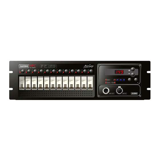
Equipment Description 3.0 Equipment Description Front Panel Layout Refer to Figure 2 for a description of the front panel controls. 6, 7, 8, 9 (REAR) 11, 12 Figure 2: HPC front panel layout Channel output sockets (rear panel): The output sockets are located on the back panel. -
Page 7: Getting Started
Getting Started 4.0 Getting Started The HPC would normally be rack mounted before any wiring is terminated. Refer to Section 6.0 Installation for installation details. Connecting Power The HPC dimmer may be supplied with a mains inlet cable and multipin connector, mains inlet cable and no connector, or with no inlet cable fitted. -
Page 8: Connecting Control Input
Getting Started 1. Press the Channel Switch for the channel to be reconfigured. All of the Channel LEDs now flash to indicate the current mode of operation as shown in Table 1. 2. Continue to press the channel Switch until the required function is indicated by the LED/s. -
Page 9: Operation
Dimmer Operation 5.0 Operation This section assumes the HPC has been correctly connected to the mains power supply and a source of DMX-512 control signal. Menu and Setting Adjustment • Pressing MENU/ at any time moves up a menu level or confirms a new setting. •... - Page 10 DMX Address Test Channel Select Channel Use Channel Select buttons to activate channels Sets NE fault Change DMX ~ * NE Protection NE Protection ~ * detector on or off Hold Output Sets dimmer to hold data when DMX is lost ...
- Page 11 Dimmer Operation First Second Third Description Level Level Level Use channel select buttons drive channel/s to full On-off When ON the N-E fault detector is enabled no.S Set the HPC to hold the current output upon loss of DMX data no.S Sc.1 Set the HPC to fade to Scene 1 upon loss of DMX...
-
Page 12: Cap Function
Dimmer Operation 5.1.2 Cap Function The Cap function is used to scale the output voltage of all channels from the maximum of 240V. This may be used to extend lamp life or allows other voltage loads to be run, such as 230V or 120V lamps. Note that the Cap level may be individually set for a channel by selecting that channels “Mode”... -
Page 13: Automatic Relay Control - Bypass Relay
Dimmer Operation Display Setting Channel Level Data RDM Control Data is received on: received on: Front panel DMX connector Front panel DMX connector Front panel DMX connector Ethernet Option connector Ethernet Option connector Front panel DMX connector Ethernet Option connector Ethernet Option connector 5.1.7 Automatic Relay Control –... -
Page 14: Rdm Facility
Dimmer Operation 5.3 RDM Facility RDM is a specification for a protocol that enables a RDM “controller” to set and alter parameters within a RDM “device” via the DMX-512 connection. An RDM system consists of one RDM controller and at least one RDM device. The HPC is an RDM device. -
Page 15: Fault Diagnosis
6.0 Fault Diagnosis NOTE Contact your authorised JANDS Distributor for repairs or servicing. In Australia refer all repairs to an authorised JANDS service agent or return the faulty unit in suitable packaging to: JANDS PTY LTD Service Dept, 2-26 Kent Rd... -
Page 16: Fault Finding Guide
Fault Diagnosis 6.4 Fault Finding Guide FAULT SYMPTOM POSSIBLE CAUSE REMEDY Breaker trips Excessive load Reduce channel loading Lamp or wiring fault Check lamps and wiring Poor ventilation Increase air flow to HPC side vents Faulty HPC Service HPC One channel flickers when dimmed DMX source problem Softpatch another console fader Service console... -
Page 17: Installation
Installation 7.0 Installation The HPC is designed for use in 19 inch racks or a 19 inch bar frame, and occupies 3 or 4 rack units. The HPC is supplied with rear rack mounting support brackets, which provide additional support for touring applications. The mains supply power cable entry is located at the rear right side of the rack when viewed from the front. -
Page 18: Maintenance
Maintenance 8.0 Maintenance With care, the HPC will require little or no maintenance. However periodic electrical safety checks may be required by law in some countries. External Cleaning If the front panel requires cleaning, wipe with a mild detergent on a damp soft cloth. DO NOT allow liquids into the chassis. -
Page 19: Technical Data And Specifications
Technical Data and Specifications Technical Data and Specifications PARAMETER SPECIFICATION Active-Neutral Supply Voltage 100-230VAC ±10% Full size neutral required Supply Frequency 40-66Hz Supply Protection 10K Amps Rated Insulation Voltage 430VAC Phase to Phase, 250VAC Phase to Neutral Rated Output Current 10 Amps per channel Minimum Power/Channel Maximum Dissipation... -
Page 20: Dmx Connector Pinouts
Technical Data and Specifications DMX Connector Pinouts CONNECTION CONNECTION (DMX IN) (LOOP) SHIELD SHIELD OUT- OUT+ DMX Loop pin 4 DMX In pin 4 DMX Loop pin 5 DMX In pin 5 RDM Implementation 9.2.1 Root Device PIDs Notes DISC_UNIQUE_BRANCH ... - Page 21 Technical Data and Specifications SENSOR_DEFINITION 4: Temperature, Frequency, DMX rate, Phases SENSOR_VALUE IDENTIFY_DEVICE Animates display. Will time out RESET_DEVICE 0x01 & 0xFF – Result in warm reset CAPTURE_PRESET Scenes 1,2 Preset 0x0001, 0x0002 ...
-
Page 22: Sub Device Pids
Technical Data and Specifications 9.2.2 Sub Device PIDs One sub device per HPC channel (12 total) Notes SUPPORTED_PARAMETERS DEVICE_MODEL_DESCRIPTION Up to firmware rev 2.12: Channel dependant From firmware rev 2.13: Same for all sub-devices MANUFACTURER_LABEL Same as root ...
Need help?
Do you have a question about the HPC AIRGAP and is the answer not in the manual?
Questions and answers