
Related Manuals for Alto FLEX plus


Summary of Contents for Alto FLEX plus
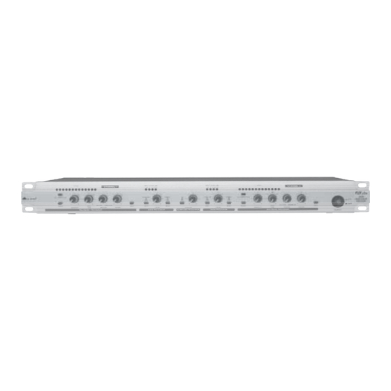
- Page 1 User's Manual FLEX plus SOUND ENHANCEMENT PROCESSOR www.altoproaudio.com Version 1.0 November 2003 English...
- Page 2 the recommended fuse type as indicated in this SAFETY RELATED SYMBOLS manual. Do not short-circuit the fuse holder. Before replacing the fuse, make sure that the product is CAUTION OFF and disconnected from the AC outlet. RISK OF ELECTRIC SHOCK DO NOT OPEN Protective Ground This symbol, wherever used, alerts you to the pre-...
- Page 3 Nothing else to add, but that we would like to thank all the people that made the FLEX plus a reality available to our customers, and thank our designers and all the...
-
Page 4: Table Of Contents
TABLE OF CONTENTS 1. INTRODUCTION............................4 2. FEATURE LIST............................4 3. CONTROL ELEMENTS..........................4 3.1 The Front Panel 3.1.1 MULTIBAND PROCESSOR Section 3.1.2 BASS PROCESSOR Section 3.1.3 SURROUND PROCESSOR Section 3.2 The Rear Panel 4. INSTALLATION AND CONNECTION.......................7 4.1 Mains Connection 4.2 Audio Connection 4.3 Rack Mounting 5. -
Page 5: Introduction
The FLEX plus is able to provide better stereo effect and increase the transparency and presence of sound. It can precisely modify the bass "contour" for more lively and natural sound. For more detailed information, please read this manual carefully. -
Page 6: Multiband Processor Section
Engage this switch to activate the auto reduction function, which is used to reduce the undesired noise in the system. If releasing the switch, the auto reduction function will have no any effect on the unit, then the FLEX plus works under the maximum effect, and all EFFECT LEDs will light up. 6. SENSITIVITY Control In order to achieve the proper effect, you can rotate this control to adjust the sensitivity for input signal depending on the EFFECT LED display. -
Page 7: Surround Processor Section
11. SHIFT Switch Through this switch to select the cutoff frequency for low pass filter (or high cut filter) between the LOW and ULTRA-LOW. 12. LOW MIX Control This control is used to adjust the amount of low frequency signal for sound enhancement. It covers a range of 0 to 6. -
Page 8: Installation And Connection
TRS phone jack or XLR connector. 4. INSTALLATION AND CONNECTION 4.1 Mains Connection FLEX plus is provided with dual voltage plug. You must check the power supply voltage available in your country before connecting the power cord in the wall outlet. 4.2 Audio Connection The FLEX plus Sound Enhancement Processor is equipped with balanced XLR connectors as well as 1/4"... - Page 9 For XLR connector Pin2 (+) Pin2 (+) Pin3 (-) Pin3 (-) (Linked to Pin1 manually, Pin1 ( ) Pin1 ( ) XLR Type Unbalanced XLR Type alanced b. In Line Connection Please see following drawing for details. Balanced Ring Ring SLEEVE RING TIP TIP RING SLEEVE Sleeve...
- Page 10 -. As In-Line Processor AC INPUT TIP/PIN 2 TIP/PIN 2 TIP/PIN 2 TIP/PIN 2 95-120V /210-240V 60-50Hz RING/PIN 3 RING/PIN 3 RING/PIN 3 RING/PIN 3 Rated Power Consumption 16W SLEEVE/PIN 1 SLEEVE/PIN 1 SLEEVE/PIN 1 SLEEVE/PIN 1 220-240V FUSE: 210-240V: T315mAL 250VAC 95-120V: T500mAL 250VAC REPLACE FUSE WITH CORRECT TYPE ONLY...
-
Page 11: Technical Specification
6. TECHNICAL SPECIFICATIONS Connectors XLR and 1/4" TRS Type RF filtered, servo-balanced input Max. Input Level AUDIO INPUT alanced and nbalanced: +21 dBu (unity gain) Impedance alanced: 50kOhm nbalanced: 25kOhm CMRR typ.40dB, >55dB@1kHz Connectors XLR and 1/4" TRS Electronically servo-balanced output stage (optional transformer-balanced). -
Page 12: Block Diagram
7. BLOCK DIAGRAM... -
Page 13: Warranty
8. WARRANTY 1. WARRANTY REGISTRATION CARD To obtain Warranty Service, the buyer should first fill out and return the enclosed Warranty Registration Card within 10 days of the Purchase Date. All the information presented in this Warranty Registration Card gives the manufacturer a better understanding of the sales status, so as to purport a more effective and efficient after-sales warranty service. - Page 14 Tel: 886-4-22313737 email: info@altomobile.com Fax: 886-4-22346757 All rights reserved to ALTO Mobile. Due to continued development in response to customer feedback, product features, specifications and/or internal/external design may be changed without prior notice. No photocopying, translation or reproduction of any part of this user manual is allowed without prior written permission.Copyright...
Need help?
Do you have a question about the FLEX plus and is the answer not in the manual?
Questions and answers