Table of Contents
Advertisement
SERVICE MANUAL
TECHNICAL INFORMATION
FOR SERVICE PERSONNEL ONLY
TYPE
MODEL
POWER SOURCE
TOTAL INPUT
TOTAL AMPERES
COOLING CAPACITY
HEATING CAPACITY
DIMENSIONS
NET WEIGHT
SPECIFICATIONS AND PARTS ARE SUBJECT TO CHANGE FOR IMPROVEMENT
ROOM AIR CONDITIONER
SEPTEMBER 2009
RAM-71QH5
(W)
(A)
(kW)
(B.T.U.)
W
(mm)
H
D
(kg)
INDOOR UNIT + OUTDOOR UNIT
Refrigeration & Air-Conditioning Division
PM
REFER TO THE FOUNDATION MANUAL
SPECIFICATIONS ------------------------------------------------------------------- 5
Features -------------------------------------------------------------------------- 17
HOW TO USE ---------------------------------------------------------------------- 21
Installation --------------------------------------------------------------------- 45
Construction And Dimensional Diagram --------------------- 49
Main Parts Component --------------------------------------------------- 55
Wiring Diagram ---------------------------------------------------------------- 61
Circuit Diagram --------------------------------------------------------------- 67
Block Diagram ----------------------------------------------------------------- 81
Basic Mode ----------------------------------------------------------------------- 85
Refrigerating Cycle Diagram -------------------------------------- 109
Description Of Main Circuit Operation ---------------------- 113
Trouble Shooting ---------------------------------------------------------- 136
SERVICE CALL Q & A --------------------------------------------------------- 185
DISASSEMBLY AND REASSEMBLY --------------------------------------- 201
Parts List And Diagram ------------------------------------------------- 210
DC INVERTER DUAL SYSTEM MULTI
RAM-71QH5
1ø, 220 - 240V, 50Hz
REFER TO THE SPECIFICATIONS PAGE
850
800
298
55
NO. 0459E
RAM-71QH5
CONTENTS
After installation
Advertisement
Table of Contents
Troubleshooting

Subscribe to Our Youtube Channel
Related Manuals for Hitachi RAM-71QH5


Summary of Contents for Hitachi RAM-71QH5
-
Page 1: Service Manual
NO. 0459E RAM-71QH5 SERVICE MANUAL REFER TO THE FOUNDATION MANUAL TECHNICAL INFORMATION CONTENTS FOR SERVICE PERSONNEL ONLY SPECIFICATIONS ------------------------------------------------------------------- 5 FEATURES -------------------------------------------------------------------------- 17 HOW TO USE ---------------------------------------------------------------------- 21 INSTALLATION --------------------------------------------------------------------- 45 CONSTRUCTION AND DIMENSIONAL DIAGRAM --------------------- 49 MAIN PARTS COMPONENT --------------------------------------------------- 55... - Page 2 SAFETY DURING REPAIR WORK 1. In order to disassemble and repair the unit in question, be sure to disconnect the power cord plug from the power outlet before starting the work. 2. If it is necessary to replace any parts, they should be replaced with respective genuine parts for the unit, and the replacement must be effected in correct manner according to the instructions in the Service Manual of the unit.
- Page 3 WORKING STANDARDS FOR PREVENTING BREAKAGE OF SEMICONDUCTORS 1. Scope The standards provide for items to be generally observed in carrying and handling semiconductors in relative manufacturers during maintenance and handling thereof. (They apply the same to handling of abnormal goods such as rejected goods being returned).
- Page 4 (6) Use a three wire type soldering iron including a grounding wire. Metal plate (of aluminium, stainless steel, etc.) Working table Resistor of 1 M (1/2W) Staple Earth wire Bare copper wire (for body earth) Fig. 3. Grounding of the working table Soldering iron Grounding wire...
- Page 5 CAUTION In quiet operation or stopping the operation, slight flowing noise of refrigerant in the refrigerating cycle is heard occasionally, but this noise is not abnormal for the operation. When it thunders near by, it is recommend to stop the operation and to disconnect the power cord plug from the power outlet for safety.
-
Page 6: Specifications
SPECIFICATIONS MODEL RAM-71QH5 80 W FAN MOTOR FAN MOTOR CAPACITOR FAN MOTOR PROTECTOR JU1015D2 COMPRESSOR COMPRESSOR MOTOR CAPACITOR OVERLOAD PROTECTOR OVERHEAT PROTECTOR 5.0A FUSE (for MICROPROCESSOR) POWER RELAY POWER SWITCH TEMPORARY SWITCH SERVICE SWITCH TRANSFORMER VARISTOR 450NR NOISE SUPPRESSOR THERMOSTAT... - Page 7 SPECIFICATIONS FOR INDOOR UNITS COMBINATION TYPE DC INVERTER QUADRUPLE SYSTEM MULTI COOLING AND HEATING MODEL OUTDOOR UNIT RAM-71QH5 PHESE/VOLTAGE/FREQUENCY 1ø, 220 - 240V, 50Hz CIRCUIT AMPERES TO CONNECT (A) 7.10 (2.40 - 8.80) CAPACITY (kW) (B.T.U./h) 24,240 (8,190 - 30,030)
- Page 8 4 ROOM MULTI-SPLIT INVERTER TYPE RAC: RAM-71QH5 POSSIBLE COMBINATION TO OPERATE (SAME TIME OPERATION) – 7 –...
- Page 9 – 8 –...
- Page 10 QUADRUPLE SYSTEM MULTI R.A.C. RAM-71QH5 INDOOR UNITS COMBINATIONS TO BE ABLE TO INSTALL Two, three or four indoor units can be installed with one outdoor unit. And total nominal cooling capacity should not be more than 11.0kW Be sure to connect two or three indoor units to this outdoor unit. If not, condensed water may drop, resulting in trouble.
- Page 11 QUADRUPLE SYSTEM MULTI R.A.C. RAM-71QH5 INDOOR UNITS COMBINATIONS TO BE ABLE TO INSTALL CONNECTING POSITION ON POSSIBLE OUTDOOR UNIT SUITABLE ROOM SIZE COMBINATIONS (VALVE DIAMETER) (mm) TO INSTALL TO INSTALL No.1 No.2 No.3 No.4 (kW) 6.35/9.52D 6.35/9.52D 6.35/9.52D 6.35/12.7D (8 ~ 12) + (8 ~ 12) 1.8+1.8...
- Page 12 – 11 –...
- Page 13 – 12 –...
- Page 14 – 13 –...
- Page 15 – 14 –...
-
Page 16: Installation
INSTALLATION PIPE LENGTH (1) Total 60m maximum pipe length. (2) Pipe length for one indoor unit : maximum 25m. Indoor unit 2 Indoor unit 3 Indoor unit 4 Indoor unit 1 Outdoor unit Height Height Indoor unit Indoor unit Indoor unit Indoor unit Maximum 5m Outdoor unit... - Page 17 MODEL: RAM-71QH5 One unit of 1.8kW, 2.5kW, 3.5kW or 5.0kW Flare adaptor for piping The flare adaptor for piping is required depending on combination of indoor units. One unit of 1.8kW, 2.5kW, 3.5kW or 5.0kW • ø9.52 (3/8”) ➝ ø 12.7 (1/2”)
- Page 18 – 17 –...
- Page 19 RAM-71QH5 CAUTION Arrange power cord so they do not touch service valve. Earth line Grounding rod (optional) (Earth wire and grounding rod are not supplied. Please use optional items below.) – 18 –...
-
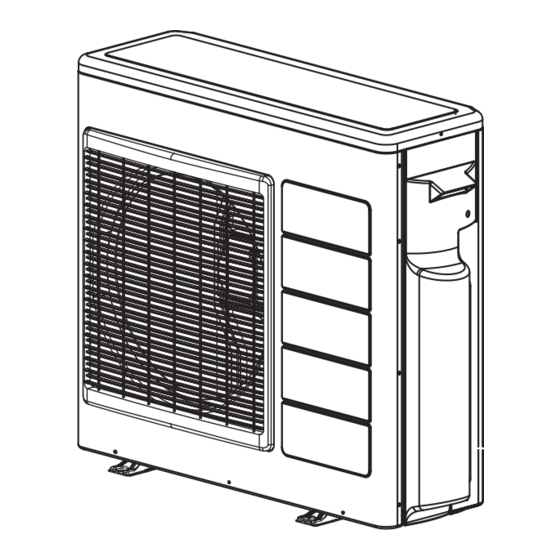
Page 20: Construction And Dimensional Diagram
CONSTRUCTION AND DIMENSIONAL DIAGRAM MODEL RAM-71QH5 Handle Handle Air outlet Air suction grille More than More than Fixing hole Service space – 19 –... -
Page 21: Main Parts Component
MAIN PARTS COMPONENT FAN MOTOR Fan Motor Specifications MODEL RAM-71QH5 POWER SOURCE DC : 350V OUTPUT 350V CONNECTION 0-6V 0-15V (Control circuit built in) 20˚C — (68 ˚F) RESISTANCE VALUE 75˚C — (167 ˚F) BLU : BLUE YEL : YELLOW... - Page 22 COMPRESSOR MOTOR Compressor Motor Specifications MODEL RAM-71QH5 COMPRESSOR MODEL JU1015D2 PHASE SINGLE RATED VOLTAGE AC 220 ~ 240 V RATED FREQUENCY 50 Hz POLE NUMBER WHITE CONNECTION YELLOW 20°C 2M = 1.05 (68°F) RESISTANCE VALUE 75°C 2M = 1.268 (167°F)
-
Page 23: Wiring Diagram
WIRING DIAGRAM MODEL RAM-71QH5 – 23 –... -
Page 24: Circuit Diagram
CIRCUIT DIAGRAM MODEL RAM-71QH5 – 25 –... -
Page 25: Block Diagram
BLOCK DIAGRAM MODEL RAM-71QH5 Outdoor Unit Power source single phase 50Hz, 220-240V compressor System Magnetic relay Power Module Inrush current protection relay Rotor position SPM driver detector Overload current EEPROM detector Expansion valve 1 Fan motor Expansion valve drive circuit... - Page 26 – 29 –...
- Page 27 – 31 –...
- Page 28 [Outdoor temperature >STAROTP_C] TSKTM1_C1 [Outdoor temperature ≤STAROTP_C] TSKTM1_C2 – 33 –...
- Page 29 – 35 –...
- Page 30 – 37 –...
- Page 31 – 39 –...
- Page 32 – 41 –...
- Page 33 RAM-71QH5 Power Power Power Power Power Power Unit 1 Cooling Unit 2 Cooling Unit 3 Cooling Unit 4 Cooling Operation 1S 1S Rush-in prevention 100ms Power Turns on for heating Outdoor fan Target speed Start sequence Compressor [TSKTM1_C rotation speed...
- Page 34 RAM-71QH5 – 43 –...
- Page 35 MODEL RAM-71QH5 • Time chart when executing defrost (Unit 1 and Unit 2 operated, Unit 3 and Unit 4 stopped) Unit 1 Heating Unit 2 Heating Unit 3 Unit 4 Defrosting signal Unit 1 Defrost request Unit 2 Defrost request...
- Page 36 MODEL RAM-71QH5 Unit 1 Heating Unit 2 Heating Unit 3 Unit 4 Defrosting signal Unit 1 Defrost request Balancing request Unit 2 Balancing request Unit 3 Balancing request Unit 4 Balancing request Turns on 15 sec 30 sec for heating...
- Page 37 MODEL RAM-71QH5 FORCED COOLING In order to accumulate refrigerant, units operate in cooling cycle. Execution condition and operation status are shown below. [Execution condition] With neither indoor unit 1, 2, 3 and 4 not operated, when forced cooling switch is turned ON, forced cooling will be performed.
- Page 38 MODEL RAM-71QH5 When one unit is operated for cooling Unit 1 Cooling Unit 2 Unit 3 Unit 4 [NDWN_ON] [NDWN_OFF] Turns on for heating Outdoor fan —1 Decreases by 100 min /30 sec. —1 Increases by 50 min /30 sec.
- Page 39 Unit 1 Heating Unit 2 Unit 3 Unit 4 [NDWN_ON] [NDWN_OFF] Turns on for heating Outdoor fan —1 —1 Decreases by 100 min /30 sec. Increases by 50 min /30 sec. 30 sec 30 sec 30 sec 30 sec 30 sec 30 sec 30 sec Compressor rotation speed 20 sec 20 sec...
-
Page 40: Refrigerating Cycle Diagram
REFRIGERATING CYCLE DIAGRAM MODEL RAM-71QH5 – 49 –... -
Page 41: Description Of Main Circuit Operation
DESCRIPTION OF MAIN CIRCUIT OPERATION MODEL RAM-71QH5 Power Circuit REACTOR POWER P.W.B.(1/2) SPM2 COIL POWER RELAY 25A FUSE NF COIL VARISTOR 1 R002 R003 SURGE TB11 ICP RELAY ABSORBER TB11 R001 TB11 L007 GRN1 C103 R009 GRN2 L006 GRN3 DIODE STACK R005 Fig. - Page 42 – 51 –...
- Page 43 C001 to C008, C013, C014, C022 to C5, C888, C89, NF COIL1 From outdoor microcomputer to indoor microcomputer. The request signal output from microcomputer pin is input to the transmitting circuit. The transmitting circuit modulates this signal by approx. 38kHz high-frequency. This high-frequency signal is amplified by a transistor, superimposed on the DC 35V line via C801 (or C811, C821, C831) and L801 (or L802, L803, L804) and supplied to the indoor unit.
- Page 44 Fig. 2-1 shows the interface circuit used for the indoor and outdoor microcomputers to communicate with each other. R813 R812 C802 Q803 R810 IF transmit output (SDO) C804 R811 Micro computer C821 R821 IF receive input (SDI) I/F 0V C822 D101 Terminal board Indoor P.W.B.
- Page 45 Fig. 2-1 shows the interface circuit used for the indoor and outdoor microcomputers to communicate with each other. R813 R812 C802 Q803 R810 IF transmit output (SDO) C804 R811 Micro computer C821 R821 IF receive input (SDI) I/F 0V C822 D101 Terminal board Indoor P.W.B.
- Page 46 Fig. 2-1 shows the interface circuit used for the indoor and outdoor microcomputers to communicate with each other. R813 R812 C802 Q803 R810 IF transmit output (SDO) C804 R811 Micro computer C821 R821 IF receive input (SDI) I/F 0V C822 D101 Terminal board Indoor P.W.B.
- Page 47 Fig. 2-1 shows the interface circuit used for the indoor and outdoor microcomputers to communicate with each other. R813 R812 C802 Q803 R810 IF transmit output (SDO) C804 R811 Micro computer C821 R821 IF receive input (SDI) I/F 0V C822 D101 Terminal board Indoor P.W.B.
- Page 48 3. System power Module Circuit – 57 –...
- Page 49 0.7V Base of outdoor P.W.B Q801, Q802 , Q803 , Q804 Outdoor micro computer lndoor micro computer SDO Pin SDI Pin 35V DC line 33ms. 100ms. 1 frame Leader Fig. 2-2 Voltages Waveforms of indoor / Outdoor Micro computers (Outdoor to Indoor Communications) Base of outdoor P.W.B Q801, Q802, Q803, Q804 Outdoor micro computer lndoor micro computer SDO Pin...
- Page 50 Upper arm transistor Time Lower arm transistor V – – U – Fig. 3-2 Switching order of power module transistor chopped U transistor ON Voltage point 320-360V Chopping period Upper arm transistor Current at Fig. 3-3 Voltage waveform at each point –...
- Page 51 4. Power Supply Circuit Fig. 4-1 shows the power circuit. FUSE C790 — A — A — A — A C770 — B D735 R773 D730 — B C773 — B D731 R774 L702 D736 — B R775 R777 C776 R779 C769 C777...
- Page 52 – 61 –...
- Page 53 System Power Module 320-360V DC compressor motor U coil – – V coil – W coil DC current (Id) detection resistor Fig. 3-4 System Power module circuit (U + is OFF, V – is ON) Fig. 3-5 – 62 –...
- Page 54 5. Reversing valve control circuit CN25 Reversing valve D841 PQ841 Q841 Micro R843 computer R832 R841 DC voltmeter or multimeter Fig. 5-1 – 63 –...
- Page 55 6. Rotor magnetic pole position detection circuit lnverter DC brushless motor for compressor R502 +12V R505 R504 R503 R501 R604 R603 R602 R601 R605 C605 R606 C606 R607 R611 R610 R609 C607 R608 Fig. 6-1 Rotor magnetic pole position detection circuit –...
- Page 56 7. Peripheral circuit of microcomputer Fig. 7-1 shows the microcomputer and its peripheral circuits. Table 7-1, the basic operations of each circuit block, and Fig. 7-2, the system configuration. C224 Outdoor R290 Microcomputer Q209 Q205 R291 Reset terminal DC current Detection resistor R245 IP cutter...
- Page 57 8. Overload control circuit (OVL control circuit) Translation micro computer To power module negative terminal Judgement OVL with respect to Motor control externally set process (R503) value Detection resistor Judgement OVL Voltage amp. according to the rotation convarter circuit speed (Internal judgement) Primary Selects data according...
- Page 58 9. Reset circuit Fig. 9-1 12V line 5V line Reset voltage Time 12V line 5V line Reset voltage Time Fig. 9-2 – 67 –...
- Page 59 OH (overheat) thermistor and electric expansion valve thermistor so that they detect the temperatures of the unit and control the system. The circuit of the thermistors is shown as Fig. 10-1 for model RAM-71QH5 and their roles and temperature measuring points are shown as Table 10-1.
- Page 60 – 69 –...
- Page 61 When the connectors of the thermistors are disconnected or the thermistors is open or short, LD301 (red) lights and LD302 (red) blinks so that they indicate troubled parts. Combinations of LD301 and LD302 are set up for indicating troubled thermistors. The correspondences between the number of blink time and troubled parts are shown as Table 10-3. Look in the table (LD301 and LD302 blink) for troubled parts, and if the disconnections of them are checked out, they are replaced.
- Page 62 11. Electric expansion valve MICRO COMPUTER Table 11-1 The electric expansion valve is driven by DC 12V. Power is supplied to 1 or 2 phases of 4-phase winding to switch magnetic pole of winding in order to control opening degree. Relationship between power switching direction of phase and open/close direction is shown below.
- Page 63 Pin No. 0.9V 50ms 75ms 200ms Fig. 11-2 With expansion valve control, opening degree is adjusted to stabilize target temperature, by detecting temperature of compressor head. The period of control is about once per 20 seconds, and output a few pulses. 12.
- Page 64 INSPECTING OUTDOOR ELECTRICAL PARTS Check to see that the LED is either on or blinking. Carry out inspections by examining the on/blinking status of LEDs 301-304. LED number LD301 LD302 LD303 LD304 Status Checkpoints Name Diagnosis Diagnosis Communications Operation lamp 1 lamp 2 lamp lamp...
- Page 65 Inspection method 1 LED on Insert the power source, and check to see that the Follow "Inspecting external electrical parts" and check LED is on. the cause of the problem. LED off Connect a commercial-use 220-240V power source Is AC230V flowign to the L/N terminal? to the L/N terminal.
- Page 66 Inspection method 2 Check the number of times LD301 blinks. LD301: Blinks once The power source or some other reason may have caused the microcomputer Reset stop to reset. Replace the control P.W.B. if the LED blinks once and then stops frequently during operation.
- Page 67 Outdoor fan rotates LD301: Blinks five times Insert the power source and operate, and then check to see that the outdoor fan is Overload stop rotating Outdoor fan rotates, but soon stops. The protection circuit may cause the fan to stop when Replace the fan motor.
- Page 68 O.K. AC196V-265V LD301: Blinks ten times Check the power source voltage Check the wiring (diode stack (terminal board, L/N terminal) Power source voltage blue/yellow/gray/red) abnormally abnormally noise N.G. AC196V or less or AC265V or more Danger! Quickly turn off the power Less than AC196V Turn off the power source, and remove the yellow source and replace the SPM2.
- Page 69 – 81 –...
- Page 70 note: If Indoor unit is not installed, the correspond error cord will be generated. Blinking of the LD304 has a priority from the smaller number of times. In case of some indoors are failed at same time, the LD304 shows the smallest blinking time first. After the first failure repaired, LD304 shows the next fail.
-
Page 71: How To Operate The Outdoor Unit Independently
HOW TO OPERATE USING THE SERVICE SWITCH THE OUTDOOR UNIT MODEL RAM-71QH5 1. Turn the Power switch off and then turn on again. 2. Remove the electrical parts cover. 3. Press the service switch for one second or more (wait for at least 30 seconds after turning the power source switch on). -
Page 72: Trouble Shooting
TROUBLE SHOOTING Model RAM-71QH5 PRECAUTIONS FOR CHECKING Power source 1 ø 220-240V, 50Hz DANGER 1. Remember that the 0V line is biased to 162V in reference to the ground level. 2. Also note that it takes about 10 minutes until the voltage fall after the power switch is turned off. - Page 73 Discharge procedure and how to cut off power to power circuit Caution DANGER Voltage of about 360V is charged at both ends of smoothing capacitor 330 µ F x 3. High voltage (DC 360V) is also charged at screw and terminal sections of system power module. During continuity check of each circuit of electrical parts in outdoor unit is performed, to prevent secondary trouble, disconnect red/gray wire connected to system power module (SPM) from diode stack.
- Page 74 Lighting mode self-diagnosis lamp RAM-71QH5 Location of self-diagnosis lamp – 86 –...
- Page 75 Lighting mode self-diagnosis lamp RAM-71QH5 – 87 –...
- Page 76 TROUBLESHOOTING OF THE SYSTEM POWER MODULE – 88 –...
- Page 77 – 89 –...
- Page 78 – 90 –...
-
Page 80: Parts List And Diagram
PARTS LIST AND DIAGRAM OUTDOOR UNIT MODEL : RAM-71QH5 – 91 –... - Page 81 MODEL RAM-71QH5 PART N0. Q’TY / UNIT PARTS NAME PMRAC-07CV1 2P TERMINAL FOR C-D LINE PMRAC-51CHA1 4P TERMINAL PMRAC-70YHA CABINET RAC-2226HV COMPRESSOR RUBBER PMRAM-72QH5 COMPRESSOR PMRAM-72QH5 CONDENSER PMRAC-70YHA D-GRILL-AS (INCL. MOUTH RING) PMRAM-72QH5 EXPANSION VALVE COIL (B) PMRAM-72QH5 EXPANSION VALVE COIL (R)
- Page 82 PART N0. Q’TY / UNIT PARTS NAME RAM-71QH5 PMRAM-72Q8 THERMISTOR (OH) PMRAM-65QH4 THERMISTOR (OUTSIDE TEMPERATURE) PMRAM-72QH5 THERMISTOR-PIPE (W) PMRAM-72QH5 THERMISTOR-PIPE (R) PMRAC-24CP5 TOP COVER PMSMARTY235M VALVE (2S) PMSMARTY235M VALVE (3S) PMRAC-70YHA NET COVER PMRAM-72QH5 EXPANSION VALVE PMRAM-72QH5 VALVE (4S) PMRAM-72QH5...
- Page 83 HITACHI PM NO. 0459E RAM-71QH5 – 94 – Printed in Malaysia...
Need help?
Do you have a question about the RAM-71QH5 and is the answer not in the manual?
Questions and answers