Advertisement

SERVICE MANUAL
TECHNICAL INFORMATION
FOR SERVICE PERSONNEL ONLY
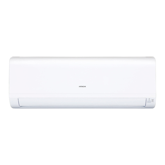
INDOOR UNIT
RAK-15QPC
RAK-18RPC
RAK-25RPC
This manual describes only points that differ from
RAM-33NP2B(PM NO.0581E)
RAM-40NP2B(PM NO.0582E)
RAM-53NP2B,RAM-53NP3B(PM NO.0583E)
RAM-68NP3B
(PM NO.0584E)
RAM-70NP4B
(PM NO.0585E)
RAM-90NP5B
(PM NO.0586E)
RAM-110NP6B
(PM NO.0587E)
RAC-18WP RAC-25WPC (HHAW NO.0100E)
C,
for items not described in this manual.
Indoor unit
Single outdoor unit
RAM-33NP2B
RAM-40NP2B
RAM-53NP2B
RAM-53NP3B
Multi
outdoor unit
RAM-68NP3B
RAM-70NP4B
RAM-90NP5B
RAM-110NP6B
SPECIFICATIONS
TYPE
MODEL
POWER SOURCE
TOTAL INPUT (W
TOTAL AMPERES (A)
COOLING
(KW)
CAPACITY
(B.T.U./h)
TOTAL INPUT (W
TOTAL AMPERES (A)
HEATING
(KW)
CAPACITY
(B.T.U./h)
W
DIMENSIONS
H
(mm)
D
NET WEIGHT
(Kg)
SPECIFICATIONS AND PARTS ARE SUBJECT TO CHANGE FOR IMPROVEMENT
ROOM AIR CONDITIONER
Johnson Controls- Hitachi Air Conditioning Wuhu Co., Ltd.
RAR-6N1
RAK-15QPC
-
o
o
o
o
o
o
o
o
OUTDOOR UNIT
INDOOR UNIT
RAK-18R
PC
RAC-18W
1 PHASE,50Hz,220-230V
550 (
250
1010
)
3.12-2.97
2.00 (0.90 2.50)
8,530 (3,070 10,920)
580 (250 970)
3.49-3.34
2.50 (0.90
3.20)
11,600 (3,070 15,010)
780
660(+60)
280
530
218
278(+35)
7.5
27.5
INDOOR UNIT
1
HHAW NO.0099E
RAK-15QPC
RAK-18RPC
RAK-25RPC
REFER TO THE FOUNDATION MANUAL
CONTENTS
SPECIFICATIONS ------------------------------------------------------------------- 6
HOW TO USE ---------------------------------------------------------------------- 9
CONSTRUCTION AND DIMENSIONAL DIAGRAM --------------------- 29
MAIN PARTS COMPONENT --------------------------------------------------- 30
WIRING DIAGRAM ---------------------------------------------------------------- 31
CIRCUIT DIAGRAM --------------------------------------------------------------- 33
BLOCK DIAGRAM ----------------------------------------------------------------- 35
BASIC MODE ----------------------------------------------------------------------- 36
REFRIGERATING CYCLE DIAGRAM --------------------------------------- 48
DESCRIPTION OF MAIN CIRCUIT OPERATION ----------------------- 51
VARIOUS SETTINGS -----------------------------------------------------------------
PARTS LIST AND DIAGRAM -------------------------------------------------- 88
RAC-18WPC
o
o
o
o
o
o
o
o
DC INVERTER
INDOOR UNIT
P
C
RAK-25R
PC
1 PHASE,50Hz,220-230V
780
280
218
7.5
49
60
70
RAC-25WPC
o
o
o
o
o
o
o
o
OUTDOOR UNIT
RAC-25W
PC
700 (250
1,290)
3.75-3.59
2.50 (0.90 3.10)
8,530 (3,070 10,580)
880 (250 1,250)
4.56-4.36
3.40 (0.90 4.40)
11,600 (3,070 15,010)
660(+60)
530
278(+35)
27.5
After installation

Advertisement

Table of Contents
loading

Summary of Contents for Hitachi RAK-15QPC

  • Page 1: Table Of Contents

    11,600 (3,070 15,010) 11,600 (3,070 15,010) 660(+60) 660(+60) DIMENSIONS (mm) 278(+35) 278(+35) NET WEIGHT (Kg) 27.5 27.5 After installation SPECIFICATIONS AND PARTS ARE SUBJECT TO CHANGE FOR IMPROVEMENT ROOM AIR CONDITIONER INDOOR UNIT Johnson Controls- Hitachi Air Conditioning Wuhu Co., Ltd.
  • Page 2 6$)(7< '85,1* 5(3$,5 :25.  ,Q RUGHU WR GLVDVVHPEOH DQG UHSDLU WKH XQLW LQ TXHVWLRQ EH VXUH WR GLVFRQQHFW WKH SRZHU FRUG SOXJ IURP WKH SRZHU RXWOHW EHIRUH VWDUWLQJ WKH ZRUN  ,I LW LV QHFHVVDU\ WR UHSODFH DQ\ SDUWV WKH\ VKRXOG EH UHSODFHG ZLWK UHVSHFWLYH JHQXLQH SDUWV IRU WKH XQLW DQG WKH UHSODFHPHQW PXVW EH HIIHFWHG LQ FRUUHFW PDQQHU DFFRUGLQJ WR WKH LQVWUXFWLRQV LQ WKH 6HUYLFH 0DQXDO RI WKH XQLW ,I WKH FRQWDFWV RI HOHFWULFDO...
  • Page 3 WORKING STANDARDS FOR PREVENTING BREAKAGE OF SEMICONDUCTORS 1. Scope The standards provide for items to be generally observed in carrying and handling semiconductors in relative manufactures during maintenance and handling thereof. (They apply the same to handling of abnormal goods such as rejected goods being returned.) 2.
  • Page 4 (6) Use a three wire type soldering iron including a grounding wire. Metal plate (of Al. stainless steel, etc.) Bare copper wire (for body earth) Working table Resistor 1MΩ(1/2W) Staple Earth wire Fig.3 Grounding of the working table soldering iron Grounding wire Screw stop at the screwed part using a rag plate...
  • Page 5 CAUTION In quiet or stop operation, slight flowing noise of refrigerant in the refrigerating cycle is heard occasionally, but this noise is not abnormal for the operation. When it thunders near by, it is recommend to stop the operation and turn off the circuit break er for safety. In the event of power failure,the room air conditioner will restare automatically in the previously selected mode once the power is restored.
  • Page 6: Specifications

    SPECIFICATIONS MODEL RAK-15QPC,RAK-18RPC,RAK-25RPC 30W (DC325 V) FAN MOTOR FAN MOTOR CAPACITOR FAN MOTOR PROTECTOR – COMPRESSOR COMPRESSOR MOTOR CAPACITOR OVERLOAD PROTECTOR OVERHEAT PROTECTOR FUSE (for MICROPROCESSOR) 3.15A POWER RELAY POWER SWITCH TEMPORARY SWITCH SERVICE SWITCH TRANSFORMER 450NR VARISTOR NOISE SUPPRESSOR...
  • Page 7 Figure showing the installation of lndoor unit MODEL RAK-15Q PC RAK-18RPC RAK-25RPC above 50mm above 50mm above 50mm Be sure to completely seal any gap with putty. 2300 mm or more Plug The indoor piping should be insulated with the enclosed insulation pipe.
  • Page 8 Main PCB. SWITCH POSITION CAPACITY SELECTION 1.0kW 1.5kW 1.0kW 1.0kW 1.5kW 1.5kW NOTE: FACTORY default setting is at 1.5kW capacity. This setting is applicable for RAK-15QPC only.
  • Page 23 During cooling and dehumidifying operation, do not keep the deflectors swinging or in the lower position (in the case of vertical auto swing) for a long time. It may cause dew condensation on the deflectors. RAK-15QPC,RAK-18/25RPC When cooling, When heating dehumidifying...
  • Page 29: Construction And Dimensional Diagram

    CONSTRUCTION AND DIMENSIONAL DIAGRAM MODEL RAK-15Q PC ,RAK-18RPC ,RAK-25RPC INDOOR UNIT 19 .3 More than More than 50mm 50mm 37.5 47.5 Service space...
  • Page 30: Main Parts Component

    MAIN PARTS COMPONENT THERMOSTAT (Room temperature Thermistor) Thermostat Specifications RAK-15QPC,RAK-18RPC,RAK-25RPC THERMOSTAT MODEL OPERATION MODE 15.3 (59.54) 16.7 (62.06) INDICATION 15.0 (59.00) 16.7 (62.06) 23.3 (73.94) 24.7 (76.46) TEMPERATURE INDICATION ˚C (˚F) 23.0 (73.40) 24.7 (76.46) 31.3 (88.34) 32.7 (90.86) INDICATION 31.0...
  • Page 31: Wiring Diagram

    WIRING DIAGRAM RAK-15QPC,RAK-18RPC,RAK-25RPC...
  • Page 32 WIRING DIAGRAM OF THE PRINTED WIRING BOARD [Remote controller] RAR-6 N1 SWB~SW10 Carbon SW RAR-6 N1 Reset carbon SW Only for RAR-5E2...
  • Page 33: Circuit Diagram

    CIRCUIT DIAGRAM MODEL RAK-15QPC POWER FOR CLEANNESS...
  • Page 34 CIRCUIT DIAGRAM MODEL RAK-18RPC,RAK-25RPC POWER FOR CLEANNESS...
  • Page 35: Block Diagram

    BLOCK DIAGRAM MODEL RAK-15QPC,RAK-18RPC,RAK-25RPC INDOOR UNIT Outdoor unit Indoor / Outdoor interface circuit DC fan motor Indoor DC fan motor drive circuit Control Power circuit Reset circuit Indicating lamp Operation Timer Buzzer circuit Wireless receive Wireless remote /send circuit controller...
  • Page 36: Basic Mode

    MODEL RAK-15QPC,RAK-18RPC,RAK-25RPC...
  • Page 37 For the multi indoor unit MODEL RAK-15QP 1.5KW) RAK-15QP 1.0KW) RAK-18RPC RAK-25RP REQUIRED REQUIRED REQUIRED REQUIRED PROM NO. LABEL NAME VALUE OF UNIT VALUE OF UNIT VALUE OF UNIT VALUE OF UNIT WMAX_M 4900min 3900min 4900min 4900min WMAX2_M 4900min 3900min 4900min 4900min WSTD_M...
  • Page 38 For the single indoor unit Table 1 Mode data file MODEL RAK-18RPC RAK-25RPC LABEL NAME VALUE WMAX 4200 min-1 6200 min-1 WMAX2 4200 min-1 6200 min-1 WSTD 3000 min-1 4500 min-1 WJKMAX 2800 min-1 4200 min-1 WBEMAX 2800 min-1 3800 min-1 WSZMAX 2800 min-1 3700 min-1...
  • Page 39 ,for RAK-15Q PB,RAK-18/ 25/ 50RPB only Notes: (1) Condition for entering into Cool Dashed mode. When fan set to “Hi” or “Auto and when the compressor speed (P section) due to temperature difference between setting temperature (including the correction shift only) and room temperature is CMAX or higher. (2) Cool Dashed will release when i) a maximum 25 minutes is lapsed and ii) room temperature is lower than set temperature –3°C (thermo off) and iii) when room temperature has achieved setting temperature –1°C then maximum Cool Dashed time will be revised to 20 minutes.
  • Page 40 ,for RAK-15Q PB,RAK-18/ 25/ 50RPB only (1) Pressing the "POWERFUL" button will reduce the temperature setting by PWSFTC. (2) The powerful operation is for 20 minutes after setting. (3) Operation is continued forcibly thermo-ON for 20 minutes after the powerful operation is finished. (4) Pressing the "START/STOP"...
  • Page 41 ,for RAK-15Q PB,RAK-18/ 25/ 50RPB only Notes: (1) If the room temperature is (cooling preset temperature) - (1.33°C) or less after 30 seconds from starting the operation, the operation is done assuming as the preset temperature = (room temperature at the time) - (2°C). (2) The indoor fan is operated in the “Lo”...
  • Page 42 (1) Pressing the "POWERFUL" button will reduce the temperature setting by PWSFTSD. (2) The powerful operation is for 20 minutes after setting. (3) Operation is continued forcibly thermo-ON for 20 minutes after the powerful operation is finished. (4) Pressing the "START/STOP" button and "POWERFUL"button during powerful operation wil cancel the powerful operation. (5) If the sleep timer is set during powerful operation, the powerful operation will be canceled.
  • Page 43 ,for RAK-15Q PB,RAK-18/ 25/ 50RPB only Notes: (1) Condition for entering into hot dashed mode. When fan set to "Hi" or "Auto" and i) room temperature is 18 or less, and ii) outdoor temperature is 10 or less, and iii) compressor speed (P section) due to temperature difference between setting temperature(including shift value only) and room temperature is WMAX or more.
  • Page 44 SILENT Silent button Indoor WSZMAX/CSZMAX Compresson speed Outdoor Notes: Can’t set POWERFUL and SILENT at the same time. Setting Defrosting Inhibit Period DFTIM_OT P5 DFTIM_OTP 10 DFTIM_OT P0 Outdoor temperature – 1 0 – 5˚C ˚C Notes: The first inhibit time after operation start is set to DFTIM_FST. From the second time onwards, the inhibit time is set according to the time required for defrosting.
  • Page 45 Same as Basic Heating operation (1) Pressing the "POWERFUL" button will increase the temperature setting by PWSFTW. (2) The powerful operation is for 20 minutes after setting. (3) Operation is continued forcibly thermo-ON for 20 minutes after the powerful operation is finished. (4) Defrost is inhibited for 20 minutes after the start of the powerful operation.
  • Page 46 ECO button Cooling:0.66 Dehumidifying:0.66 Set temperature Heating:0.66 FCLN_WAM_P FCLN_SDF_P Current restrict Compressor speed CLNCMP Notes: Can’t set POWERFUL and ECO at the same time. During FAN operation,can’t set ECO.
  • Page 47 RAK-15QPC RAK-18RPC RAK- Reversing valve defrosting...
  • Page 48: Refrigerating Cycle Diagram

    MODEL RAK-15Q PC RAK-18RPC RAK-25RP INDOOR UNIT OUTDOOR UNIT Outdoor unit INDOOR UNIT OUTDOOR UNIT Outdoor unit...
  • Page 49: Procedure For Disassembly And Reassembly

    Procedure for Disassembly and Reassembly INDOOR UNIT RAK-15 Q PC,RAK-18RPC,RAK-25RPC Front Panel 3. Control P .W.B. and Indicating P.W.B Be sure to hold the front panel with both hands to detach and attach it. (1)Remove each connector from the lead wire. (2)Remove the four P.W.B.
  • Page 50 4. Tangential air flow fan and fan motor Press to lower the hook at the center of theunit a little and pull the claw forward to removethe drain pan. 18/25PPC only have one Fig. 4 (2) Remove the screws from the upper and lower bearing covers. (3) Remove the locking hook of the lower bearing cover from the Cabinet.
  • Page 51: Description Of Main Circuit Operation

    DESCRIPTION OF MAIN CIRCUIT OPERATION RAK-15QPC,RAK-18RPC,RAK-25RPC 1. Control power circuit Switching power circuit Fig. 1-1 ・ An AC power supply from outdoor unit passes through the 3.15 A fuse, varistor (VA001), and noise filter circuit and rectified and smoothed by DB1 and C003 to become a DC current 325 V. It is then supplied to indoor fan motor drive circuit,and switching power circuit.
  • Page 52 2. Reset Circuit Reset R503 Microcomputer R502 IC501 Fig.2-1 Timing chart Voltage 5 . 0V pin of IC501 supply voltage RES detecting voltage RES canceling voltage 4 . 4V 4 . 2V Voltage pin of IC501 output voltage 5.0V pin of microcomputer Fig.2-2 Reset circuit is to initialize the indoor unit microcomputer when switching ON the power or after recovering from power failure.
  • Page 53 3. Drive circuit of the indoor fan motor Primary 325V Primary 18.5V Indoor fan motor Power siganl of indoor fan(from pin 57 of microcomputer) Primary 0 V Rotation speed feedback signal (to pin of microcomputer) Output signal of indoor fan (to pin of microcomputer) Fig.
  • Page 54 Caution The indoor fan motor and drive circuit are connected to the primary power supply. They therefore have voltage to ground. Guard against electric shocks. Caution ny circumstances detach or reattach a connector. Any such practice would cause a high voltage to r fan motor and board circuit being destroyed.
  • Page 55 6. Initial Setting Circuit (IC531) When power is supplied, the microcomputer reads the data in IC531 (E PROM) and sets the preheating activation value and the rating and maximum speed of the compressor, etc. to their initial values. Data of self-diagnosis mode is stored in IC531; data will not be erased even when power is turned off. Fig.
  • Page 56 7. Temporary Switch Circuit MICROCOMPUTER Temporary switch R405 TEMPORARY SW SW211 Fig. 7-1 The temporary switch is used to operate the air conditioner temporarily when the wireless remote control is lost or faulty. The air conditioner operates in the previous mode at the previously set temperature. However, when the power switch is set to OFF, it starts automatic operation.
  • Page 57 DSW1 R695 R903 R741 R905 R740 R906 R642 DSW1...
  • Page 58 11. Indoor/outdoor communication circuits Indoor unit side Outdoor unit side Inverter circuit Outdoor C302 microcomputer Indoor transmission circuit Indoor microcomputer (IC601) Outdoor Indoor/outdoor communication Outdoor reception chopper output (30kHz) reception circuit input Indoor transmission output Outdoor transmission circuit Outdoor transmission output Indoor reception input Indoor unit reception circuit...
  • Page 59 12. Stepping motor drive circuit Microcomputer Vertical vane, left Vertical vane, left Vertical vane, left Vertical vane, left Horizontal sweep motor Lateral vane Lateral vane Lateral vane Lateral vane Vertical sweep motor Fig. 12-1 [Connector circuit waveform while the motor runs] Voltage waveforms of different phases as viewed from the OV line while the motor rotor is turning counterclockwise as viewed from the shaft side...
  • Page 60: Service Call Q&A

    SERVICE CALL Q&A RAK-15QPC,RAK-18RPC,RAK-25RPC MODEL Cooling operation The compressor sometimes Cooling when the room Check if the heat stops during cooling. temperature is low may exchanger of the indoor cause the heat exchanger unit is covered with frost. of the indoor unit to gather Wait for 3 to 4 minutes frost.
  • Page 61 Common, etc. In fan speed "automatic" mode, In "automatic fan speed" mode, the This does not abnormal. It the product will sense the heat is because the cold fan indoor fan changes from strong fan speed exchange temperature and, speed prevention is working. to weak fan speed to slight fan speed.
  • Page 62 Wireless remote control The timer will not become set. Have you set the product to the current time? The timer cannot be set unless it is set to the current time. The current time When set to the current The current time display will disappears 10 seconds time setting, the reading disappear at once.
  • Page 63 STRUCTURE OF AN INDOOR UNIT ELECTRIC PARTS RAK-15QPC,RAK-18RPC,RAK-25RPC FIXTURE SCREW ELECTRICA L. COVER FIXTURE SCREW FIXTURE SCREW Removing electrical parts 1. Remove the electrical parts cover. 2. Remove the connectors from the CN4 (heat exchange thermistor), CN9,CN15 (stepping motor) and CN2 (fan motor).
  • Page 64 Other instructions (1) Detaching and reattaching the receptacles for tab terminal All the receptacles for connecting tab terminals are with a locking mechanism. Forcibly pulling any such receptacle without unlocking it will destroy it. Be on guard. When reconnecting it, insert it securely all the way home. ・Receptacle types and how to unlock them Mild resin cover Cancel button...
  • Page 65 Troubleshooting support Function Self-diagnosis display ・The failure mode detected on the indoor unit side is displayed by [Display on the indoor blinking the "timer lamp". And a failure detected on the outdoor unit side] unit side will be indicated by the "time lamp" blinking 4 times. ・If the outdoor unit side detects a failure, the product will first conduct several operation retrials.
  • Page 66 Self-diagnosis display function (indoor side display) While the "timer lamp" (orange), of the indoor unit is blinking, troubleshoot the product while referring to the table below. 1. How to count the lamp blinking frequency [An example of 5-time blinking] ・ The product will repeat blinking with 2-second 2-second 2-second intermissions.
  • Page 68 9 mes Indoor interface circuit broken 1. Indoor interface circuit (sigle only) 9 mes communica on error between indoor 12 mes Outdoor interface circuit broken 1. Outdoor interface circuit (sigle only) and outdoor units...
  • Page 69 Forced cooling operation (Only single connection) The cooling operation can be forcibly performed for collecting refrigerant and inspecting failures. Do not perform the forced cooling operation continuously for long hours, because the compressor continues to be in operational status, regardless of room temperature. <How to start the operation>...
  • Page 70: Various Settings

    37 and page 38...
  • Page 71 RAR-6N1, RAR-6N2, RAR-6N3, RAR-6N4, RAR-6N5 ) Please set the DIP switch No.6 to ON accordingly (Refe to page...
  • Page 74 tK d Kd tE'/ d t dD' Z&D ' d>E'd K' ZK^d WZK h,Z ^d Zd ^dKW Z ^ d Z ^ d < < ^d Zd ^dKW >/ > ZKKD d DW Z dFZ BKGH HKd C...
  • Page 75 tK d Kd tE'/ d t d>E'd W hdD'd KK^D'/d&Kh dh,ZD'/d t Z&KdK>> WZK h,Z WKG Z?FK HKd C E / d...
  • Page 76 Diagnosis and troubleshooting of indoor electric parts Initiating troubleshooting Are the "timer lamp" (orange) of the indoor unit Perform troubleshooting according to the blinking? self-diagnosis display. The product will begin to run in response to a remote control setting: "cooling mode, temperature setting 16 "...
  • Page 77 Checking the indoor unit electrical parts Introduction First check the failure phenomenon and status, and then move on to elaborate diagnosis. Initiating troubleshooting How many times does the time lamp Is the "timer lamp" (orange) of the indoor unit blinking? blinding not 4 times 4 times...
  • Page 78 1. Failure phenomenon: The power will not become turned on. Neither initialization, remote control, nor any other step works on the vane position at power-on. Situation Estimated cause of fuse blowout ・ Abnormally high voltage applied to the power supply [ Estimated failure ・...
  • Page 79 2.Failure phenomenon: The product will not receive a remote control signal. Situation The product does not receive a remote control signal. It is not very responsive. (The product does run normally in response to the emergency operation switch.) Estimated failure ・...
  • Page 80 How to identify sources of jamming in the reception of remote control signals [ Situation ] The product may become poorly responsive to remote control signals due to external factors even though the product itself is trouble-free. [ Estimating sources of jamming ] Identify the installation status of the air-conditioner and the indoor and outdoor environments to identify possible causes of the jamming.
  • Page 81 Effects of other Checking points ・Check the effects of light and power noises coming from other electrical products. electrical products ・Turn on and off the electrical products, turn off the power and turn on the power, and check their effects on the reception of remote control signals.
  • Page 82 3. Failure phenomenon: The compressor will not run. [ Situation ] The compressor will not run (the same state as the thermometer turned off), the product receives remote control signals normally. The self-diagnosis lamp (LD301) of the outdoor unit blinks once or becomes turned off. [ Estimated failure locations ] ・Room temperature thermistor, heat exchanger thermistor ・...
  • Page 83 4. Failure phenomenon: The fan motor will not stop. Situation I have conducted the stop operation on the product by remote control, but the indoor fan motor will not stop. (It stopped about 10 minutes later.) Estimated failure locations ・Indoor fan motor ・Fan motor drive circuit Diagnosis flow Initiating troubleshooting...
  • Page 84 5. Timer lamp blinking: blinking once [Situation] The timer lamp blinks one time and the product will not operate. (This is not a sign of a breakdown.) [Estimated failure locations] ・ Reversing valve defective. ・ The refrigerating cycle block gas leak. 6.
  • Page 85 9. Timer lamp blinking: blinking 9 times [Situation] The timer lamp blinks 9 times and the product will not run. [Estimated failure location] Loose connector, wire break, or short-circuit in the room temperature thermistor, heat exchanger thermistor. [Cautions] Starting the product by remote control will initiate failure detection. (Merely turning on the power will not activate the failure detection function.) [Diagnosis flow] Initiating troubleshooting...
  • Page 86 10. Timer lamp blinking: blinking 10 times [Situation] The timer lamp blinks 10 times and the product will not run. ・ [Estimated failure locations] ・Loose connector or wire break in the indoor fan motor ・ Indoor fan motor mechanically locked ・Indoor fan motor ・Indoor fan motor drive circuit [Diagnosis flow]...
  • Page 87 11. Timer lamp blinking: blinking 12 times [Situation] The timer blinks 12 times and the product will not run. [Estimated failure locations] Erroneous connection in the indoor-outdoor connection line (F cable) Forget to connect CN27 of outdoor P.W.B Wire break or poor insertion of the indoor-outdoor connection line (F cable) Electrical parts in the outdoor unit (communication circuit, power circuit error) Communication error due to noise in other home electronics This does not constitute a failure in the air-conditioner...
  • Page 88: Parts List And Diagram

    PARTS LIST AND DIAGRAM INDOOR UNIT MODEL: RAK-15QPC,RAK-18RPC,RAK-25RPC...
  • Page 89 INDOOR UNIT Q'TY/U HHAW PARTS NO PARTS NAME HWRAS-25YHA5 CABINET ASS'Y HWRAK-18PSPA DRAIN CAP HWRAS-K10HCG FAN MOTOR HWRAK-18PSPA TANGENTIAL AIR FLOW FAN HWRAK-18RPC FAN SUPPORT ASS'Y HWRAS-E10H3 FAN COVER HWRAS-K10HCG FAN MOTOR SUPPORT HWRAS-K14HCG EVAPORATOR ASS'Y HWRAS-E10H3 PIPING ASS'Y HWRAS-E10H3 UPPER COVER HWRAS-25YH4 SPRING...
  • Page 90: Rak-18Rpc Rak-25Rpc

    RAK-15QPC HHAW NO.0099E RAK-18RP RAK-25RP...

Table of Contents