
Related Manuals for POD Point PP_2111


Summary of Contents for POD Point PP_2111
- Page 1 Electric Vehicle Charging Infrastructure Installation Guide Twin Charge 13/32 and 32/32 Models PP_2111 PP_2151 PP_2152...
-
Page 2: Table Of Contents
All POD Points use industry-standard foundations and electrical connections – making them extremely easy to install and connect using existing contractors with minimal additional training. This document gives an outline of what is required for installing a POD Point from a civil and electrical perspective. Pg.1 Version 2.2 2012... -
Page 3: Section 0: Before You Begin
- 99dBm to 91dBm: Communication is unlikely to be established. Note: the POD Point can still operate in standalone mode, but usage data and remote support will not be available. If any of the above requirements are not satisfied, please consult POD Point on 0207 247 4114. -
Page 4: Section 1: Contents Of Box
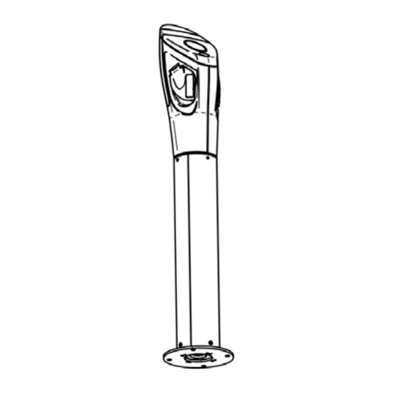
Section 1 : Contents of Box Mechanical Depending on model, your POD Point may be shipped in a complete unit, or as three modules: Module 1: Charging head (containing charging sockets and control circuitry) Module 2: Power post (containing the electrical distribution and safety equipment) - Page 5 Replace red cover on power distribution box Insert fuse(s) (supplied with the power head) and affix the appropriate rating label to the fuse holders. Note for 13/32 models (PP_2111) the 16A fuse MUST be installed in the right hand fuseholder. Install power head 8.1 Insert the power head onto the post (make sure that the face of the head is pointing the right way, that the internal...
-
Page 6: Section 2: Civil Work
32mm Rigiduct. It is very important that the foundation is level in all axes, as this controls the angle of the POD Point. It is also very important to orientate the foundation correctly, as this controls the orientation of the POD Point. (see Section 2.1). If required, it is possible to stabilise the subterranean foundation by inserting suitable lengths of 5/6mm rod through the two offset pairs of holes in the bottom of the unit. -
Page 7: Section 3: Electrical Work
POD Point to discuss this). Each POD Point also needs a separate earth (not connected to neutral) usually supplied by an Earth spike or mat (TT system), which is fed into the POD Point via a separate conductor. The earth should have a maximum resistance of 20 ohms. -
Page 8: Section 3.1: Dedicated Supply Direct Onto Main
This format is typically utilised on street, where there is no existing power supply. It typically involves live spicing onto the low voltage main which can only be carried out by the local Distribution Network Operator. The specification of cabling entering the POD Point is usually defined by the Distribution Network Operator. 16mm double insulated tails are typical. A feeder pillar will be required for this type of installation. -
Page 9: Section 3.2: Extension To Existing Supply
BS3036. (Table 7.1 in the Onsite Guide of BS7671 2008). `This device is at the supply end. POD Point is protected internally by at 30ms RCD, therefore if an additional RCD is required for the installation, it must be a time delay type such as Time Delay DP RCCB type ‘S’... -
Page 10: Section 4: Final Connect Up & Commissioning The Installation
The main power supply to the POD Point should now be switched on. Once the main supply has been switched on, the POD Point will take approximately 1 minute to “boot up”, and perform a diagnostic self check. -
Page 11: Appendix A: Commissioning Handover Certificate
Word. Please complete Sections 1, 2, 3 and 4. POD Point will complete Sections 5 and 6, to finalise activation. The completed certificate may be returned for the post owner, on request. - Page 12 On behalf of the installer, I hereby confirm that: We have completed the installation in accordance with the Installation Manual; the POD Point has been connected to the electricity supply and commissioned; the installation has been tested for electrical safety;...
-
Page 13: Appendix B: Troubleshooting
“Please swipe your tag to begin”. If this is not successful, call the installation team at POD Point on 020 7247 4114 Version 2.2 2012 POD Point Limited w: www.pod-point.com t: 0207 247 4114 e: enquiries@pod-point.com Pg. 12... -
Page 14: Appendix C: Signage, Bay Markings And Guards
3in pole. Custom designs are available on request Bay Markings and Guards Standard POD Point bay markings are marked out in thermo plastic paint as follows: Custom designs are available on request POD Points can be supplied complete with 600/900mm high floor or wall mounted guarda.
Need help?
Do you have a question about the PP_2111 and is the answer not in the manual?
Questions and answers