Advertisement
Quick Links
Advertisement

Related Manuals for POD Point Solo 3 - Home


Summary of Contents for POD Point Solo 3 - Home
- Page 1 Fast Charging Solo 3 - Home Install Guide Solo 3 - Home PP-D-210449-2 Install Guide S3-UK-H-IG...
-
Page 2: Important Safety Information
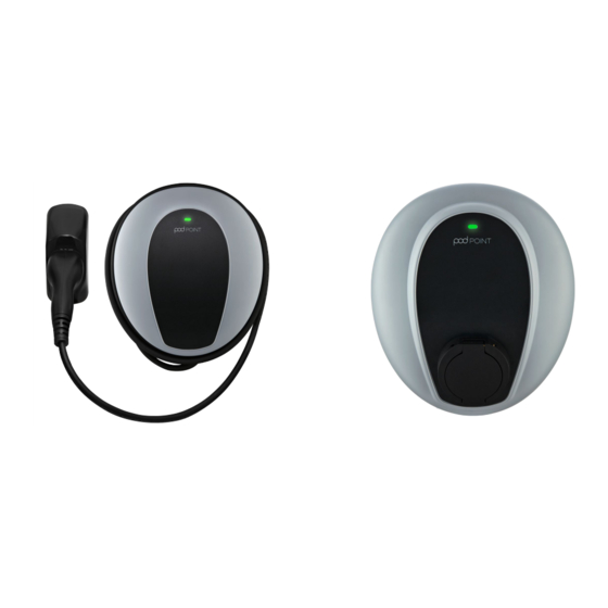
Solo 3 - Home This document details the install guidance for the Solo 3 (Home) variant of the Solo 3 product family. The Solo 3 is designed for installations inside or outside, with the advanced safety systems we have built into the charger ensuring its safe usage. This guidance provides information to assist when installing the Solo 3. - Page 3 Technical details RCD protection: The Solo 3 is a Class I/II rated device, All Pod Point Solo 3s include 6mA DC vehicle fault protection and only Type A RCD/RCBOs pollution degree 3 for 230V / 400V AC 50Hz are required at source.
- Page 4 Solo 3 - Home Transformers nstallation procedure If a galvanically isolated transformer is required, Note: national or local regulations not related to it should be placed upstream of the EVSE. The electrical works are not covered in this guide. neutral output feed of the transformer should be Relevant H&S at work, building regulations etc.
- Page 5 Solo 3 - Home Drilling the holes for the electrical Drilling template (box insert) supply cable entry Fig. 4 The Solo 3 has been designed to accept supply cable entry on either the left, right, bottom or via the rear. Top entry is only possible if there is no risk of water ingress (indoor).
- Page 6 “loads” should be measured by the CT. Live3: Grey Where the only available supply cable includes Neutral: Blue PV or storage “export” energy, contact Pod Point Earth: Green/Yellow to configure the unit to work with these. Screened cable External Current Transformer orientation Signal (usually Red) The “split core”...
- Page 7 Solo 3 - Home If a consumer unit includes a spare non-RCD Setting up the Solo 3 protected circuit, this may be used to supply the additional “mini” consumer unit. Current rating, cable overcurrent protection and load Use recommended torque settings for all MCB, curtailment settings must be set before testing and RCD and terminal blocks.
- Page 8 Pod Point Solo Wi-Fi Connection Guide changed. If a Solo 3 is reported as stolen and its connection to the Pod Point network is attempted, it can be placed Scan this QR code to get to permanently out of service.
- Page 9 Solo 3 using the MAC address may be the only option. The MAC address can be provided To commission a domestic Pod by Pod Point from the PSL number of the unit Point charger please complete which can then be included in the router’s the commissioning form at: allowlist.
- Page 10 Pod Point Solo 3 should change colours customers, including how to connect the Solo as follows: 3 to Wi-Fi, how to commission Pod Point chargepoints, and various troubleshooting 1. Establishing communication with guides and tips.
Need help?
Do you have a question about the Solo 3 - Home and is the answer not in the manual?
Questions and answers