Table of Contents
Advertisement
Quick Links
Advertisement
Table of Contents

Related Manuals for Lindy iSWITCH


Summary of Contents for Lindy iSWITCH
- Page 1 (iSWITCH) User’s Manual 20020925 Rev4...
-
Page 2: Table Of Contents
Warnings Quick Install Procedure Introduction Remote Power Manager (iSwitch) Features iSwitch Package Setup Procedure Setup via the USB Port Setup via the Serial Port Setup via the Ethernet Port Telnet Configuration Web-Based Configuration Firmware Upgrade Procedures Telephone Access Interface Daisy Chaining... -
Page 3: Warnings
NOTICE: This equipment has been tested and found to comply with the limits for a “Class B digital device, pursuant to Part 15 of the FCC rules. These limits are designed to provide reasonable protection against harmful interference when the equipment is operated in a commercial environment. This equipment generates, uses and can radiate radio frequency energy and if not installed and used in accordance with the instruction manual, may cause interference to radio communications. -
Page 4: Quick Install Procedure
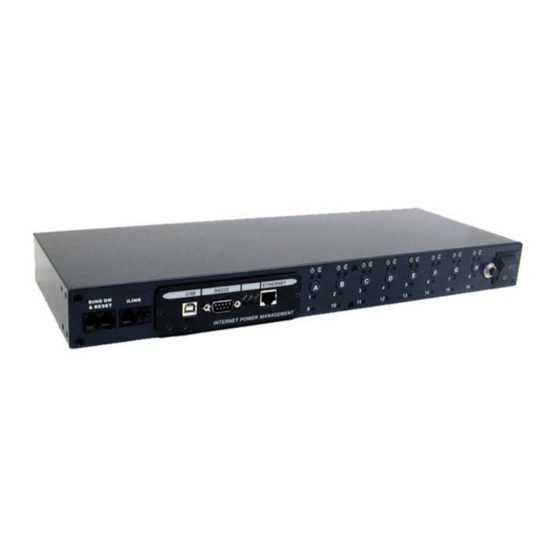
RJ11 connections on the rear panel are disconnected if they contain a plug in the housing. The iSwitch comes with brackets for mounting in a standard 19-inch rack. To mount the iSwitch into a rack perform the following procedure: 1. - Page 5 Panel iLink Port is for Daisy Chaining Ring On/Reset Port – Connect a telephone line to control the iSwitch Receptacle Control Status LED (Green) Receptacle Status LED (Red) Active Module LED (Yellow) Momentary switch for Receptacle Setup via USB Port...
- Page 6 When the LED is off, the momentary switch is active and the receptacle may be turned on or off by pressing and releasing the switch. Pressing and holding the momentary switch for three seconds will change the state from remote to local control.
-
Page 7: Introduction
Internet ready — Individually control each of the eight AC receptacles by using a Web Browser. Remotely and individually reboot locked up servers. If the network locks up, you can use the telephone to control the iSwitch to shutdown or to reboot locked up devices or servers. -
Page 8: Setup Procedure
Setup via the USB Port The following items must be obtained before attempting to setup the iSwitch: A valid IP Address, a USB Cable (provided), the USB Driver/USB setup file (enclosed diskette) and a PC with Windows 98 or higher. - Page 9 8.The Hardware wizard will guide you through installing the USB Driver. Click Next. 9. Hardware wizard will search for the best USB Driver. Click Next. 10. Check, Specify a location. Click Browse.
- Page 10 11. Open the appropriate 3½″ Floppy Drive. Open the USB folder. Open the Driver folder. Click OK. 12. Windows will search for the new USB Driver. Click Next. 13. Windows has found the USB Driver for the USB device. Click Next.
- Page 11 14. Windows has found the best Driver for this USB device. Click Next. 15. Windows is copying the USB Driver files to your “C:” drive. Click Next 16.Windows is finished installing the USB Driver. Click Finish. To your “C:” drive. Click Next...
- Page 12 17. On the Desktop, right click “My Computer”. Open Properties. 18. Open the Device Manager. Wait for approximately 30 seconds for the “Human Interface Device” to appear. Open the Human Interface Device. Click on “Usb- interface power device”. Click Open Windows Explorer. Open the appropriate 3½″ Floppy Drive. Open the USB folder. Open USBSetup.exe.
- Page 13 21. This is the Power Device Configuration Tool screen. On the Toolbar open Configuration. Then open System. 22. This is the System Parameter Configuration screen fill in all the information: the IP Address, the Subnet Mask, the Default Route (Gateway) and the DNS Server.
- Page 14 23. This is the Power Device Configuration Tool screen. After you have entered in all of the pertinent information, you have to Update and Restart to save all the information that was entered into the System Parameter Configuration screen. The Update and Restart icon (with the red arrow) is right beneath the “Device”...
- Page 15 25. This is the Power Device Configuration screen. Click Yes to Update the Power Device. 26. This is the Device Parameter Transmitting screen. The Power Device is being Updated.
- Page 16 27. The Power Device has been successfully updated. Click 28. The Power Device has to be Restarted. Click Yes. 29. The USB Setup Procedure is complete. The iSwitch is fully operational. Unplug the USB Cable from the...
-
Page 17: Setup Via The Serial Port
NOTE: When using Hyper Terminal use Version 3.0 or higher. The following items must be obtained before attempting to setup the iSwitch: A valid IP Address, a DB9 female- to-female Serial Cable (provided). There are a wide variety of Terminal Emulation packages, but for the most part they should be very similar. - Page 18 7. Connect using the appropriate Com port. Click OK 8. Configure the port settings. Bits per second: “115200”, Data bits: “8”, Parity: “None”, Stop bits: “1”, Flow control: “None”. Click OK 9. On the Toolbar open the File menu, and then open Properties.
- Page 19 Crtl+H, Emulation: VT100, Telnet terminal: VT100, Backscroll buffer lines: 500. Click OK. Plug the iSwitch’s power cord into the AC outlet and turn the iSwitch on. 12. When the message “Press ‘/’ key within 5 seconds to enter console configuration”...
- Page 20 14. Ctrl-Z moves the cursor down and Ctrl-W moves the cursor up. Pick Network, then hit enter. 15. Enter in the IP Address, the Gateway Address, the Subnet Mask and the DNS (all required). Hit the “Escape” key to return to the main menu.
- Page 21 16. Arrow down to PPP Config and hit enter. Enter in the ISP dial number, the ISP account/password and the enable/disable dial-out interface (not required). Hit the “Escape” key to return to the main menu. 17. Arrow down to Mail and hit enter. Enter in the SMTP Server (not required). The user can add or delete email addresses.
- Page 22 18. Arrow down to Trap and hit enter. This screen allows the user to send Traps about the UPS to ten IP Addresses (not required). Also, you may determine the severity levels and what type of access, read only or read and write, to assign to a particular IP manager.
-
Page 23: Setup Via The Ethernet Port
22. All functions description please refer to Page 30. Setup via the Ethernet Port The following items must be obtained before attempting to setup the iSwitch: A valid IP Address, a Computer on the network and an Ethernet cable connected to the network. -
Page 24: Telnet Configuration
The first string is the IP Address; the second string is the MAC Address (which can be found on the front of the iSwitch). 7. At the MS-DOS prompt type: route add 192.166.7.19 210.67.4.155. Then hit enter. The first string is the IP Address and the second string is the Gateway Address. -
Page 25: Telnet Configuration
Telnet Configuration This section will guide you through finishing the configuration of the iSwitch using Telnet. NOTE: You must complete the appropriate Setup Procedure before proceeding with the Telnet Configuration. NOTE: You must have given the iSwitch an IP Address. - Page 26 4. Pick Network, then hit enter. 5. Pick IP, then hit enter. Input your IP Address, Gateway Address, Subnet Mask and the DNS (all required). Then hit the left arrow key to exit to the main menu.
- Page 27 Hit the left arrow key to return to the main menu. 8. Arrow down to Trap and hit enter. This screen allows the user to send Traps about the iSwitch to ten IP Addresses (not required). Also, you may determine the severity levels and what type of access, read only or...
- Page 28 read and write, to assign to a particular IP manager. Hit the left arrow key to return to the main menu. 9. Once you have finished with the entire configuration, arrow down to Save_Restart and hit enter. Make sure you want to overwrite the old settings (y/n)? Hit the y key, then hit enter.
- Page 29 10. After rebooting the system, the new settings will be activated. Reboot (y/n)? Hit the y key then hit enter. 11. The iSwitch has rebooted to activate the new settings. Click OK. Arrow down to exit then hit enter. 12. At the MS-DOS Prompt type exit, then hit enter.
-
Page 30: Web-Based Configuration
Manager (iSwitch). NOTE: You must complete the appropriate Setup Procedures before proceeding with the Web-Based- Configuration. The Ethernet cable is connected to the iSwitch and the iSwitch is on. 1. Startup a Web browser. 2. Type in your IP Address. - Page 31 This is the screen where you can set the Network parameters. After you have finished filling in all of the information, click Save. BOOT MODE: iSwitch support DHCP, BOOTP and FIXED IP...
- Page 32 An external modem is needed to connect to the front serial port of the iSwitch. The iSwitch support two ways using modem to connect directly. ISP Mode After dialing in the remote user must hang up after the third ring.
- Page 33 NOTE: Be sure to write down your Supervisor’s name/password and keep it in a safe place. If the user forgets the name/password the iSwitch will have to be Flash Upgraded before the user can access the iSwitch. NOTE: It will be enhanced the security level to MD5 after the Enable Security Login checked.
- Page 34 8. This is the screen where the administrator can enable the application program interface to certain users. After you have finished filling in the information, click Save. (Optional) 9. This is the screen where the administrator can give certain rights to certain users. After you have finished filling in the information, click Save.
- Page 35 The user can control each receptacle individually or all of them at the same time. The iSwitch has to be setup in the remote mode to control the receptacles via the Internet. The iSwitch can also be setup for the local mode.
- Page 36 2000, you need to have three setting for the UPS to configure it. Connect the communication port on the rear of iSWITCH to NT or WIN 2000 server with the PC Communication cable. Connect the corresponding outlet on the rear of iSWITCH to the NT or WIN 2000 server with the PC input power cord.
- Page 37 The safe shutdown feature has a configurable delay time to safely shutdown the NT server. Then click Save. 15.This screen allows the User to depend on the iSwitch event to set notification. There are five ways to notify user.
- Page 38 a. Pager Input the code defined by user himself to Alarm-Add and Alarm-Remove. b. Broadcast It must run an application in the client to receive this broadcast message. c. Logging Enable the event logging function.
- Page 39 d. Trap Set the SNMP trap. e. Mail Send the event to the user pre-set email account.
-
Page 40: Firmware Upgrade Procedures
NOTE: When using Hyper Terminal use Version 3.0 or higher. The following items must be obtained before attempting to upgrade the iSwitch: The firmware upgrade software, a DB9 female-to-female Serial Cable (provided). There are a wide variety of Terminal Emulation packages, but for the most part they should be very similar. - Page 41 3. Once the message “Check u- dram” appears hit the “c” key. Then at the cursor type “upall” then hit enter. Once the User hits enter, you have approximately thirty seconds to complete the next four steps. 4. Go to the tool bar and select Transfer.
- Page 42 5.Select “X modem” under Protocol. 6. Click Browse. Look in the location where the Firmware upgrade software is located. Select the File name: “test.bin” and click open.
- Page 43 7. Click Send. 8. The Firmware upgrade will take approximately eight minutes to complete.
- Page 44 9. The Firmware upgrade is complete. NOTE: The user has to reconfigure all of the settings after the Firmware upgrade is complete, because all of the user’s settings will default to the original default settings.
-
Page 45: Telephone Access Interface
Command format: XXNA#: XX - 00—16 is the iSwitch’s device number for a daisy chain, if there is no daisy chain, then any number is accepted. N - outlet number: 1(A)—8(H), 9 controls all the outlets. -
Page 46: Daisy Chaining
The Remote Power Manager (iSwitch) can be Daisy Chained up to a maximum of sixteen units. Each iSwitch in the Daisy Chain must have its own unique identification number. The default ID# is “0 “. The first iSwitch must have the Internet Power Management Card install and must be configured before you can begin Daisy Chaining any additional RPMs. - Page 47 17. Turn the master power switch on. 18. Configure the third iSwitch's ID number (each iSwitch must have it's own unique ID#, the default ID# is "0"). 19. If there are only three RPMs required for this application, then this completes the Daisy Chaining procedure and the RPMs are ready for use.
-
Page 48: Troubleshooting
The iSwitch will not communicate and all of the LEDs on the Internet Power Management card are ON. Solution: There has been a collision of the packets. The iSwitch needs to be reset. Turn the iSwitch off and wait for approximately one minute, then turn the iSwitch back ON. Problem: All the LEDs are off and all of the output receptacles are on. -
Page 49: Appendix
This section discusses: Communities, Gateways, IP Addresses, and Sub net masking. Communities A community is a string of printable ASCII characters that identifies a user group with the same access privileges. For example, a common community name is “public.” For security purposes, the SNMP agent validates requests before responding. The agent can be configured so that only trap managers that are members of a community can send requests and receive responses from a particular community. -
Page 50: Subnetting And Subnet Masks
Subnetting and Subnet Masks Subnetting divides a network address into sub-network addresses to accommodate more than one physical network on a logical network. For example: A Class B company has 100 LANs (Local Area Networks) with 100 to 200 nodes on each LAN. To classify the nodes by its LANs on one main network, this company segments the network address into 100 sub- network addresses. -
Page 51: Glossary
Specifically, the physical (hardware) address exists in this layer. Management Information Base—The database, i.e., set of variables maintained by a gateway running SNMP. Normally Closed —Refers to a contact switch that is normally closed. Network Interface Controller—The hardware interface to the physical connection to the network. -
Page 52: Obtaining Technical Assistance
In the event that the unit requires factory service, the technician will issue you a Return Material Authorization Number (RMA #). G. If the iSwitch is under warranty, the repairs will be done at no charge. If not, there will be a charge for repair.
Need help?
Do you have a question about the iSWITCH and is the answer not in the manual?
Questions and answers