Table of Contents
Advertisement
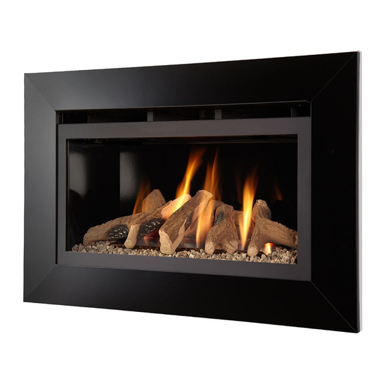
Eden HE MK2
HIGH EFFICIENCY BALANCED FLUE
INSET ROOM HEATER
Installation, Maintenance & User Instructions
Hand these instructions to the user
Model No's BBFG**RN2 is for use on Natural Gas (G20) at a supply pressure
of 20 mbar in G.B. / I.E.
Model No's BBFG**RP2 is for use on Propane Gas (G31) at a supply
pressure of 37 mbar in G.B. / I.E.
** Denotes trim & colour variant
Advertisement
Table of Contents

Related Manuals for BFM Europe Eden HE MK2

Summary of Contents for BFM Europe Eden HE MK2
- Page 1 Eden HE MK2 HIGH EFFICIENCY BALANCED FLUE INSET ROOM HEATER Installation, Maintenance & User Instructions Hand these instructions to the user Model No’s BBFG**RN2 is for use on Natural Gas (G20) at a supply pressure of 20 mbar in G.B. / I.E.
-
Page 2: Table Of Contents
Removal & replacing the glass frame assembly 53-54 Removal & re-fitting the fuel-bed logset 55-59 Removal & re-fitting the pebble fuel-bed pebble set Model numbers BBFG**RN2 & BBFG**RP2 are manufactured by:- BFM Europe Ltd. Trentham Lakes, Stoke-on-Trent, Staffordshire, ST4 4TJ... -
Page 3: Information And Requirements
SECTION 1 INFORMATION AND REQUIREMENTS APPLIANCE INFORMATION Main injector : (1 off) Stereomatic Cat 82 – size 2.00 (NG) Stereomatic Cat 82 – size 1.31 (LPG) Pilot Type : NG - Polidoro G27.2 LPG - Polidoro G24.1 Max. Gross Heat Input : 6.3 kW Min. -
Page 4: Conditions Of Installation
INSTALLATION REQUIREMENTS CONDITIONS OF INSTALLATION It is the law that all gas appliances are installed only by a GAS SAFE Registered Installer, in accordance with these installation instructions and the Gas Safety (Installation and Use) Regulations 1998 as amended. Failure to install appliances correctly could lead to prosecution. -
Page 5: Flue Terminal Position
FLUE TERMINAL POSITION The minimum acceptable dimensions from the flue terminal to obstructions and ventilation openings are shown below and listed in the table It is important that the position of the flue allows the free passage of air across it at all times. The minimum acceptable space from the flue terminal to obstructions and ventilation openings are specified below (figure 3). -
Page 6: Shelf Position
SHELF POSITION The fire may be fitted below a combustible shelf providing there is a minimum distance of 300mm above the top of the fire and the shelf does not project more than 150mm. If the shelf overhangs more than 150mm the distance between the fire and the shelf must be increased by 15mm for every 25mm of additional overhang over 150mm. -
Page 7: Installation Of Fire
SECTION 2 INSTALLATION OF FIRE UNPACKING THE COMBUSTION CHAMBER Carefully lift the combustion chamber out of the carton. Remove the loose item packaging carefully from the pack. Check the contents as listed :- DO NOT UNDER ANY CIRCUMSTANCES USE THIS APPLIANCE IF THE GLASS PANEL IS BROKEN OR NOT SECURELY FIXED TO THE FIREBOX. -
Page 8: Preparing The Combustion Chamber Opening (In Studded Wall)
PREPARATION OF THE COMBUSTION CHAMBER OPENING (INTO STUDDED WALL) 2.2.1 All combustible parts of the studwork must be set at the distances as shown below in figure 4 & 5. Fig. 4 Minimum 50mm at sides Minimum 50mm at rear Studwork Combustion Chamber Fig. -
Page 9: Preparing The Combustion Chamber Opening (In Chimney Breast)
PREPARATION OF THE COMBUSTION CHAMBER OPENING (INTO EXISTING CHIMNEY BREAST) 2.3.1 An opening should be constructed to the following dimensions in the existing chimney breast. See figure 6 below. Fig. 6 Lintle must project 150mm either side of the opening if Width = 835mm cutting into an existing chimney... - Page 10 Fig. 7 The Interactive Zone - Openings, beams or joists within this area need to be assessed. 400mm interactive area Load triangle - No beam or opening permissible within this area 600mm load triangle Lintel e.g. 750mm x 75mm Proposed Opening in Chimney Breast 2.3.2 The opening needs to be sufficient to accomodate the combustion...
-
Page 11: Securing The Fire To The Opening
SECURING THE COMBUSTION CHAMBER TO THE OPENING 2.4.1 The combustion chamber must be secured to the opening via the four off screw and rawlplugs provided. Figure 8 below shows the hole centres in the mounting flanges of the combustion chamber. Fig. -
Page 12: Installation Of The Gas Supply
INSTALLATION OF THE GAS SUPPLY (INTO STUDDED WALL OR EXISTING CHIMNEY BREAST) 2.5.1 Before installing the combustion chamber, decide from which side or if a rear connection to the gas supply is required. Plan the pipe run to enter from the rear or below the firebox from the left, right or rear and connect to the inlet elbow. -
Page 13: Specifying The Flue System & Components
SPECIFYING THE FLUE SYSTEM & ASSOCIATED COMPONENTS 2.6.1 This product requires a minimum vertical flue length of 150mm (6 inch). The horizontal length can then be extended up to a maximum of 1600mm, giving a total depth from mounting flange to outer wall of 2000mm. - Page 14 In installation’s where components are required that exceed the limitations of the components supplied with the standard kit, extra lengths of flue pipe are available from BFM Europe Ltd. The lengths available and part no’s are shown below. B-83970 1000mm flue length section...
-
Page 15: Preparation Of The Wall
Fig. 15 90 degree elbow 150mm starter pipe with standard flue Flue length, 2 x 150mm Terminal with extended flue Additional Flue 250mm to length Length e.g. 1000mm to 410mm be fitted onto elbow Telescopic before telescopic Section section is fitted, to take into account variation in wall cavity depths... -
Page 16: Preparation Of The Flue Hole
PREPARATION OF THE FLUE HOLE 2.8.1 Mark the position of the centre of the flue on the inner wall. (See figure 16 on previous page for position). 2.8.2 Cut hole for outer flue pipe. There are two possible methods to achieve this, either core drill or via hammer and chisel. - Page 17 2.9.2 The starter pipe is attached to the appliance by placing it over the spigot on the combustion chamber and locating the mounting flange over the weld studs that protrude from the top panel on the combustion chamber. (See figure 18 below). Fig.
-
Page 18: Fitting The Flue Pipes Together
2.10 FITTING THE FLUE PIPES TOGETHER 2.10.1 The flue pipes are located by pushing the sections together and clamping using the clamps provided. As with all balanced flue appliances ensure that the flue sections are fitted together horizontally. 2.10.2 The clamps are fitted together as shown below in figure 20 & 21 below. Fig. -
Page 19: Fitting The Flue Terminal
2.11 FITTING THE FLUE TERMINAL 2.11.1 The flue terminal locates over the telescopic flue section and is clamped as per the other flue sections. The flue terminal must not protrude out of the wall further than 150mm. This is indicated by the ridge on the terminal itself. -
Page 20: Fitting The Flue Terminal Guard
In England & Wales, the building regulations require that a terminal guard should be fitted if the terminal could come into contact with people near the building or be subject to damage. BFM Europe Ltd. also recommend the fitting of a flue terminal guard where regulations do not demand that it be fitted. -
Page 21: Making The Electrical Connection
2.13 MAKING THE ELECTRICAL CONNECTION. WARNING : THIS APPLIANCE MUST BE EARTHED AND SHOULD BE PREFERABLY CONNECTED VIA A 3 AMP FIXED FUSED SPUR WITH A MINIMUM CONTACT SEPARATION OF 3MM. IT MAY HOWEVER BE CONNECTED TO A 3 PIN PLUG TO BS 5733, THAT IS FITTED WITH A 3 AMP FUSE TO BS 1362. -
Page 22: Removal & Re-Fitting Of The Glass Panel
2.14 REMOVING / RE-FITTING THE GLASS PANEL 2.14.1 To remove the glass frame, the glass clamp as supplied in the loose items pack will be required. Secure the clamp to the glass panel as shown below in figure 24. Fig. 24 2.14.2 Remove the front grill by removing the 2 off retaining screws from the upturned tabs, 1 off at each end of the trim... - Page 23 2.14.3 Remove the 5 off securing screws and glass panel retaining bracket that are located on the top underside face of the combustion chamber. behind the canopy. See figure 26 below. Fig. 26 Glass Panel Retaining Bracket, secured by 5 off screws Combustion Chamber Glass panel...
-
Page 24: Removing The Burner Assembly
2.15 REMOVING THE BURNER ASSEMBLY 2.15.1 Lift the burner tray cover vertically clear as shown below in figure 29 and store in a safe place. Fig. 29 2.15.2 This will allow access to the 8 off burner retaining screws, 4 off at the rear of the burner and 2 off at each side as shown below in figure 30. - Page 25 2.15.3 The burner can then be removed from the combustion chamber as shown below in figure 31. Fig. 31 Burner unit 2.15.4 Make the gas connection to the inlet elbow as prepared in section 2.5 Before making the final gas connection, thoroughly purge the gas supply pipework to remove all foreign matter, otherwise serious damage may be caused to the gas control valve on the fire.
- Page 26 2.15.6 Remove the pressure test point screw from the inlet elbow and fit a manometer. 2.15.7 Turn on the main gas supply and carry out a gas tightness test. 2.15.8 Turn on the electrical supply to the appliance via the fixed fused spur or plug.
-
Page 27: Finishing The Product Aperture
2.16 FINISHING OF THE PRODUCT APERTURE / FITTING THE PLASTERING FRAME 2.16.1 The area below around the appliance will require a high temperature plaster finish around the appliance due to the high heat output level of the product, see figure 34. A plastering frame is supplied with the product to assist in obtaining this finished surface. -
Page 28: Fitting The Fuel Bed Logset
SECTION 3 INSTALLATION OF FIRE FITTING THE FUEL-BED LOGSET IF FITTING THE PRODUCT WITH THE PEBBLE FUELBED, PLEASE PROCEED TO SECTION 3.2 3.1.1 The vermiculite material should then be first layed around the burner tray as shown below in figure 35, resulting in an even layer. Fig. - Page 29 3.1.3 Place Log “2” at the right hand side centre of the burner tray fitting the hole in the bottom face of the log onto the single location peg as shown below in figure 37. Fig. 37 Log No. 2 3.1.4 Place Log “3”...
- Page 30 3.1.5 Place Log “4” at the centre of the burner tray fitting the holes in the bottom face of the log onto the 2 off location pegs as shown below in figure 39. Fig. 39 Log No. 4 3.1.6 Place Log “5” at the right hand side of the burner tray locating in the groove of Log “3”...
- Page 31 3.1.7 Place Log “6” at the left hand side of the burner tray locating in the groove of Log “1” as shown below in figure 41. Fig. 41 Log No. 6 Groove in Log “1” for locating Log “6” 3.1.8 Place Log “7”...
- Page 32 3.1.9 If required, fit the glow fibre material over the flame ports. To do this, seperate into short strands and place randomly over the flame porting area as shown below in figure 43. This material is only supplied to improve flame aesthetics and is optional to install. Fig.
-
Page 33: Fitting The Fuel Bed Pebbles Set
FITTING THE FUEL-BED PEBBLES 3.2.1 Remove the log retaining brackets (which are held in place by self tapping screws) from the fuel-bed support plate and retain them in a safe place. Fold the log retaining bracket mounted to the burner to the flat position. -
Page 34: Lighting & Operation Of The Fire
YOU WAIT A FULL FIVE MINUTES BEFORE ATTEMPTING TO RE-LIGHT THE FIRE. The BFM Fires Eden HE MK2 is controlled by the remote handset supplied with the fire. Ensure the 9V battery as supplied in the loose items pack has been fitted to the handset before attempting to light it. - Page 35 3.3.1.2 The remote handset is now used to control all functions of the fire. To light the fire, press the “UP” arrow and and “OFF” button simultateously as shown on figure 48 below. You will hear a click and the fire begins a 30 second ignition process.
- Page 36 3.3.1.4 To turn the fire off, press the “OFF” button, this will extinguish all flames including the pilot. 3.3.2 Operation of the Fire in “TEMPERATURE” mode 3.3.2.1 In order to change the mode of operation from “MANUAL” to “TEMPERATURE”, press the “SET” button, the fire will then change to either “DAY TEMP”...
- Page 37 burner only) until the room has cooled to the temperature you have set on the handset display. 3.3.2.5 If you would like the “NIGHT TEMP” to turn the fire off then decrease the temperature until [----] is displayed. 3.3.3 Operation of the Fire in “TIMER” mode 3.3.3.1 In order to change the mode of operation from “MANUAL”...
- Page 38 3.3.3.4 To set the P2 timed setting, press the “SET” button until the “TIMER” mode is displayed. Hold the “SET” button until the display flashes the current time for P1. Press the “SET” button again to scroll past the setting for P1 (sun) and P1 (moon). The time should now be flashing on the handset.
- Page 39 3.3.4.2 Press and hold the “LARGE” flame button to turn on the fan and increase fan speed. 3.3.4.3 Press and hold the “SMALL” flame button to decrease the fan speed, see figure 53 / 54 for fan speed bar indicator (4 bars illuminated = maximum fan speed, 1 bar illuminated = minimum fan speed).
-
Page 40: Removal / Re-Fitting Of The Restrictor Baffle
REMOVAL / RE-FITTING OF THE RESTRICTOR BAFFLE 3.5.1 Remove the glass panel as shown in section 2.14 3.5.2 The restrictor baffle is fitted to the inner roof of the combustion chamber and is secured by the screw as shown below in figure 55. Fig. -
Page 41: Maintenance
SECTION 4 MAINTENANCE Servicing Notes Servicing should be carried out annually by a competent person such as a GAS SAFE registered engineer. It is a condition of BFM Fires lifetime guarantee scheme that this is carried out by a competent person in accordance with these servicing notes, and must include a pilot change. -
Page 42: Removal Of The Ultrasonic Reciever
Removing the ultrasonic receiver. 4.3.1 Remove the burner from the combustion chamber as described in section 4.1. 4.3.2 Disconnect the control wires from the receiver. 4.3.3 Disconnect the ignition wire. 4.3.4 Re-fit the new receiver and re-fit the control wires to the control valve. 4.3.5 Re-assemble the burner unit to the combustion chamber and carry out a gas tightness test. - Page 43 Parts Shortlist GV60 gas control valve B-92200 GV60 receiver unit B-153140 GV60 thermostatic handset B-159260 NG Pilot CV-104530 LPG Pilot CV-104627 Convection fan assembly B-128120 Glass frame assembly 1161-162790 Wiring loom - GV60 control module to convection fan B-152930 Complete log set B-128240 Log 1 only B-128250...
-
Page 44: Wiring Diagram
Wiring Diagram Fig. 56 IMPORTANT : ALL ELECTRICAL WORK MUST BE CARRIED OUT BY A COMPETENT, QUALIFIED ELECTRICIAN. -
Page 45: 5.1 Installation Information
The Model number of this appliance is as stated on the rating plate affixed to the control panel of the fire and the appliance is manufactured by:- BFM Europe Ltd Trentham Lakes Stoke on Trent... -
Page 46: About Your Eden He Mk2 Gas Fire
ABOUT YOUR NEW EDEN HE MK2 GAS FIRE The BFM Fires “Eden HE MK2” log effect gas fires incorporate a unique and highly developed fuel bed which gives the realism of a loose log layout combined with realistic flames and glow. The use of durable ceramic material in the construction of the fuelbed components ensures long and trouble free operation. -
Page 47: Lighting & Operating The Appliance
LIGHTING THE APPLIANCE IMPORTANT : IF THE BURNER IS EXTINGUISHED FOR ANY REASON YOU MUST ENSURE THAT YOU WAIT A FULL FIVE MINUTES BEFORE ATTEMPTING TO RE-LIGHT THE FIRE. The BFM Fires Eden HE is controlled by the remote handset supplied with the fire. Ensure the 9V battery as supplied in the loose items pack has been fitted to the handset before attempting to light it. - Page 48 Fig. 2 Manual Graphic on Handset Display 5.3.1.3 With the product in “MANUAL” mode the fire can now be switched between HIGH rate heat input and LOW rate heat input by pressing the “DOWN” arrow on the handset. To reduce the flame height of the main burner incrementally, press the arrow momentarily.
- Page 49 5.3.2 Operation of the Fire in “TEMPERATURE” mode 5.3.2.1 In order to change the mode of operation from “MANUAL” to “TEMPERATURE”, press the “SET” button, the fire will then change to either “DAY TEMP” (figure 4) mode or “NIGHT TEMP” mode (figure 5). To alternate between the 2, press the “SET”...
- Page 50 5.3.3 Operation of the Fire in “TIMER” mode 5.3.3.1 In order to change the mode of operation from “MANUAL” to “TIMER”, press the “SET” button, the fire will then alternate between the settings until the “TIMER” mode is displayed. NOTE : The “SET” button allows you to alternate between all modes of operation :- “...
- Page 51 5.3.4 Operation of the Fire in “CIRCULATING FAN” mode 5.3.4.1 In order to change the mode of operation from “MANUAL” to “CIRCULATING FAN”, briefly press the “SET” button to scroll through to the circulating fan mode as shown below in figure 8, both fan and level icons will flash.
-
Page 52: Cleaning Instructions
Any damaged parts must be replaced by contacting your dealer or telephoning BFM Europe on the number stated on the rear cover of this book. Logs or pebbles must only be replaced with a complete and genuine replacement set and the fire must never be run with the wrong number or damaged logs or pebbles. -
Page 53: Removal & Replacing The Glass Frame Assembly
REMOVING AND REPLACING THE GLASS FRAME & PANEL 5.5.1 To remove the glass frame, the glass clamp as supplied in the loose items pack will be required. Secure the clamp to the glass panel as shown below in figure 11. Fig. - Page 54 5.5.3 Remove the 5 off securing screws and glass panel retaining bracket that are located on the top underside face of the combustion chamber. behind the canopy. See figure 12 below. Fig. 12 Glass Panel Retaining Bracket, secured by 5 off screws Combustion Chamber Glass panel...
-
Page 55: Removal & Re-Fitting The Fuel-Bed Logset
REMOVAL AND REPLACING THE FUEL-BED LOGSET IF THE PRODUCT HAS A PEBBLE FUELBED, PLEASE PROCEED TO SECTION 5.7 Remove the glass panel as shown on pages 53-54 before attempting to remove or replace the logs. 5.6.1 The vermiculite material should then be first layed around the burner tray as shown below in figure 15, resulting in an even layer. - Page 56 5.6.3 Place Log “2” at the right hand side centre of the burner tray fitting the hole in the bottom face of the log onto the single location peg as shown below in figure 17. Fig. 17 Log No. 2 5.6.4 Place Log “3”...
- Page 57 5.6.5 Place Log “4” at the centre of the burner tray fitting the holes in the bottom face of the log onto the 2 off location pegs as shown below in figure 19. Fig. 19 Log No. 4 5.6.6 Place Log “5” at the right hand side of the burner tray locating in the groove of Log “3”...
- Page 58 5.6.7 Place Log “6” at the left hand side of the burner tray locating in the groove of Log “1” as shown below in figure 21. Fig. 21 Log No. 6 Groove in Log “1” for locating Log “6” 5.6.8 Place Log “7”...
- Page 59 5.6.9 If required, fit the embaglow material over the flame ports. To do this, seperate into short strands and place randomly over the flame porting area as shown below in figure 23. This material is only supplied to improve flame aesthetics and is optional to install. Fig.
-
Page 60: Removal & Re-Fitting The Pebble Fuel-Bed Pebble Set
REMOVAL & RE-FITTING THE FUEL-BED PEBBLES Remove the glass panel as shown on pages 53-54 before attempting to remove or replace the logs. 5.7.1 Fit the pebbles to the burner tray as shown below in figure 24, do not fill the flame ports in the burner with pebbles. - Page 61 Vermiculite Due to our policy of continual improvement and development the exact accuracy of illustrations and descriptions contained in this book cannot be guaranteed Part No. B-167750 Issue 2 BFM Europe Ltd. Trentham Lakes Stoke-on-Trent Staffordshire ST4 4TJ www.bfm-europe.com Telephone - General Enquiries :...
Need help?
Do you have a question about the Eden HE MK2 and is the answer not in the manual?
Questions and answers