Samsung SH09BPH Service Manual
Hide thumbs Also See for SH09BPH:

Advertisement

Advertisement

Table of Contents
loading
Need help?

Need help?

Do you have a question about the SH09BPH and is the answer not in the manual?

Questions and answers

Summary of Contents for Samsung SH09BPH

  • Page 1: Table Of Contents

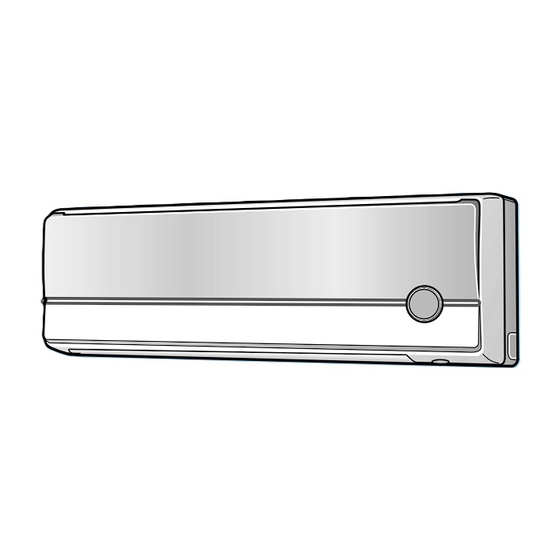
    ROOM AIR CONDITIONER INDOOR UNIT OUTDOOR UNIT SH09BPH SH09BPHX SH12BPH SH12BPHX Manual SERVICE AIR CONDITIONER CONTENTS 1. Product Specifications 2. Operating Instructions 3. Disassembly and Reassembly 4. Refrigerating Cycle Diagram 5. Set Up the Model Option 6. Troubleshooting 7. Exploded Views and Parts List 8.
  • Page 2: Product Specifications

    1. Product Specifications 1-1 Table Model SH09BPH SH12BPH SH09BPHX SH12BPHX Item Power Source ø-V-Hz 1-220/240-50 1-220/240-50 2,800(1,500~3,400) 3,500(1,500~4,000) Capacity BTU/h 9,500(5,100~11,600) 11,900(5,100~13,600) Energy Efficiency Ratio BTU/wh 11.8(10.0~13.8) 10.9(10.2~13.8) Cooling Air Flow /min Moisture Removal Noise Level Indoor Perfor- Noise Level...
  • Page 3 1-2 Pressure Graph SH09BPH 10.5 10.0 Outdoor Temp. (ßC) SH12BPH 10.5 10.0 Outdoor Temp. (ßC) Samsung Electronics...
  • Page 4: Operating Instructions

    The sleep timer can be used when you are cooling or heating your room to switch the air conditioner off automatically after a period of 6 hours. Anion button. Press the button to generate ion from the air conditioner. Samsung Electronics...
  • Page 5 After setting On Timer or Off Timer, press the button to set it completely. And press the button again to cancel On Timer or Off Timer set. Digital On/Off button. If you want to turn off the display during operation press the button. Samsung Electronics...
  • Page 6 Room Temperature Operating Mode Temperature Setting heat exchanger temperature and accumulating time of Less than 21˚C Heat 22˚C approx. compressor's operation. 21˚C or above Cool 24˚C approx. Deice ends by sensing of the processing time by deice condition. Samsung Electronics...
  • Page 7 The air conditioner can generate anion with an ionizer in the indoor unit. 13. BUZZER SOUND : Whenever the On/Off button is pressed or whenever change occurs to the condition which is set up or select, the compulsory operation mode, buzzer is sounded "beep". Samsung Electronics...
  • Page 8: Replace Pcb Model Option

    2-2 Replace PCB Model option 2-2-1 Replace PCB model option Remove power cord Replace the PCB module Check the connection and plug in Replace another PCB Does all display lamp blink? Refer to set up the Model option(15~17page) Samsung Electronics...
  • Page 9: Disassembly And Reassembly

    6) Loosen one of the right screw and detach the Terminal Cover. 7) Detach the thermistor from the Front Grille. 8) Loosen 5 fixing screws of Front Grille. 9) Pull the lower left and right of discharge softly for the outside cover to be pulled out. Samsung Electronics...
  • Page 10 Power Cord) (Main PCB) 2) Detach the outdoor unit connection wire from the Terminal Block. 3) If pulling the main PCB up, it will be taken out. 1) Pull Tray Drain out from the Back Body. Tray Drain Samsung Electronics...
  • Page 11 1) Loosen 2 fixing screws and separate the Fan Motor Motor Holder. & Cross Fan 2) Loosen 1 fixing screw of Fan Motor. (with a M3 wrench) 3) Detach the Fan Motor from the Fan. 4) Detach the Fan from the left Holder Bearing. Samsung Electronics...
  • Page 12 Cabinet-Side edge and a fixing screw on the Cabinet-Front lower to detach the Cabinet-Front. 2) Loosen 1 fixing screws of the Cover-Valve. 3) Loosen 6 fixing screws of the Cabinet-Side 4) Loosen 2 fixing screws of the Cabinet-Side Samsung Electronics...
  • Page 13 3) Disassemble the pipe in both inlet and outlet of the Compressor with welding torch. 4) Disassemble the pipe in both inlet and outlet of the Condenser with welding torch. 5) Loosen the 3 bolts at the bottom. 6) Detach the Compressor. Samsung Electronics...
  • Page 14: Refrigerating Cycle Diagram

    4. Refrigerating Cycle Diagram Outdoor Unit Indoor Unit Capillary tube 2-Way valve Liquid side Heat Heat Exchanger Exchanger (Evaporator) (Evaporator) Gas side 3-Way valve 4-Way valve Cooling Heating Compressor Gas leak check point Samsung Electronics...
  • Page 15: Set Up The Model Option

    . . . repeatedly. Push the button to set the display panel to Setting is not required if you must Every time you push the button, the display panel reads a value which has a default..repeatedly. Samsung Electronics...
  • Page 16 If all lamps of indoor unit are flickering, Plug out, plug in battery again and press ON/OFF key to retry. If the unit is not working properly or all lamps are continuously flickering after setting the option code, see if the correct option code is set up for its model. Samsung Electronics...
  • Page 17: Option Items

    Set up the Model Option OPTION ITEMS REMOCON SEG1 SEG2 SEG3 SEG4 SEG5 SEG6 SEG7 SEG8 SEG9 SEG10 SEG11 SEG12 MODEL SH09BPH SH12BPH Samsung Electronics...
  • Page 18: Troubleshooting

    The immediate operation starts Auto restart function is the convenient function where the operation state is without control of remote controller memorized in the Memory IC during the blackout and the operation restarts when when plugged the power comes back. Samsung Electronics...
  • Page 19 Temp-Sensor OLP temp-sensor Temp-Sensor Outdoor control PCB error Communication error between 2 micom on the outdoor PCB current sensor error heatsink temp-sensor error Voltage sensor error PCB, Outlet voltage Error display : and 2-digit-number are displayed alternately Samsung Electronics...
  • Page 20 CT sensor error Unit Over Current protection Deice sensor error(Open/Short) OLP sensor temp. trip OPTION error (EEPROM) Compressor rotation error DC fan error (SH12BWHX only) DC-Link voltage sensor error PFC OC error NO GAS error AC Line zero-crossing error Samsung Electronics...
  • Page 21 Check the outdoor unit In case of Error Code : Er/37(I), Er/38(K) In case of Error Code : Er/11(J), Er/12(M), Er/13(M), Er/14(L), Check the outdoor unit and In case of Error Code : Er/15(N), Er/18(O) outdoor unit installation Samsung Electronics...
  • Page 22 Take out the thermistor connected to the connector (CN41,CN42) of control board of indoor unit and measure the resistance between two wires and if it is same as follows: it is normal but if not, replace it. Ambient temperature 15°C 20°C 25°C 30°C 35°C 40°C (°C) Resistance of 14.68 12.09 8.31 6.94 5.83 thermistor [KΩ] Samsung Electronics...
  • Page 23 (PIN#3,4 of CN51 - discharge temperature sensor), (PIN#1,2 of CN52-OLP Temperature sensor) Measure the resistance between two wires and if it is same as follows, it is normal but if not, replace. Ambient temperature 0°C 10°C 20°C 30°C 40°C 50°C (°C) Resistance of thermistor [KΩ] Samsung Electronics...
  • Page 24 • R461 4.7K 6-3-10 (K) Check of Current sensor, Voltage sensor and Communication between 2 micom on the board. √ These errors are from component trouble on the outdoor control board. → Replace the outdoor control board √ Samsung Electronics...
  • Page 25 • If the comp is locked. → Replace the comp. • • If the comp is operating without the revolution of fan motor → Take out the protection cover. • → Check the fan motor connector and replace the fan motor. • Samsung Electronics...
  • Page 26 • Gas pressure balance is not good at stop condition. → Check service valve open. √ • → Check EEV motor attachement and connector. √ • √ • Compressor is locked or have some mechanical damage. → Replace the compressor. √ • Samsung Electronics...
  • Page 27 Check whether the wire of fan motor is connected to the control board (CN01) of outdoor unit. Check the voltage on the control board of outdoor unit and if it is same as follows, replace fan motor. Input power AC178V~AC264V. → CN01 1-3pin : DC250V±10% ~ DC370V±10% → CN01 4-3pin : DC15V Samsung Electronics...
  • Page 28: Fault Diagnosis Of Major Parts

    Approx. 290Ω at ambient temperature (20°C ~30°C) ∞, OΩ … open or short Abnormal Measure resistance between red wire and each terminal. Stepping Motor (FRONT GRILLE motor) Normal Approx. 110Ω at ambient temperature (20°C ~30°C) ∞, OΩ … open or short Abnormal Samsung Electronics...
  • Page 29: Exploded Views And Parts List

    Page 28 7. Exploded Views and Parts List 7-1 Indoor Unit 16-4 16-1 16-3 16-2 16-5 1-1-2 1-1-3 1-1-1 1-1-4 1-1-5 1-1-6 1-1-7 You can search for the updated part code number through the ITSELF. URL : http://itself.sec.samsung.co.kr Samsung Electronics...
  • Page 30 Exploded Views and Parts List Parts List Q'TY Code No. Description Specification Remark SH09BPH SH12BPH DB92-00488C ASS'Y PANEL FRONT-TOTAL ASS'Y DB92-00392F ASS'Y PANEL FRONT-SUB P ASS'Y 1-1-1 DB92-00346A ASS'Y PANEL FRONT ASS'Y 1-1-2 DB31-00166A MOTOR STEP 1-1-3 DB39-00794A CONNECTOR WIRE-STEP MOTOR...
  • Page 31 DB98_19047A(1)_2 4/21/04 2:27 PM Page 32 7-2 Outdoor Unit Samsung Electronics...
  • Page 32 DB63-01043A FELT COMP SIDE FELT G4C090LU1ER COMPRESSOR G4C090LU1ER DB99-00481B ASS'Y VALVE 4WAY ASS'Y DB97-02490B ASS'Y VALVE EEV ASS'Y DB71-00090E BAR-STEEL ASS'Y DB32-00083C ASS'Y THERMISTOR OUT ASS'Y DB32-00121A ASS'Y THERMISTOR OLP/SUC ASS'Y DB33-00021A SOLENOID-REACTOR 12A, 21mH 3301-001738 CORE-FERRITE ASS'Y Samsung Electronics...
  • Page 33 7-3 Ass'y Control In (Indoor Unit) SH09BPH / SH12BPH : DB93-02583A Samsung Electronics...
  • Page 34 DB39-00820A C/W ION-PCB ASS'Y DB61-01110A HOLDER-DISPLAY DB64-00763A HALF MIRROR 95,T1.5 2301-001339 FAN CAPACITOR 1.2 µF/450V DB72-00126N SEAL T3, FOAM-PE,GRAY DB32-00084B THERMISTOR OUT,ø6,220 DB32-00054B THERMISTOR IN,ø5,200 DB39-00183A C/W FAN_CAP UL1015 AWG #22 DB93-01549C POWER CORD 6001-001054 SCREW-MACHINE TH M4xL10 Samsung Electronics...
  • Page 35 7-4 Ass'y Control Out SH09BPHX : DB93-02740D SH12BPHX : DB93-02740C Samsung Electronics...
  • Page 36 INSULATOR-MICA DB65-00086A ASS'Y TERMINAL BLOCK 3P DB61-00250A HOLDER WIRE DB70-00465A PLATE-CASE CONTROL SGCC-MTO.6 6003-000325 SCREW-TAPPING PH,+,2,M3,L20 6005-000643 SCREW-TAPPING TH,+,1,M4,L10 6002-000171 SCREW-TAPPING PH,+,2S,M4,L10 FOAMLEX 60x180xT2.0 DB93-00936A RUN CAPACITOR 1.7µF/450V SCREW-TAPPING M3x14 WSP PH+ DB62-02541L SEAL CASE CONTROL BASE 70x15xT10 Samsung Electronics...
  • Page 37: Pcb Diagram

    8. PCB Diagram 8-1 ASS'Y PCB Indoor Unit : DB93-02584A Samsung Electronics...
  • Page 38 PCB Diagram BOTTOM Samsung Electronics...
  • Page 39 R606 R-CHIP 560ohm,5%,1/10W,TP,1068 R706 R-CHIP 100Kohm,5%,1/8W,TP,2012 R202,R203,R304,R205 R-CHIP 100Kohm,5%,1/4W,TP,3216 R707 R-CHIP 1Kohm,5%,1/8W,TP,2012 R102,R103,R104 R-CHIP 220Kohm,5%,1/4W,TP,3216 R106,R407 R-CHIP 220ohm,5%,1/8W,TP,2012 R101 R-CHIP 4.7Kohm,5%,1/8W,TP,2012 R105 R-CHIP 470ohm,5%,1/8W,TP,2012 R402,R501,R502,R503 R-CHIP 6.8Kohm,1%,1/10W,TP,1068 R303 R-CHIP 8.2Kohm,1%,1/10W,TP,1068 C104 C-CERAMIC,DISC 2.2NF,20%,400V,Y5U,BK,12.5x6mm,10 C103,C107,C110,C112,C201 C-CER,CHIP 100nF,+80-20%,50V,Y5V,TP,2012 C202,C500,C501,C502,C503 C901 Samsung Electronics...
  • Page 40 CN51 CONNECTOR-HEADER BOX,14P,1R,2mm,STRAIGHT,SN CN53 CONNECTOR-HEADER BOX,3P,1R,2mm,STRAIGHT,SN CN61 CONNECTOR-HEADER PH-5A,BOX,5P,2mm,WHT CN41 CONNECTOR-HEADER BOX,4P,1R,2mm,STRAIGHT,SN,WHT CN81 CONNECTOR-HEADER PH-3A,BOX,3P,1R,2mm,BLU IC02 KA78L05AZTA(0.1A,Positive,Vol,Reg) IC04 IC MICOM MB89538APF-101,MB89538APF-101,64P,+5V,10M ST11 TRANS SWITCHING DC12V,-,-,-,-,-,-,12V,0.01A,-,E119 POSISTOR DSA-332MA,2pF MAX,100Mohm,ASM-3 LEAD-WIRE UL1015 AWG#20 GRN/YEL FT72 LS403110 C001 SC102M Y-CAP 7.5mm Samsung Electronics...
  • Page 41 8-2 Ass'y PCB Outdoor Unit : DB93-02741D(9K) / DB93-02741C(12K) Samsung Electronics...
  • Page 42 FT01 SS2915044B SS2915044B FT00 SS2915025B SS2915025B FUSE FUSE 65TS-150-H,250V,20A IC01 IC-MICOM ML66Q517 IC11 IC-PWM CONTROLLER TOP222P,8P/DIP IC17 IC-POSI.FIXED REG KA7805A,TO-220 IC18 IC-POSI.FIXED REG KA7815 IC19 IC-POSI.FIXED REG KA7812A,TO-220 IC21,IC32 PHOTO-COUPLER TLP181-GRH,150-300% IC701 IC-EEPROM 93LC56,128x16Bit IC73 IC-POSI.ADJUST REG TL431,8P/SMD Samsung Electronics...
  • Page 43 10K-F,1/12W,1608 R531,R525,R524,R522,R521,R533,R534 R535 R536 R-CHIP 1M-J,1/10W,1608 R537,R538 R-CHIP 10K-J,1/10W,1608 R801 R-CEMENT 0.045-J,3W R812,R506,R517,R505,R553 R-CHIP 330-J,1/12W,1608 RY01 RELAY-POWER UKH-12S,12Vdc/20A RY502,RY501 RELAY-MINIATURE FTR-F3AA012E,12Vdc/5A VA07,VA08,VA09,VA03,VA04 VARISTOR INR14D561K-RS,560V,2500A XTAL01 RESONATOR-CERAMIC 6.25MHz, * ZD21 DIODE-ZENER 1N4749A,24V/1W ZD23,ZD22 DIODE-ZENER MMBZ5232B, * ZD31 DIODE-ZENER 1N4751A,30V/1W Samsung Electronics...
  • Page 44 PCB Diagram BOTTOM Samsung Electronics...
  • Page 45 R-CHIP 6.8K-F,1/8W,2012 R110,R111,R451 R-CHIP 180K-F,6432/1W R112,R113,R114 R-CHIP 470K-F,1/4W R203,R405,R461,R804 R-CHIP 4.7K-J,1/8W,2012 R407,R408,R409 R-CHIP 33-J,1/10W,2012 R104,R106,R413 R-CHIP 3.3K-J,1/8W,2012 R414,R523,R532,R808,R810 R-CHIP 10K-F,1/10W,2012 R416 R-CHIP 390-J,1/10W,2012 R419,R420,R422,R424 R-CHIP 100-J,1/8W,2012 R426,R427,R428 R-CHIP 300K-F,1W,6432 R429 R-CHIP 1.6K-F,1/8W,2012 R430 R-CHIP 51-F,1/8W,2012 R452 R-CHIP 150K-F,1W,6432 Samsung Electronics...
  • Page 46 5.1K-F,1/8W,2012 R539,R540,R541 R-CHIP 2.2K-J,1/8W,2012 R502,R552 R-CHIP 24K-F,1/8W,2012 R554 R-CHIP 470-J,1/8W,2012 R802 R-CHIP 220-J,1/8W,2012 R803 R-CHIP 2.2K-F,6432/1W R805 R-CHIP 3.3K-F,1/8W,2012 R302,R807 R-CHIP 1K-J,1/8W,2012 R103,R811,R813 R-CHIP 330-J,1/8W,2012 R814 R-CHIP 5.1K-J,1/8W,2012 R806,R809,R901,R902, R-CHIP 10K-J,1/8W,2012 R903,R904,R905,R908 R906 R-CHIP 6.8K-J,1/8W,2012 R907 R-CHIP 560-J,1/8W,2012 Samsung Electronics...
  • Page 47 8-3 ASS'Y DISPLAY PCB(9K / 12K) : DB93-01368G Parts List Description Specification Q'TY Remark ASS'Y LED MODULE PCB-DISPLAY FR-1 T1.6 TACT SWITCH KPT-1105A TSTA-2 RESISTOR 200ohm, 2W RESISTOR 100ohm, 2W CONNECTOR WIRE Samsung Electronics...
  • Page 48 8-4 ASS'Y MODULE PCB(9K / 12K) : DB93-01369A Parts List Description Specification Q'TY Remark PCB-DISPLAY FR-1 T1.6 CONNECTOR SMAW200-03P(WHT) C-CERAMIC CA OA 50V 102K DIODE SWITCHING 1N4148 C-CERAMIC CA OA 50V 104Z MODULE REMOCON FRP4021-H7(7mm) Samsung Electronics...
  • Page 49: Wiring Diagram

    DB98_17175A_1 2/6/04 4:14 PM Page 49 9. Wiring Diagram 9-1 Indoor Unit(9K / 12K) This Document can not be used without Samsung's authorization. Samsung Electronics...
  • Page 50 DB98_19047A(1)_2 4/21/04 2:27 PM Page 50 9-2 Outdoor Unit(9K / 12K) Code No : DB98-17635A This Document can not be used without Samsung's authorization. Samsung Electronics...
  • Page 51 MEMO Samsung Electronics...
  • Page 52 ELECTRONICS © Samsung Electronics Co., Ltd. This Service Manual is a property of Samsung Electronics Co., Ltd. Any unauthorized use of Manual can be punished under applicable Printed in China. International and/or domestic law.

This manual is also suitable for:

Sh12bphSh09bphxSh12bphx

Table of Contents