Table of Contents
Advertisement
SERVICE
AIR CONDITIONER
ROOM AIR CONDITIONER
AQ12 5(6)MB
AQ12 A(B)ME
AQ12 5(6)ME
AQ09 5(6)MED
AQ09 5(6)ME
AQ07 5(6)MED
SH09Z 5(6)
SH12Z A(B)
AQ07 5(6)ME
SH09Z 5(6)D
SH07Z 5(6)
SH07Z 5(6)D
AQ09 7(8)ME
SH09Z 7(8)
AQ07 7(8)ME
SH07Z 7(8)
AQ12 9(0)ME
SH12Z 9(0)
Manual
3.
Installation
UQ12 5(6)MB
UQ12 A(B)ME
UQ12 5(6)ME
UQ09 5(6)ME
SH12Z A(B)X
UQ07 5(6)ME
UQ09 7(8)ME
UQ07 7(8)ME
SH07Z 7(8)X
UQ12 9(0)ME
SH12Z 9(0)X
CONTENTS
Advertisement
Table of Contents

Related Manuals for Samsung AQ12?5(6)MB


Summary of Contents for Samsung AQ12?5(6)MB
-
Page 1: Room Air Conditioner
ROOM AIR CONDITIONER INDOOR UNIT OUTDOOR UNIT AQ12 5(6)MB AQ12 A(B)ME UQ12 5(6)MB UQ12 A(B)ME AQ12 5(6)ME UQ12 5(6)ME UQ09 5(6)MED AQ09 5(6)MED AQ09 5(6)ME UQ09 5(6)ME UQ07 5(6)MED AQ07 5(6)MED SH09Z 5(6) SH09Z 5(6)X SH12Z A(B)X SH12Z A(B) AQ07 5(6)ME UQ07 5(6)ME SH09Z 5(6)DX SH09Z 5(6)D... - Page 2 Relocate the unit if necessary. 9. Keep children away from the unit while it is being repaired. Fig. 1-3 No Kids Nearby! 10. Be sure to clean the unit and its surround- ing area. Fig. 1-4 Clean the Unit Samsung Electronics...
-
Page 3: Product Specifications
Refrigerant to change(R-22) Protection device MRA 12002-9200/MRA 12002-12008 MRA 12030-12008/RAC12030-9622 RAC 12054-9622 Cooling test Condition INDOOR UNIT : DB27°C WB19°C OUTDOOR UNIT : DB35°C WB24°C Maximum operation Condition INDOOR UNIT : DB32°C WB23°C OUTDOOR UNIT : DB43°C WB26°C Samsung Electronics... -
Page 4: Samsung Electronics
2ROW 20STEP CAPILLARY TUBE CAPILLARY TUBE CAPILLARY TUBE CAPILLARY TUBE RAC 12086-9622 MRA 12110-12008/RAC12054-9622 MRA 12086-12008/RAC12086-9622 MRA 12030-12008/RAC12030-9622 INDOOR UNIT : DB27°C WB19°C OUTDOOR UNIT : DB35°C WB24°C INDOOR UNIT : DB32°C WB23°C OUTDOOR UNIT : DB43°C WB26°C Samsung Electronics... - Page 5 Freezer oil capacity Refrigerant to change(R-22) 1000 Protection device RAC12030-9622 RAC 12054-9622 RAC 12086-9622 Cooling test Condition INDOOR UNIT : DB27°C WB19°C OUTDOOR UNIT : DB35°C WB24°C Maximum operation Condition INDOOR UNIT : DB32°C WB23°C OUTDOOR UNIT : DB43°C WB26°C Samsung Electronics...
- Page 6 2-2 Dimensions 2-2-1 Indoor Unit (Front view) Air in Air out (Remote Control) (Rear view) Installation plate Samsung Electronics...
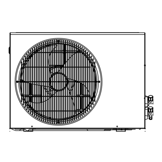
- Page 7 2-2-2 Outdoor Unit UQ12 5(6)M (Front view) (Rear view) UQ09 5(6)M UQ07 5(6)M SH09Z 5(6)X SH07Z 5(6)X UQ09 5(6)M D UQ07 5(6)M D SH09Z 5(6)DX SH07Z 5(6)DX SH07Z 7(8)X SH09Z 7(8)X UQ07 7(8)M UQ09 7(8)M Samsung Electronics...
- Page 8 Product Specifications UQ12 9(0)M SH12Z 9(0)X UQ12 A(B)ME SH12Z A(B)X Samsung Electronics...
-
Page 9: Pressure Graph
2-3 Pressure Graph 12K BTU 32.4/24.0 30.6/22.5 28.8/21.0 27.0/19.0 24.0/17.0 21.5/15.0 9K BTU 32.4/24.0 30.6/22.5 28.8/21.0 27.0/19.0 24.0/17.0 21.5/15.0 7K BTU 32.4/24.0 30.6/22.5 28.8/21.0 27.0/19.0 24.0/17.0 21.5/15.0 Samsung Electronics... -
Page 10: Operating Instructions
To select the 5 way function with the remote control, press the 5 way button one or more times until the desired mode is selected. Each time you press the 5 way button. Each 5 way indicator on the indoor unit comes on in order. Samsung Electronics... - Page 11 De-ice ends by sensing of the processing time by de-ice Condition. 7. FAN SPEED : Manual (3 step), Auto (4 step) Fan speed automatically varies depending on both the difference between setting and the room temperature. Samsung Electronics...
- Page 12 ON at a specified time using OFF TIMER : The air Conditioner is turned OFF at a specified time using *ON TIMER : Only timer LED lights on. *OFF TIMER : Both timer and operation LED lights on. Samsung Electronics...
- Page 13 MEMO Samsung Electronics...
-
Page 14: Disassembly And Reassembly
7) Pull the upper left and right of discharge softly for the outside cover to be pulled out. 8) Pull softly the lower part of discharge and push it up. Caution; Assemble the front panel and fix the hooks of left and right. Samsung Electronics... - Page 15 4) Separate the holder pipe at the rearside. 5) Loosen the three fixing screws of right and left side. 6) Lifting the heat exchanger up a little to push the up side for separation from the indoor unit. Samsung Electronics...
- Page 16 2) Loosen the fixing two screws and separate the motor holder. 3) Loosen the fixing screw of fan motor. (By use of M3 wrench) 4) Separate the fan motor from the fan. 5) Separate the fan from the left holder bearing. Samsung Electronics...
-
Page 17: Outdoor Unit
Handle-Cabi RH. 2) Separate the connection wire from the terminal block. 3) Loosen 6 fixing screws and separate the upper cabinet. 4) Loosen the fixing screw of Ass'y E-part. 5) Loosen 5 fixing screws and separate the side cabinet. Samsung Electronics... - Page 18 1) Loosen 4 fixing screw of the Guard-Fan. 2) Remove the nut flange (Turn to the right to remove, as it is a left hand screw) 3) Separate the fan. 4) Loosen four fixing screws to separate the motor. Samsung Electronics...
- Page 19 Upper. 4) Loosen two fixing screws of Ass'y E-part. 5) Loosen nine fixing screws and separate the cabi side. Fan and Motor 1) Do “1”, above. 2) Loosen four screws and seperaate Guard Fan from front cabinet. Samsung Electronics...
- Page 20 3) Disassemble the inlet and outlet pipe of com- pressor by welding. 4) Disassemble the inlet and outlet pipe of con- denser by welding. 5) Loosen the three bolts of the lower part. 6) Separate the compressor. Samsung Electronics...
- Page 21 3) Separate the connection wire from the terminal block. 4) Loosen six fixing screws and separate the cabi front. 5) Loosen the one fixing screw of Ass'y E-part. 6) Loosen 12 fixing screws and separate the cabi side. Samsung Electronics...
- Page 22 1) Do “1”, “2”, “3” above. 2) Open the terminal cover of compressor and unscrew the connection terminal. 3) Disassemble the inlet and outlet pipe of compressor by welding. 4) Loosen the three bolts of the lower part. 5) Separate the compressor. Samsung Electronics...
- Page 23 Upper. 4) Loosen two fixing screws of Ass'y E-part. 5) Loosen seven fixing screws and separate the cabi side. Fan and Motor 1) Do “1”, above. 2) Losen four serews and seperaate Guard Fan from front cabinet. 4-10 Samsung Electronics...
- Page 24 3) Disassemble the inlet and outlet pipe of compressor by welding. 4) Disassemble the inlet and outlet pipe of condenser by welding. 5) Loosen the three bolts of the lower part. 6) Separate the compressor. Samsung Electronics 4-11...
- Page 25 3) Separate the connection wire from the terminal block. 4) Loosen 13 fixing screws and separate the cabi front. 5) Loosen the one fixing screw of Ass'y E-part. 6) Loosen 4 fixing screws and separate the cabi side. 4-12 Samsung Electronics...
- Page 26 Compressor 2) Open the terminal cover of compressor and unscrew the connection terminal. 3) Disassemble the inlet and outlet pipe of compressor by welding. 4) Loosen the three bolts of the lower part. 5) Separate the compressor. Samsung Electronics 4-13...
- Page 27 MEMO 4-14 Samsung Electronics...
-
Page 28: Troubleshooting
Indoor unit Room sensor Error (open or short) 3 STD and TIMER LED blinking (1Hz) Indoor unit heat exchanger temperature sensor Error (open or short) 4 NATURE LED blinking (1Hz) Indoor fan malfunctioning (for spead is Below 450rpm) Samsung Electronics... -
Page 29: Fault Diagnosis By Symptom
Check PCB pattern. Replace ICO2 Replace main PCB. 10ms Is voltage output terminal of PC814(PC02) normal? Are voltage at #11 and #12 of the micom normal? Replace resonator (X301) 250ns Replace PC814(pc02) Is operation normal? Replace micom Samsung Electronics... -
Page 30: When The Indoor Unit Fan Does Not Operate. (Initial Diagnosis)
Test rod location Normal voltage PCB CN72 Condition Fan operate about AC 180V pin #3 and #5 MF-C is out of order Replace MFC Fan motor Fan motor should be replaced. is out of order. Samsung Electronics... -
Page 31: When The Outdoor Unit Does Not Operate. (Initial Diagnosis)
Power relay should be Is rating voltage ±10% range applied relay between Terminal block out of order replaced. NO(N1) and No. 1 Outdoor unit is out of order. Is the room sensor normal register? 10°C 20°C 30°C 17.96kΩ 12.09kΩ 8.3kΩ Samsung Electronics... - Page 32 Is the voltage between CN71 #3 and CN71 #5 rating voltage ±10% range Abnormal RY73 Abnormal 4way valve of Outdoor Unit. or connecting Cable PCB should be replaced. 4 way valve should be replaced or connecting Cable Check. Samsung Electronics...
-
Page 33: If Operation By Remote Control Unit Is Impossible. (Initial Diagnosis)
Voltage at PIN #30 of Remocon Micom change? Voltage at collecter of Q601 or Q602 change? Q601(C4375Y) or Q602(C1623Y) is faulty. IR LED(CL-1L5EU) is faulty. Voltage at pin #26 of micom (IC04) change (INDOOR UNIT)? Receiver module is faulty. Micom (IC04) is faulty. Samsung Electronics... - Page 34 5-3-2 Procedure The parts should be replaced in the following procedure. Check for any faulty part. Detach the faulty part. Replace it with a new part. Check the operation of the new part. The repair is completed. Samsung Electronics...
- Page 35 Voltage check SMPS circuit is faulty 1. check voltage of IC06 IC06 is faulty (pin#10,pin#8) Set the TURBO mode : relay on 0.7[v] : relay off 12[v] 2. Voltage at terminal block RY71 is faulty ((N1) -1) rating voltage Samsung Electronics...
-
Page 36: Fault Diagnosis Of Major Parts
Black, White 257±10% ∞, OΩ … open or short Abnormal Measure resistance between red wire and each terminal. Stepping Motor Normal Approx. 380Ω at ambient temperature (20°C ~30°C) (UP/DOWN swing motor) ∞, OΩ … open or short Abnormal Samsung Electronics... -
Page 37: Set Up The Model Option
$ When pressing the button appear on the display, select one of them. % When pressing the button appear on the display, select one of them. ^ When pressing the button appear on the display, select one of them. 5-10 Samsung Electronics... - Page 38 If all lamps of indoor unit are flickering, Plug out and plug in again and pressing ON/OFF key to retry. If the unit is not working properly or all lamps are continuously flickering after setting the option code, see if the correct option code is set up for it’s model. Samsung Electronics 5-11...
- Page 39 SH07Z 6 / SH07Z 6D AQ09 7ME 016825-1700d9 SH09Z 7 AQ09 8ME 006825-1700d9 SH09Z 8 AQ07 7ME 014825-170067 SH07Z 7 AQ07 8ME 004825-170067 SH07Z 8 AQ12 9ME 017d25-17021d SH12Z 9 AQ12 0ME 007d25-17021d SH12Z 0 AQ12 A(B)ME 007227-17023F SH12Z A(B)X 5-12 Samsung Electronics...
- Page 40 6. Exploded Views and Parts List 6-1 Indoor Unit 18-6 18-6-1 18-1 18-4 18-5 18-3 18-2 13-2 13-3 13-4 13-1 You can search for the updated part code number through the ITSELF. URL : http://itself.sec.samsung.co.kr Samsung Electronics...
- Page 41 BLADE V,B OPTION 18-5 DB63-00082A SCREEN SAFETY WIRE 18-6 DB95-20138A ASS´Y MOTOR STEPPING 18-6-1 DB31-10129A MOTOR STEPPING; GSP 24RW DB61-40251A HOLDER SENSOR DB67-60030A SPRING SENSOR DB96-00784A EVAPORATOR ASS´Y DB96-00783A EVAPORATOR ASS´Y DB94-40003A RUBBER BEARING DB94-40007A BEARING DB93-00251L ASS´Y REMOCON Samsung Electronics...
- Page 42 BLADE V,B OPTION 18-5 DB63-00082A SCREEN SAFETY WIRE 18-6 DB95-20138A ASS´Y MOTOR STEPPING 18-6-1 DB31-10129A MOTOR STEPPING; GSP 24RW DB61-40251A HOLDER SENSOR DB67-60030A SPRING SENSOR DB96-01366A EVAPORATOR ASS´Y DB96-01443A EVAPORATOR ASS´Y DB94-40003A RUBBER BEARING DB94-40007A BEARING DB93-00251L ASS´Y REMOCON Samsung Electronics...
- Page 43 6-2 Outdoor Unit(UQ12 5(6)MB(E)) Samsung Electronics...
- Page 44 HEX 2C MB ZPC DB63-20002A GASKET EPDM DB63-10165D COVER TERMINAL DB60-30018A NUT-FLANGE M5, SM20C DB96-00513A ASS´Y-CAPILLARY ASS’Y(1.7x1100) DB99-00085A ASS´Y-CHECK VALVE ASS’Y (C=1.7x1200 H=1.5x300) DB96-00509A ASS´Y COND ASS’Y(SF) DB64-00136B CABINET SIDE ASS’Y(BENDING) DB67-90025A HANDLE CABI, RH DB72-00211A CLOTH-COMP SIDE FELT Samsung Electronics...
- Page 45 Outdoor Unit • UQ07 5(6)ME UQ07 5(6)MED • SH07Z 5(6)X SH07Z 5(6)DX • UQ09 5(6)ME UQ09 5(6)MED • SH09Z 5(6)X SH09Z 5(6)DX Samsung Electronics...
- Page 46 C3771BD, 432L/H, 3/8”, 30Kg/cm DB75-00029A ASS´Y COND 1.5D-FIN, COATTING 620mm DB96-01286A ASS´Y COND 1.5LOUVER, COATTING 636mm DB64-60171B CABINET-SIDE SECC-P, T 0.8, A-P/J DB64-60171C CABINET-SIDE SECC-P, T 0.8, A-P/J DB67-90024A HANDLE-CABI LF DB67-00171A HANDLE-CABI LF DB63-10443C COVER-E, PARTS ASS’Y SC-90073R Samsung Electronics...
- Page 47 Outdoor Unit • SH07Z 7(8)X/UQ07 7(8)ME • SH09Z 7(8)X/UQ09 7(8)ME Samsung Electronics...
- Page 48 Single OLP 13-3 DB61-00174A HOLDER CAPACITOR 13-4 DB65-40049D TERMINAL BLOCK;4P 13-5 2301-001375 C OIL;1.5µF, 450VAC DB90-00108C ASS´Y CABI FRONT 14-1 DB63-00099A GUARD FAN WIRE 14-2 DB61-00173A GUIDE BELL MOUTH DB90-00152A ASS´Y COVER CONTROL DB94-00021A ASS´Y COVER VALVE DB90-00195A ASS’Y-CAPILLARY Samsung Electronics...
- Page 49 Outdoor Unit • UQ12 9(A0)ME • SH12Z 9(A0)X 6-10 Samsung Electronics...
- Page 50 DB67-50063A FAN-PROPELLER AS+G/F20%, PI 405, BLK DB31-10058C MOTOR-FAN OUT AMASS-020WTVA, FAN OUT, 220/240 DB90-00372A ASS´Y FRAME V2 P/D, 48F, SAMSUNG, SILK DB72-00194J SEAL-FRONT, RH 30FOAM-PU, T15, 15, 400, BLK DB94-00098A ASS´Y PARTITION V2 P/D, 12K, 2ROW COND DB90-00374A ASS´Y CABI-UPPER...
- Page 51 Outdoor Unit • UQ12 A(B)ME • SH12Z A(B)X 6-12 Samsung Electronics...
- Page 52 NUT-WASHER HEX 2C MB ZPC DB63-20002A GASKET EPDM DB63-10165D COVER TERMINAL DB60-30018A NUT-FLANGE M5, SM20C DB99-00157B ASS´Y CHECK V/V ASS’Y(1.5x700/1.5x500) DB96-01461A ASS´Y COND ASS’Y(SF) DB90-00634A CABINET SIDE ASS’Y(BENDING) DB63-10443C HANDLE CABI, RH DB61-00802A BRACKET MOTOR SGCC-M, T1.2 Samsung Electronics 6-13...
- Page 53 6-3 Remote Control & PCB Box 6-3-1 ASS’Y REMOCON : DB93-00251L Parts List Description Q’TY Remark INLAY LCD CASE TOP KEY RUBBER ASS’Y PCB REMOCON CASE LOW BATTERY COVER 6-14 Samsung Electronics...
- Page 54 ASS’Y TERMINAL BLOCK ASS’Y DISPLAY PCB ASS’Y CONNECTOR WIRE PCB U/D HOLDER WIRE CLAMP SCREW PH, M3 5 L22 SCREW TH + M4 5 x16, ZPC(WHT), SWRCH HOLDER CLAMP IN SEAL PANEL FRONT RH SEAL H/CONTROL FRONT Samsung Electronics 6-15...
- Page 55 MEMO 6-16 Samsung Electronics...
-
Page 56: Block Diagrams
7. Block Diagrams 7-1 Refrigerating Cycle Block Diagram UQ12 5(6)MB, UQ12 9(0)ME use only Note Note UQ12 5(6)ME(B)/SH12Z 5(6)X - The check valve is applied only to UQ12 9(0)ME(B)/SH12Z 9(0)X as below UQ12 A(B)ME(B)/SH12Z A(B)X Samsung Electronics... - Page 57 MEMO Samsung Electronics...
- Page 58 8. PCB Diagrams 8-1 ASS’Y MAIN PCB;DB93-00437A TOP PATTERN Samsung Electronics...
- Page 59 R402 R-CHIP MCR10EZHJ472 R108, R603, R901 R-CHIP MCR10EZHJ102 R201, R207, R208, R301, R401, R403, R408, R601, R607, R608 R-CHIP MCR10EZHJ561 R606 R-CHIP MCR10EZHJ471 R105, R604, R605 R-CHIP MCR10EZHJ331 R405, R407 R-CHIP MCR10EZHJ221 R106, R107 RELAY-MINIATURE F3AA012E RY72, RY73 Samsung Electronics...
- Page 60 PCB Diagrams BOTTOM PATTERN Samsung Electronics...
- Page 61 8-2 ASS’Y MAIN PCB;DB93-01017A TOP PATTERN Samsung Electronics...
- Page 62 R402 R-CHIP MCR10EZHJ472 R108, R603, R901 R-CHIP MCR10EZHJ102 R201, R207, R208, R301, R401, R403, R408, R601, R607, R608 R-CHIP MCR10EZHJ561 R606 R-CHIP MCR10EZHJ471 R105, R604, R605 R-CHIP MCR10EZHJ331 R405, R407 R-CHIP MCR10EZHJ221 R106, R107 RELAY-MINIATURE F3AA012E RY72, RY73 Samsung Electronics...
- Page 63 PCB Diagrams BOTTOM PATTERN Samsung Electronics...
- Page 64 64.5x53 LED-LAMP LD01,LD02,LD03,LD04,LD05 SO5511 LED-LAMP LD06 SY5511 MODULE REMOCON IRM01 KSM-713TH5 DIODE SWITCHING IN4148 R-CARBON R01,R02,R03 470 1/2W 5% CONNECTOR WIRE C/W-DISPLAY SMAW200-10P TACT SWITCH SW01 KPT-1105A C-CERAMIC 104Z C-CERAMIC 102K JUMP JP-1,JP02 10mm COVER DISPLAY UP ABS(V2) Samsung Electronics...
- Page 65 MEMO Samsung Electronics...
-
Page 66: Wiring Diagrams
9. Wiring Diagrams 9-1 Indoor Unit Samsung Electronics... - Page 67 9-2 Outdoor Unit • UQ 5(6) 09(0) DIAGRAM-OUTDOOR C1 : MOTOR CAPACITOR DB68-01624A C2 : COMP CAPACITOR • UQ 7(8) / SH Z 7(8)X DIAGRAM-OUTDOOR C1 : MOTOR CAPACITOR DB68-01765A C2 : COMP CAPACITOR Samsung Electronics...
- Page 68 MEMO Samsung Electronics...
- Page 69 10. Schematic Diagrams 10-1 Indoor Unit 10-1 Samsung Electronics Samsung Electronics 10-2...
- Page 70 MEMO 10-3 Samsung Electronics...
- Page 71 Itself Solution Integrated technology supporting electronic library http://itself.sec.samsung.co.kr Copyright © 2002 By Samsung Electronics Co., Ltd. All rights reserved. This manual may not, in whole or in part, be copied, photocopied, reproduced, translated, or converted to any electronic or machine readable from without prior written permission of Samsung Electronics Co., Ltd.
- Page 72 ELECTRONICS © Samsung Electronics Co., Ltd. Mar. 2002. Printed in Korea. Code No. DB81-00181A(4)
Need help?
Do you have a question about the AQ12?5(6)MB and is the answer not in the manual?
Questions and answers