Table of Contents
Advertisement
RETURN TO MAIN MENU
SVM140-A
July, 2005
™
PRO-CUT
55
For use with machine code numbers Below 11000
Safety Depends on You
Lincoln arc welding and cutting
equipment is designed and built
with safety in mind. However,
your overall safety can be
increased by proper installation
. . . and thoughtful operation on
your part. DO NOT INSTALL,
OPERATE OR REPAIR THIS
EQUIPMENT WITHOUT READ-
ING THIS MANUAL AND THE
SAFETY PRECAUTIONS CON-
TAINED THROUGHOUT. And,
most importantly, think before
you act and be careful.
SERVICE MANUAL
Copyright © 2005 Lincoln Global Inc.
• World's Leader in Welding and Cutting Products •
• Sales and Service through Subsidiaries and Distributors Worldwide •
Cleveland, Ohio 44117-1199 U.S.A. TEL: 216.481.8100 FAX: 216.486.1751 WEB SITE: www.lincolnelectric.com
Advertisement
Chapters
Table of Contents
Troubleshooting

Related Manuals for Lincoln Electric PRO-CUT 55 SVM140-A


Summary of Contents for Lincoln Electric PRO-CUT 55 SVM140-A
-
Page 1: Service Manual
RETURN TO MAIN MENU SVM140-A July, 2005 ™ PRO-CUT For use with machine code numbers Below 11000 Safety Depends on You Lincoln arc welding and cutting equipment is designed and built with safety in mind. However, your overall safety can be increased by proper installation . -
Page 2: Electric Shock Can Kill
WARNING PROTECT YOURSELF AND OTHERS FROM POSSIBLE SERIOUS INJURY OR DEATH. KEEP CHILDREN AWAY. PACEMAKER WEARERS SHOULD CONSULT WITH THEIR DOCTOR BEFORE OPERATING. Read and understand the following safety highlights. For additional safety information it is strongly recommended that you pur- chase a copy of “Safety in Welding &... - Page 3 4.g. Sparks and spatter are thrown from the plasma arc. Wear safe- ty glasses, ear protection and oil free protective garments such as leather gloves, heavy shirt, cuffless trousers, high shoes and a cap over your hair. Wear ear plugs when cutting or goug- ing out of position or in confined places.
- Page 4 NOTES PRO-CUT 55...
-
Page 5: Table Of Contents
MASTER TABLE OF CONTENTS FOR ALL SECTIONS Safety ...i-iii Installation ...Section A Operation...Section B Accessories...Section C Maintenance ...Section D Theory of Operation ...Section E Troubleshooting and Repair...Section F Safety Precautions ...F-2 How to Use Troubleshooting Guide...F-2 Troubleshooting Guide ...F-4 Test Procedures ...F-14 Replacement Procedures ...F-50 Electrical Diagrams ...Section G Parts Manual ...P309 Series &... - Page 6 Section A-1 - INSTALLATION SECTION - Installation Technical Specifications ...A-2 Safety Precautions...A-4 Select Suitable Location...A-4 Stacking ...A-4 Lifting and Moving ...A-4 Tilting ...A-4 High Frequency Interference Protection...A-4 Input Electrical Connections...A-5 Ground Connection ...A-5 Input Power Cord Connector Installation ...A-5 Input Wire and Fuse Size ...A-5 Reconnect Procedure...A-6 Gas Input Connections...A-7 Output Connections ...A-8...
-
Page 7: Installation
TECHNICAL SPECIFICATIONS - PRO-CUT 55 Single Phase Input Voltage and Hertz 208/1/60 230/1/60 460/1/60 208/1/60 230/1/60 460/1/60 Three Phase Input Voltage and Hertz 208/3/60 230/3/60 460/3/60 208/3/60 230/3/60 460/3/60 IDLE CURRENT AND WATTS 230/1/60 Duty Cycle 100% Current Range 25 - 55 Amps INSTALLATION INPUT RATINGS Input Currents... -
Page 8: Physical Dimensions
TECHNICAL SPECIFICATIONS (Cont’d) - PRO-CUT 55 Required Gas Flow Rate 70 PSI @ 360 SCHF (4.8 Bar. @ 10160 LHR) (6 CFM) RECOMMENDED INPUT WIRE AND FUSE SIZES For all plasma cutting applications based on U.S. National Electrical Code AC Input Voltage Fuse (Super Lag) Circuit Breaker 60 Hertz... -
Page 9: Safety Precautions
Read this entire installation section before you start installation. SAFETY PRECAUTIONS WARNING ELECTRIC SHOCK can kill. • Turn the input power OFF at the disconnect switch or fuse box and discharge input capacitors before working inside the equip- ment. • Do not touch electrically hot parts or electrodes with your skin or wet clothing. -
Page 10: Input Electrical Connections
INPUT CONNECTIONS WARNING ELECTRIC SHOCK can kill. • Have a qualified electrician install and service this equipment. • Turn the input power off at the fuse box before working on this equipment. • Do not touch electrically hot parts. Before installing the machine, check that input supply voltage, phase, and frequency are the same as the machine’s voltage, phase, and frequency as specified on the machine’s rating plate. -
Page 11: Reconnect Procedure
RECONNECT PROCEDURE When received directly from the factory, the machines are internally connected for 230 VAC. Reconnection will be necessary if a higher input voltage is used. To reconnect the Pro-Cut to 460 VAC or to connect back to 230 VAC, follow the directions as outlined below. Follow this procedure ONLY while the Pro-Cut is dis- connected from the input power. -
Page 12: Gas Input Connections
GAS INPUT CONNECTIONS Supply the Pro-Cut 55 with clean compressed air or nitrogen. • Supply pressure must be between 80 psi and 150 psi. • Flow rate should be approximately 6.0 cfm (170 I/min.). NOTE: Oil in the air supply to the Pro-Cut 55 can cause severe problems. -
Page 13: Output Connections
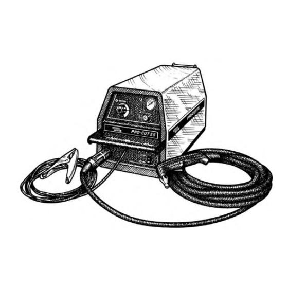
INSTALLATION OUTPUT CONNECTIONS FIGURE A.4 - TORCH CONNECTION AT CASE FRONT TORCH CONNECTION The Pro-Cut 55 is supplied from the factory with a PCT 80 cutting torch. Additional cutting torches can be XXXX XXXX XXXX XXXX ordered from the K1571 series. Hand-held and mech- anized torches come with 25 or 50 foot cables. -
Page 14: Operation Section
Section B-1 - OPERATION SECTION - Operation...Section B Safety Instructions ...B-2 General Description ...B-3 Recommended Process and Equipment...B-3 Operational Features and Controls ...B-3 Design Features and Advantages...B-3 Cutting Capability ...B-4 Consumable Life...B-4 Limitations...B-4 Controls and Settings ...B-5 Pilot Arc Considerations ...B-5 Cutting Operation ...B-5 User Responsibility ...B-7 Preheat Temperature for Plasma Cutting ...B-7... -
Page 15: Operating Instructions
OPERATING INSTRUCTIONS Read and understand this entire section of operating instructions before operating the machine. SAFETY INSTRUCTIONS • Insulate yourself from the work and ground. • Always wear dry, insulating gloves. • Use ventilation or exhaust to remove fumes from breathing zone. -
Page 16: Operation
GENERAL DESCRIPTION The Pro-Cut 55 is an inverter based constant current, continuous control plasma cutting power source. It provides superior and reliable starting characteristics, cutting visibility and arc stability. When cutting expanded metal, the Pro-Cut 55 out-performs the competition due to its quick, clean response to arc transfers. -
Page 17: Cutting Capability
CUTTING CAPABILITY The Pro-Cut 55 is rated at 55 amps, at 50% duty cycle on a 10 minute basis or 40 amps, at 100% duty cycle. If the duty cycle is exceeded, a thermal protector will shut off the output of the machine until it cools to the normal operating temperature. -
Page 18: Controls And Settings
CONTROLS AND SETTINGS FIGURE B.2 - CASE FRONT CONTROLS XXXX XXXX XXXX XXXX PRO-CUT 55 1. OUTPUT CURRENT CONTROL KNOB 2. TORCH CONNECTOR 3. WORK CABLE 4. INPUT POWER SWITCH 5. GAS REGULATOR KNOB 6. GAS REGULATOR GAUGE 7. GAS PURGE BUTTON 8. - Page 19 - The gas will immediately turn off. The pressure gauge may show an increase in pressure after the air turns off, but this is normal. Do NOT reset the pressure while the air is NOT flowing. • When ready to cut, place the torch near the work, make certain all safety precautions have been taken and pull the trigger.
-
Page 20: User Responsibility
WARNING ELECTRIC SHOCK can kill. • Turn off machine at the disconnect switch on the front of the machine before tightening, cleaning or replac- ing consumables. - Check the conditions of the inside of the nozzle. If debris has collected, rub the electrode on the inside bottom of the nozzle to remove any oxide layer that may have built up. -
Page 21: Thick Sections Of Metal
THICK SECTIONS OF METAL Torch Standoff Machine Output Setting 1/8" thru 3/16" Output Setting Standoff Mid. thru Max. Range Output set above mid-range. • The best quality and consumable life will be obtained by holding the torch off the surface about 3/16 in. -
Page 22: Accessories
Section C-1 Section C-1 TABLE OF CONTENTS - ACCESSORIES - Accessories...Section C Options/Accessories...C-2 PRO-CUT 55... -
Page 23: General Options / Accessories
ACCESSORIES ALWAYS USE GENUINE LINCOLN ELECTRIC ELECTRODES AND VORTECH™ NOZZLES • Only Genuine Lincoln Electric consumables yield the best cutting performance for the Pro-Cut 55. • The patent pending VORTECH™ nozzle provides an extra “kick” of swirl as the arc exits the nozzle, which improves cutting performance. - Page 24 Section D-1 Section D-1 TABLE OF CONTENTS -MAINTENANCE- Maintenance ...Section D Safety Precautions...D-2 Input Filter Capacitor Discharge Procedure ...D-2 Routine Maintenance...D-3 Periodic Maintenance ...D-3 PRO-CUT 55...
-
Page 25: Maintenance
WARNING ELECTRIC SHOCK can kill. • Have an electrician install and service this equipment. • Turn the input power off at the fuse box before working on equipment. • Do not touch electrically hot parts. • Prior to performing preventative maintenance, per- form the following capacitor discharge procedure to avoid electric shock. -
Page 26: Periodic Maintenance
ROUTINE MAINTENANCE 1. Keep the cutting or gouging area and the area around the machine clean and free of combustible materials. No debris should be allowed to collect which could obstruct air flow to the machine. 2. Every 6 months or so, the machine should be cleaned with a low pressure airstream. - Page 27 Maintenance FIGURE D.2 – MAJOR COMPONENT LOCATIONS 1. Case Front 2. Case Back 3. Primary Power Board 4. Output Power Board Assembly 5. Control Board 6. Case Wraparound 7. Machine Base 8. Auxiliary Transformer 9. Main Transformer PRO-CUT 55...
-
Page 28: Theory Of Operation Section
Section E-1 -THEORY OF OPERATION SECTION- Theory of Operation ...Section E General Description ...E-2 Input Line Voltage, Contactor and Main Transformer...E-2 Precharge and Protection ...E-3 Main Transformer ...E-4 Output Board and Torch ...E-5 Control and Display Boards...E-6 Protection Circuits ...E-7 Overload Protection...E-7 Thermal Protection ...E-7 Insulated Gate Bipolar Transistor (IGBT) Operation ...E-8... -
Page 29: Theory Of Operation
THEORY OF OPERATION INPUT LINE INPUT SWITCH RECTIFIER PRESSURE SWITCH "A" SIGNAL 18/36VAC THERMOSTATS OUTPUT MOTORS CONTROL AUXILIARY TRANSFORMER GENERAL DESCRIPTION The Pro-Cut 55 is a constant current, continuous con- trol plasma cutting power source. The inverter based power supply design is controlled by a microprocessor control board. -
Page 30: Precharge And Protection
THEORY OF OPERATION FIGURE E.3 – PRECHARGE AND PROTECTION INPUT LINE INPUT SWITCH RECTIFIER PRESSURE SWITCH "A" SIGNAL 18/36VAC THERMOSTATS OUTPUT MOTORS CONTROL AUXILIARY TRANSFORMER PRECHARGE AND PROTECTION The input voltage is rectified by the input rectifier. The resultant DC voltage is applied, through the reconnect switch, to the power board. -
Page 31: Main Transformer
THEORY OF OPERATION INPUT LINE INPUT SWITCH RECTIFIER PRESSURE SWITCH "A" SIGNAL 18/36VAC THERMOSTATS OUTPUT MOTORS CONTROL AUXILIARY TRANSFORMER MAIN TRANSFORMER Each IGBT pair acts as a switch assembly. assembly feeds a separate, oppositely wound primary winding of the main transformer. The reverse direction of current flow through the main transformer primaries and the offset timing of the IGBT pairs induce an AC square wave output signal at the secondary of the... -
Page 32: Output Board And Torch
THEORY OF OPERATION FIGURE E.5 – PLASMA OUTPUT BOARD AND TORCH INPUT LINE INPUT SWITCH RECTIFIER PRESSURE SWITCH "A" SIGNAL 18/36VAC THERMOSTATS OUTPUT MOTORS CONTROL AUXILIARY TRANSFORMER OUTPUT BOARD AND TORCH The output board contains an Insulated Gate Bipolar Transistor (IGBT) which, upon receiving a pilot signal from the control board, either enables or disables the current in the pilot winding. -
Page 33: Control And Display Boards
THEORY OF OPERATION FIGURE E.6 – CONTROL AND DISPLAY BOARDS INPUT LINE INPUT SWITCH RECTIFIER PRESSURE SWITCH "A" SIGNAL 18/36VAC THERMOSTATS OUTPUT MOTORS CONTROL AUXILIARY TRANSFORMER CONTROL AND DISPLAY BOARDS The control board receives status and analog feed- back signals from the output board, display board, power board and various sensors. -
Page 34: Protection Circuits
THEORY OF OPERATION PROTECTION CIRCUITS Protection circuits are designed into the Pro-Cut 55 machine to sense trouble and shut down the machine before the trouble damages internal machine compo- nents. Both overload and thermal protection circuits are included. OVERLOAD PROTECTION The Pro-Cut 55 is electrically protected from produc- ing higher than normal output currents. -
Page 35: Insulated Gate Bipolar Transistor (Igbt) Operation
THEORY OF OPERATION INSULATED GATE BIPOLAR TRANSISTOR (IGBT) OPERATION An IGBT is a type of transistor. IGBTs are semicon- ductors well suited for high frequency switching and high current applications. Drawing A shows an IGBT in a passive mode. There is no gate signal, zero volts relative to the source, and therefore, no current flow. -
Page 36: Pulse Width Modulation
THEORY OF OPERATION PULSE WIDTH MODULATION The term PULSE WIDTH MODULATION describes how much time is devoted to conduction in the posi- tive and negative portions of the cycle. Changing the pulse width is known as MODULATION. Pulse Width Modulation (PWM) is the varying of the pulse width over the allowed range of a cycle to affect the output of the machine. - Page 37 E-10 E-10 NOTES PRO-CUT 55...
- Page 38 Section F-1 TROUBLESHOOTING & REPAIR SECTION Troubleshooting & Repair Section ...Section F How to Use Troubleshooting Guide ...F-2 PC Board Troubleshooting Procedures and Replacement ...F-3 Troubleshooting Guide...F-4 Test Procedures Troubleshooting Flow Chart ...F-10 Input Filter Capacitor Discharge Procedure...F-12 Input Rectifier Test ...F-14 Primary Power Board Resistance Test and Capacitor Voltage Test ...F-18 Output Power Board Resistance Test...F-24 Torch Continuity and Solenoid Test ...F-28...
-
Page 39: Troubleshooting And Repair
TROUBLESHOOTING & REPAIR HOW TO USE TROUBLESHOOTING GUIDE Service and repair should be performed by only Lincoln Electric Factory Trained Personnel. Unauthorized repairs performed on this equipment may result in danger to the technician and machine operator and will invalidate your factory warranty. For your safety and to avoid Electrical Shock, please observe all safety notes and precautions detailed throughout this manual. -
Page 40: Pc Board Troubleshooting Procedures
- If the PC board uses protective shorting jumpers, don’t remove them until installation is complete. - If you return a PC board to The Lincoln Electric Company for credit, it must be in the static-shielding bag. This will prevent further damage and allow prop- er failure analysis. -
Page 41: Troubleshooting Guide
If for any reason you do not understand the test procedures or are unable to perform the test/repairs safely, con- tact the Lincoln Electric Service Department for electrical troubleshooting assistance before you proceed. Call 1-888-935-3877. POSSIBLE AREAS OF... - Page 42 If for any reason you do not understand the test procedures or are unable to perform the test/repairs safely, con- tact the Lincoln Electric Service Department for electrical troubleshooting assistance before you proceed. Call 1-888-935-3877. detailed in the beginning of this manual.
- Page 43 Nuisance safety trips If for any reason you do not understand the test procedures or are unable to perform the test/repairs safely, con- tact the Lincoln Electric Service Department for electrical troubleshooting assistance before you proceed. Call 1-888-935-3877. POSSIBLE AREAS OF...
- Page 44 If for any reason you do not understand the test procedures or are unable to perform the test/repairs safely, con- tact the Lincoln Electric Service Department for electrical troubleshooting assistance before you proceed. Call 1-888-935-3877.
- Page 45 The Safety LED is lit and ready. If for any reason you do not understand the test procedures or are unable to perform the test/repairs safely, con- tact the Lincoln Electric Service Department for electrical troubleshooting assistance before you proceed. Call 1-888-935-3877.
- Page 46 The Thermal LED is lit. If for any reason you do not understand the test procedures or are unable to perform the test/repairs safely, con- tact the Lincoln Electric Service Department for electrical troubleshooting assistance before you proceed. Call 1-888-935-3877.
- Page 47 F-10 F-10 TROUBLESHOOTING & REPAIR PRO-CUT 55...
- Page 48 F-11 F-11 NOTES PRO-CUT 55...
-
Page 49: Input Filter Capacitor Discharge Procedure
TROUBLESHOOTING & REPAIR INPUT FILTER CAPACITOR DISCHARGE PROCEDURE Service and repair should be performed by only Lincoln Electric factory trained person- nel. Unauthorized repairs performed on this equipment may result in danger to the tech- nician or machine operator and will invalidate your factory warranty. For your safety and to avoid electrical shock, please observe all safety notes and precautions detailed throughout this manual. - Page 50 F-13 TROUBLESHOOTING & REPAIR INPUT FILTER CAPACITOR DISCHARGE PROCEDURE (continued) WARNING ELECTRIC SHOCK • Have an electrician install and service this equipment. • Turn the input power off at the fuse box before working on equipment. • Do not touch electrically hot parts. •...
-
Page 51: Input Rectifier Test
F-14 TROUBLESHOOTING & REPAIR Service and repair should be performed by only Lincoln Electric factory trained person- nel. Unauthorized repairs performed on this equipment may result in danger to the tech- nician or machine operator and will invalidate your factory warranty. For your safety and to avoid electrical shock, please observe all safety notes and precautions detailed throughout this manual. -
Page 52: Test Procedure
F-15 TROUBLESHOOTING & REPAIR INPUT RECTIFIER TEST (continued) TEST PROCEDURE 1. Remove main input power to the machine. 2. Perform Input Discharge Procedure detailed earlier in this section. 3. Locate the input rectifier (D1) and lead loca- tions. See Figure F.2. 4. - Page 53 F-16 TROUBLESHOOTING & REPAIR INPUT RECTIFIER TEST (continued) TEST POINT TERMINALS + Probe 6. If the input rectifier does not meet the accept- able readings outlined in Table F.1, the com- ponent may be faulty. Replace. NOTE: Before replacing the input rectifier (D1) check the input power switch (S1) and perform the Primary Power Board Resistance Test.
- Page 54 F-17 F-17 NOTES PRO-CUT 55...
-
Page 55: Primary Power Board Resistance Test And Capacitor Voltage Test
PRIMARY POWER BOARD RESISTANCE TEST AND CAPACITOR VOLTAGE TEST Service and repair should be performed by only Lincoln Electric factory trained personnel. Unauthorized repairs performed on this equipment may result in danger to the technician or machine operator and will invalidate your factory warranty. For your safety and to avoid elec-... - Page 56 F-19 TROUBLESHOOTING & REPAIR PRIMARY POWER BOARD RESISTANCE TEST AND CAPACITOR VOLTAGE TEST (continued) FIGURE F.3 – PRIMARY POWER BOARD REMOVAL TEST PROCEDURE 1. Remove main input power to the Pro-Cut 2. Perform the Input Filter Capacitor Discharge Procedure detailed earlier in this section.
- Page 57 F-20 TROUBLESHOOTING & REPAIR PRIMARY POWER BOARD RESISTANCE TEST AND CAPACITOR VOLTAGE TEST (continued) TEST POINT TERMINALS + Probe 207A 207A 202A 202A 203A 203A 6. If the power board does not meet the acceptable readings outlined in Table F.2, the board is faulty.
- Page 58 F-21 TROUBLESHOOTING & REPAIR PRIMARY POWER BOARD RESISTANCE TEST AND CAPACITOR VOLTAGE TEST (continued) CAPACITOR VOLTAGE TEST This test will help the technician to determine if the input filter capacitors are being charged equally to the correct voltage levels. NOTE: This test should only be conducted with the Pro-Cut 55 connected for 400 VAC and above, and with the appropriate input voltage applied.
- Page 59 F-22 TROUBLESHOOTING & REPAIR PRIMARY POWER BOARD RESISTANCE TEST AND CAPACITOR VOLTAGE TEST (continued) 6. Check for the appropriate voltages outlined in Table F.3. NOTE: Voltages may vary with the input line voltage. NOTE: If the capacitor voltage is too high (over 400 VDC) or too low (less than 220 VDC) the control board will deactivate relay CR1.
-
Page 60: Pro-Cut
F-23 F-23 NOTES PRO-CUT 55... -
Page 61: Output Power Board Resistance Test
TROUBLESHOOTING & REPAIR OUTPUT POWER BOARD RESISTANCE TEST Service and repair should be performed by only Lincoln Electric factory trained personnel. Unauthorized repairs performed on this equipment may result in danger to the technician or machine operator and will invalidate your factory warranty. For your safety and to avoid elec-... - Page 62 F-25 TROUBLESHOOTING & REPAIR OUTPUT POWER BOARD RESISTANCE TEST (continued) FIGURE F.4 – OUTPUT POWER BOARD LEAD LOCATIONS (B11) (B12) Test Point (G3326-1) (only) TEST PROCEDURE 1. Remove input power to the Pro-Cut 55 machine. 2. Perform Input Filter Discharge Procedure detailed earlier in this section.
- Page 63 F-26 TROUBLESHOOTING & REPAIR OUTPUT POWER BOARD RESISTANCE TEST (continued) TABLE F.4 - OUTPUT POWER BOARD RESISTANCE TEST POINTS +Probe J33-Pin4 –Probe Terminal B11 +Probe Terminal B11 –Probe J33-Pin4 +Probe J33-Pin4 –Probe Terminal B12 +Probe Terminal B12 –Probe J33-Pin4 or D30 +Probe R5 Test Point –Probe Terminal B1 +Probe Terminal B1...
- Page 64 F-27 F-27 NOTES PRO-CUT 55...
-
Page 65: Torch Continuity And Solenoid Test
TROUBLESHOOTING & REPAIR TORCH CONTINUITY AND SOLENOID TEST Service and repair should be performed by only Lincoln Electric factory trained personnel. Unauthorized repairs performed on this equipment may result in danger to the technician or machine operator and will invalidate your factory warranty. For your safety and to avoid elec-... - Page 66 F-29 TROUBLESHOOTING & REPAIR TORCH CONTINUITY AND SOLENOID TEST (continued) FIGURE F.5 - TORCH CONNECTOR - MACHINE END White Pair Not used inside power source TEST PROCEDURE 1. Remove input power to the Pro-Cut 55 machine. 2. Remove the torch assembly from the machine.
- Page 67 F-30 TROUBLESHOOTING & REPAIR TORCH CONTINUITY AND SOLENOID TEST (continued) TABLE F.5 - TORCH ASSEMBLY RESISTANCES TEST CIRCUIT(S) BEING POINTS Pin 7 to Pin 8 Parallel pilot arc Pin 7 to Torch One pilot arc lead to Nozzle Pin 8 to Torch One pilot arc lead to Nozzle Pin 1 to Pin 9...
- Page 68 F-31 F-31 NOTES PRO-CUT 55...
-
Page 69: Air/Gas Solenoid Test
F-32 TROUBLESHOOTING & REPAIR Service and repair should be performed by only Lincoln Electric factory trained personnel. Unauthorized repairs performed on this equipment may result in danger to the technician or machine operator and will invalidate your factory warranty. For your safety and to avoid elec-... - Page 70 F-33 TROUBLESHOOTING & REPAIR AIR/GAS SOLENOID TEST (continued) TEST PROCEDURE 1. Remove input power to the machine. 2. Perform the Input Capacitor Discharge Procedure detailed earlier in this section. 3. Locate the air solenoid and leads. See Figure F.6. 4. Carefully remove plug J31 from the output power board.
-
Page 71: T2 Auxiliary Transformer Test
TROUBLESHOOTING & REPAIR (T2) AUXILIARY TRANSFORMER TEST Service and repair should be performed by only Lincoln Electric factory trained personnel. Unauthorized repairs performed on this equipment may result in danger to the technician or machine operator and will invalidate your factory warranty. For your safety and to avoid elec-... - Page 72 F-35 TROUBLESHOOTING & REPAIR (T2) AUXILIARY TRANSFORMER TEST (continued) FIGURE F.8 – T2 AUXILIARY TRANSFORMER PROCEDURE 1. Remove main input power to the Pro-Cut 55 machine. 2. Perform Input Filter Discharge Procedure detailed earlier in this section. 3. Locate the auxiliary transformer just behind the input line switch on the lower right side of the machine.
- Page 73 F-36 TROUBLESHOOTING & REPAIR (T2) AUXILIARY TRANSFORMER TEST (continued) TABLE F.6 - J21 AND J22 (6 Pin) VOLTAGES TEST POINT H1 (1J22) H1 (1J22) H1 (1J22) Brown (8J21) Red (2J21) Blue (9J21) Blue (4J21) TEST POINT H1 (1J22) H1 (1J22) H1 (1J22) H1 (1J22) Brown (8J21)
- Page 74 F-37 F-37 NOTES PRO-CUT 55...
-
Page 75: Trigger Circuit Test
F-38 TROUBLESHOOTING & REPAIR Service and repair should be performed by only Lincoln Electric factory trained personnel. Unauthorized repairs performed on this equipment may result in danger to the technician or machine operator and will invalidate your factory warranty. For your safety and to avoid elec-... - Page 76 F-39 TROUBLESHOOTING & REPAIR TRIGGER CIRCUIT TEST (continued) FIGURE F.9 – SIMPLIFIED TRIGGER CIRCUIT DIAGRAM (Later Versions) TORCH RECEPTACLE TRIGGER SWITCH IN TORCH HANDLE PROCEDURE 1. Remove input power to the Pro-Cut 55 machine. 2. Perform Input Discharge Procedure detailed earlier in this section.
- Page 77 F-40 TROUBLESHOOTING & REPAIR TRIGGER CIRCUIT TEST (continued) 9. With the torch trigger activated check the voltage at plug J32 pin-3 (lead#344) (posi- tive) to plug J32 pin-14 (lead#312) (nega- tive). Normal is less than 1 VDC. If more than 1 VDC is indicated, the power output board may be faulty.
- Page 78 F-41 TROUBLESHOOTING & REPAIR TRIGGER CIRCUIT TEST (continued) FIGURE F.10 - OUTPUT BOARD TRIGGER CIRCUIT TEST POINTS AND LEDS G3326 PRO-CUT 55 OUTPUT LED5 LED1 LED2 PRO-CUT 55 OUTPUT BOARD LED DEFINITIONS LED1: (Red) This light indicates that 24 VAC is being supplied to the output board from the aux- iliary transformer.
- Page 79 F-42 TROUBLESHOOTING & REPAIR TRIGGER CIRCUIT TEST (continued) FIGURE F.11 - CONTROL BOARD LEDs LED1 LED3 CONTROL BOARD LED DEFINITIONS LED1: (Red) This light indicates that 18 VAC is being supplied to the control board from the auxiliary transformer. It also shows that the 18 VAC is being rectified and should be regulated to +15 VDC.
- Page 80 F-43 F-43 NOTES PRO-CUT 55...
-
Page 81: Low Voltage Circuit Test
TROUBLESHOOTING & REPAIR LOW VOLTAGE CIRCUIT TEST Service and repair should be performed by only Lincoln Electric factory trained personnel. Unauthorized repairs performed on this equipment may result in danger to the technician or machine operator and will invalidate your factory warranty. For your safety and to avoid elec-... - Page 82 F-45 TROUBLESHOOTING & REPAIR LOW VOLTAGE CIRCUIT TEST (continued) FIGURE F.12 - LOW VOLTAGE CIRCUIT DIAGRAM T2 AUXILIARY TRANSFORMER TO H1 "C" TERMINAL INPUT RECTIFIER RECONNECT LEAD "A" PROCEDURE 1. Remove input power to the Pro-Cut 55 machine. 2. Using the 5/16" nutdriver remove the case wraparound cover.
- Page 83 F-46 TROUBLESHOOTING & REPAIR 8. Check for the presence of +5 VDC on the control board. a. LED2 should be lit when +5 VDC is pre- sent. See Figure F.14. See Control Board LED Definitions and Figure F.12, Low Voltage Circuit Diagram. 9.
- Page 84 F-47 TROUBLESHOOTING & REPAIR LOW VOLTAGE CIRCUIT TEST (continued) FIGURE F.13 – OUTBOARD LOW VOLTAGE CIRCUIT TEST POINTS AND LEDs LED1 PRO-CUT 55 OUTPUT BOARD LED DEFINITIONS LED1: (Red) This light indicates that 24 VAC is being supplied to the output board from the aux- iliary transformer.
- Page 85 F-48 TROUBLESHOOTING & REPAIR LOW VOLTAGE CIRCUIT TEST (continued) FIGURE F.14 – CONTROL BOARD LEDs LED1 LED3 CONTROL BOARD LED DEFINITIONS LED1: (Red) This light indicates that 18 VAC is being supplied to the control board from the auxiliary transformer. It also shows that the 18 VAC is being rectified and should be regulated to +15 VDC.
- Page 86 F-49 F-49 NOTES PRO-CUT 55...
-
Page 87: Control Board Removal And Replacement
TROUBLESHOOTING & REPAIR CONTROL BOARD REMOVAL AND REPLACEMENT Service and repair should be performed by only Lincoln Electric factory trained personnel. Unauthorized repairs performed on this equipment may result in danger to the technician or machine operator and will invalidate your factory warranty. For your safety and to avoid elec-... - Page 88 F-51 TROUBLESHOOTING & REPAIR CONTROL BOARD REMOVAL AND REPLACEMENT (continued) FIGURE F.16 - CASE FRONT SCREW REMOVAL 4 SCREWS PROCEDURE 1. Remove input power to the Pro-Cut 55 machine. 2. Remove the wraparound cover and perform the Input Filter Capacitor Discharge Procedure detailed earlier in this section.
- Page 89 F-52 TROUBLESHOOTING & REPAIR CONTROL BOARD REMOVAL AND REPLACEMENT (continued) 5. Locate the control board and the five molex type plugs connected to it. See Figure F.17. FIGURE F.18 - CONTROL BOARD REMOVAL FROM MOUNTING PINS 7. Using the needle-nose pliers and screwdriv- er, gently remove the control board from the eight mounting pins by depressing the tabs on the mounting pins and carefully removing...
- Page 90 F-53 F-53 NOTES PRO-CUT 55...
-
Page 91: Display Board Removal And Replacement
TROUBLESHOOTING & REPAIR DISPLAY BOARD REMOVAL AND REPLACEMENT Service and repair should be performed by only Lincoln Electric factory trained personnel. Unauthorized repairs performed on this equipment may result in danger to the technician or machine operator and will invalidate your factory warranty. For your safety and to avoid elec-... - Page 92 F-55 TROUBLESHOOTING & REPAIR DISPLAY BOARD REMOVAL & REPLACEMENT (continued) FIGURE F.19 - CASE FRONT SCREW REMOVAL 4 SCREWS PROCEDURE 1. Remove the input power to the Pro-Cut 55 machine. 2. Remove the wraparound cover and perform the Input Filter Capacitor Discharge Procedure detailed earlier in this section.
- Page 93 F-56 TROUBLESHOOTING & REPAIR DISPLAY BOARD REMOVAL & REPLACEMENT (continued) FIGURE F.20 – DISPLAY BOARD REMOVAL CASE FRONT 5. Locate the display P.C. board and the one plug connected to it. See Figure F.20. 6. Gently remove the display P.C. board from the three mounting pins.
- Page 94 F-57 F-57 NOTES PRO-CUT 55...
-
Page 95: Output Power Board Removal And Replacement
TROUBLESHOOTING & REPAIR OUTPUT POWER BOARD REMOVAL AND REPLACEMENT Service and repair should be performed by only Lincoln Electric factory trained personnel. Unauthorized repairs performed on this equipment may result in danger to the technician or machine operator and will invalidate your factory warranty. For your safety and to avoid elec-... - Page 96 F-59 TROUBLESHOOTING & REPAIR OUTPUT POWER BOARD REMOVAL & REPLACEMENT (continued) FIGURE F.21 – OUTPUT POWER BOARD REMOVAL PROCEDURE 1. Remove input power to the Pro-Cut 55 machine. 2. Remove the case wraparound and perform the Input Capacitor Filter Discharge Procedure detailed earlier in this section.
- Page 97 F-60 TROUBLESHOOTING & REPAIR OUTPUT POWER BOARD REMOVAL & REPLACEMENT (continued) FIGURE F.22 – OUTPUT BOARD LEAD LOCATIONS 4. Using the 7/16” wrench, remove leads X4, X2 and B21 from the output power board. 5. Remove all plugs from the output power board.
-
Page 98: Replacement Procedure
F-61 TROUBLESHOOTING & REPAIR OUTPUT POWER BOARD REMOVAL & REPLACEMENT (continued) REPLACEMENT PROCEDURE 1. Apply a thin coating of Penetrox A-13 Electrical Joint Compound to the mating sur- faces of the output power board and the heat sink. Make sure the surfaces are clean. Do not allow the compound to get into the threaded holes or on the screw threads. -
Page 99: Primary Power Board And Filter Capacitor Removal And Replacement
PRIMARY POWER BOARD AND FILTER CAPACITOR REMOVAL AND REPLACEMENT Service and repair should be performed by only Lincoln Electric factory trained personnel. Unauthorized repairs performed on this equipment may result in danger to the technician or machine operator and will invalidate your factory warranty. For your safety and to avoid elec-... -
Page 100: Removal Procedure
F-63 TROUBLESHOOTING & REPAIR PRIMARY POWER BOARD AND FILTER CAPACITOR REMOVAL AND REPLACEMENT (continued) FIGURE F.23 – PRIMARY POWER BOARD REMOVAL REMOVAL PROCEDURE 1. Remove input power from the Pro-Cut 55 machine. 2. Remove the case wraparound and perform the Input Filter Capacitor Discharge Procedure detailed earlier in this section. - Page 101 F-64 TROUBLESHOOTING & REPAIR PRIMARY POWER BOARD AND FILTER CAPACITOR REMOVAL AND REPLACEMENT (continued) FIGURE F.24 – POWER BOARD HEATSINK AND CAPACITOR REMOVAL CAPACITOR CLAMP 3/8" MOUNTING INSULATOR (2) 7. Using the slot-head screw driver, remove the two mounting screws from the left side of the primary power board.
-
Page 102: Capacitor Removal
F-65 TROUBLESHOOTING & REPAIR PRIMARY POWER BOARD AND FILTER CAPACITOR REMOVAL AND REPLACEMENT (continued) CAPACITOR REMOVAL 1. Using the 3/8” wrench, remove the four screws holding the heat sink assembly to the upper and bottom sections of the machine. See Figure F.24. 2. -
Page 103: Input Rectifier Bridge Removal And Replacement
TROUBLESHOOTING & REPAIR INPUT RECTIFIER BRIDGE REMOVAL AND REPLACEMENT Service and repair should be performed by only Lincoln Electric factory trained personnel. Unauthorized repairs performed on this equipment may result in danger to the technician or machine operator and will invalidate your factory warranty. For your safety and to avoid elec-... - Page 104 F-67 TROUBLESHOOTING & REPAIR INPUT RECTIFIER BRIDGE REMOVAL AND REPLACEMENT (continued) PROCEDURE 1. Remove input power to the Pro-Cut 55. 2. Perform Input Discharge Procedure detailed earlier in this section. 3. Locate the input rectifier and the leads con- nected to it. See Figure F.25. 4.
- Page 105 F-68 TROUBLESHOOTING & REPAIR INPUT RECTIFIER BRIDGE REMOVAL AND REPLACEMENT (continued) 7. Carefully remove the input rectifier bridge. 8. When installing a new input rectifier apply a thin coating of Penetrox A-13 Heat Sink Compound (Lincoln E2529) to the mating surfaces.
-
Page 106: Retest After Repair
F-69 F-69 TROUBLESHOOTING & REPAIR RETEST AFTER REPAIR Should a machine under test be rejected for any reason requiring the removal of any mechanical part that could affect the machine’s electrical characteristics, or if any electrical components are repaired or replaced, the machine must be retested. - Page 107 F-70 F-70 NOTES PRO-CUT 55...
- Page 108 ELECTRICAL DIAGRAMS TABLE OF CONTENTS ELECTRICAL DIAGRAMS SECTION Electrical Diagrams Section ...Section G Wiring Diagram (208V, 230V, 460V) (L10634) ...G-2 Plasma Output Board Schematic (L10722) ...G-3 Power P.C. Board Schematic (L10616) ...G-4 Display P.C. Board Assembly (L10721-1)...G-5 Display Board (M18920) ...G-6 Control Schematic (G3327) ...G-7 Control P.C.
- Page 109 WIRING DIAGRAM - ENTIRE MACHINE INPUT N.A. 1200/450 203A POWER 207A 202A 1200/450 MOTORS OUTPUT NOTES: N.A. 1. FOR MACHINES SUPPLIED WITH INPUT CABLE FOR SINGLE PHASE INPUT: CONNECT GREEN LEAD TO GROUND PER NATIONAL ELECTRIC CODE. CONNECT BLACK & WHITE LEADS TO SUPPLY CIRCUIT. WRAP RED LEAD WITH TAPE TO PROVIDE 600V.
-
Page 110: Electrical Diagrams
ELECTRICAL DIAGRAMS SCHEMATIC - PLASMA OUTPUT BOARD NOTE: This diagram is for reference only. It may not be accurate for all machines covered by this manual. PROCUT 55... - Page 111 ELECTRICAL DIAGRAMS SCHEMATIC-POWER PC BOARD NOTE: This diagram is for reference only. It may not be accurate for all machines covered by this manual. PROCUT 55...
- Page 112 Lincoln Electric discourages board level troubleshooting and repair since it may compromise the quality of the design and may result in danger to the Machine Operator or Technician.
- Page 113 ELECTRICAL DIAGRAMS SCHEMATIC - DISPLAY PC BOARD NOTE: This diagram is for reference only. It may not be accurate for all machines covered by this manual. PROCUT 55...
- Page 114 ELECTRICAL DIAGRAMS SCHEMATIC - CONTROL PC BOARD NOTE: This diagram is for reference only. It may not be accurate for all machines covered by this manual. PROCUT 55...
- Page 115 Lincoln Electric discourages board level troubleshooting and repair since it may compromise the quality of the design and may result in danger to the Machine Operator or Technician.
- Page 116 Lincoln Electric discourages board level troubleshooting and repair since it may compromise the quality of the design and may result in danger to the Machine Operator or Technician.
- Page 117 Lincoln Electric discourages board level troubleshooting and repair since it may compromise the quality of the design and may result in danger to the Machine Operator or Technician.
- Page 118 Lincoln Electric discourages board level troubleshooting and repair since it may compromise the quality of the design and may result in danger to the Machine Operator or Technician.
- Page 119 Lincoln Electric discourages board level troubleshooting and repair since it may compromise the quality of the design and may result in danger to the Machine Operator or Technician.
- Page 120 Lincoln Electric discourages board level troubleshooting and repair since it may compromise the quality of the design and may result in danger to the Machine Operator or Technician.
- Page 121 Your Company__________________________ Your Name_____________________________ Please give detailed description below: ___________________________________________________________________________ ___________________________________________________________________________ ___________________________________________________________________________ ___________________________________________________________________________ ___________________________________________________________________________ ___________________________________________________________________________ ___________________________________________________________________________ ___________________________________________________________________________ ___________________________________________________________________________ ___________________________________________________________________________ ___________________________________________________________________________ ___________________________________________________________________________ ___________________________________________________________________________ SD287 01/99 Thank You, Technical Services Group Lincoln Electric Co. 22801 ST. Clair Ave. Cleveland, Ohio 44117-1199 FAX 216-481-2309...
Need help?
Do you have a question about the PRO-CUT 55 SVM140-A and is the answer not in the manual?
Questions and answers
طريقة تغيير ربط دخول الكهرباء من 380 فوات إلى 220 فوات
To change the power input connection on the Lincoln Electric PRO-CUT 55 SVM140-A from 380V to 220V, follow these steps:
1. Power Off and Unplug: Ensure the machine is powered off and unplugged. Wait approximately two minutes to allow high voltages inside the machine to dissipate.
2. Remove the Wraparound: Remove the machine's wraparound cover to access the internal components.
3. Replace the Power Cord:
- Remove the existing power cord.
- Install a #8 AWG 3-conductor input power cord with a molded 230 VAC plug.
4. Internal Connection Adjustment:
- Verify that the machine's internal wiring is configured for 220V operation. The machine is factory-configured for 230V, so this may already be set correctly.
5. Ground Connection: Attach the green ground lead to the ground terminal according to U.S. National Electrical Code standards.
6. Reassemble and Test: Reinstall the wraparound cover, plug in the machine, and test to ensure it operates correctly on 220V input.
Always follow safety precautions and consult a qualified technician if needed.
This answer is automatically generated
نسخة من مخطط وصول الكهرباء في البوابة الخلفية من جهاز البلازما
أحتاج الى نسخة من مخطط وصول الكهرباء 220 فولت الموجود في البوابة الخلفية مهترء وغير واضح إذا أمكن مع الشكر والتقدير
مرحبا ،مخطط وصول الكهرباء في البوابة الخلفية مهترأ وغير واضح تماماً أرجو منك أرسال نسخة من المخطط إذا أمكن مع الشكر والتقدير
مخطط وصول إدخال الكهرباء 220 فوات الموجودة في البوابة الخلفية
The electrical input wiring diagram for the Lincoln Electric 55 SVM140-A for 220 volts is not fully detailed in the provided context. However, it mentions that the machine operates on 200–230VAC input and refers to an internal wiring diagram specific to each machine's code, pasted inside one of the enclosure panels. For accurate connection, refer to that specific internal diagram.
This answer is automatically generated