Table of Contents
Advertisement
Quick Links
RETURN TO MAIN INDEX
SVM 137-A
January, 1998
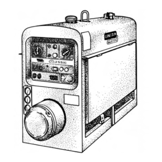
CLASSIC III/IIID
Gasoline & Diesel Engine Driven DC Arc Welding Power Source
For use with machine code numbers 10061, 10072 or 10156.
Safety Depends on You
Lincoln arc welding and cutting
equipment is designed and built
with safety in mind. However,
your overall safety can be in-
creased by proper installation . . .
and thoughtful operation on
your part. DO NOT INSTALL,
OPERATE OR REPAIR THIS
EQUIPMENT WITHOUT
READING THIS MANUAL AND
THE SAFETY PRECAUTIONS
CONTAINED THROUGHOUT.
And, most importantly, think
before you act and be careful.
SERVICE MANUAL
World's Leader in Welding and Cutting Products
Premier Manufacturer of Industrial Motors
Sales and Service through subsidiaries and Distributors Worldwide
22801 St. Clair Ave. Cleveland, Ohio 44117-1199 U.S.A. Tel. (216) 481-8100
Advertisement
Chapters
Table of Contents
Troubleshooting

Related Manuals for Lincoln Electric CLASSIC III SVM 137-A


Summary of Contents for Lincoln Electric CLASSIC III SVM 137-A
- Page 1 RETURN TO MAIN INDEX SVM 137-A January, 1998 CLASSIC III/IIID Gasoline & Diesel Engine Driven DC Arc Welding Power Source For use with machine code numbers 10061, 10072 or 10156. Safety Depends on You Lincoln arc welding and cutting equipment is designed and built with safety in mind.
-
Page 2: Safety
Miami, Florida 33135 or CSA Standard W117.2-1974. A Free copy of “Arc Welding Safety” booklet E205 is available from the Lincoln Electric Company, 22801 St. Clair Avenue, Cleveland, Ohio 44117-1199. BE SURE THAT ALL INSTALLATION, OPERATION, MAINTENANCE AND REPAIR PROCEDURES ARE PERFORMED ONLY BY QUALIFIED INDIVIDUALS. -
Page 3: Electric Shock Can Kill
ELECTRIC SHOCK can kill. 3.a. The electrode and work (or ground) circuits are electrically “hot” when the welder is on. Do not touch these “hot” parts with your bare skin or wet clothing. Wear dry, hole-free gloves to insulate hands. 3.b. - Page 4 WELDING SPARKS can cause fire or explosion. 6.a. Remove fire hazards from the welding area. If this is not possible, cover them to prevent the welding sparks from starting a fire. Remember that welding sparks and hot materials from welding can easily go through small cracks and openings to adjacent areas.
- Page 5 PRÉCAUTIONS DE SÛRETÉ Pour votre propre protection lire et observer toutes les instructions et les précautions de sûreté specifiques qui parraissent dans ce manuel aussi bien que les précautions de sûreté générales suiv- antes: Sûreté Pour Soudage A L’Arc 1. Protegez-vous contre la secousse électrique: a.
-
Page 6: Table Of Contents
MASTER TABLE OF CONTENTS FOR ALL SECTIONS Safety ...i-iv Installation...Section A Technical Specifications ...A-2 Safety Precautions ...A-3 Location and Ventilation ...A-3 Pre-operation Engine Service ...A-4 Electrical Output Connections...A-6 Operation...Section B Safety Instructions...B-2 General Description ...B-2 Recommended Applications...B-3 Operational Features and Controls...B-3 Design Features...B-3 Welding Capability ...B-4 Limitations ...B-4... - Page 7 Section A-1 - INSTALLATION SECTION - Installation Technical Specifications ...A-2 Safety Precautions ...A-3 Location and Ventilation ...A-3 Storing ...A-3 Stacking ...A-4 Tilting ...A-4 Lifting ...A-4 High Altitude Operation ...A-4 Pre-operation Engine Service ...A-4 Oil ...A-4 Fuel...A-4 Battery Connections ...A-4 Cooling System...A-5 Muffler ...A-5 Exhaust Spark Arrester ...A-5 Trailer ...A-5...
-
Page 8: Installation
TECHNICAL SPECIFICATIONS - CLASSIC III AND IIID Manufacturer Description Classic III: 4 cyl., 4 cycle Continental Water-cooled TM27 Gasoline 38.9 HP @ 1700 RPM Classic IIID: 4 cyl., 4 cycle Continental Water-cooled TMD27 Diesel 45 HP @ 1700 RPM Duty Cycle 100% Duty Cycle 50% Duty Cycle 30% Duty Cycle... -
Page 9: Safety Precautions
Read this entire installation section before you start installation. SAFETY PRECAUTIONS WARNING Do not attempt to use this equipment until you have thoroughly read all the operation and maintenance manuals supplied with your machine. They include important safety precautions; detailed engine starting, operating, and maintenance instructions;... -
Page 10: Stacking
STACKING Classic III and Classic IIID machines CANNOT be stacked. TILTING Place the machine on a secure, level surface whenev- er you use it or store it. Any surfaces you place it on other than the ground must be firm, non-skid, and structurally sound. -
Page 11: Cooling System
COOLING SYSTEM The cooling system has been filled at the factory with a 50-50 mixture of ethylene glycol antifreeze and water. Check the radiator level and add a 50-50 solution as needed. (See your engine manual or antifreeze con- tainer for alternate antifreeze recommendations.) MUFFLER This welder is supplied with an adjustable rain cap for the muffler. -
Page 12: Electrical Output Connections
Cable diameters are increased for long cable lengths to reduce voltage drops. Lincoln Electric offers a welding accessory kit with the properly specified Accessories section of this manual for more information. -
Page 13: Machine Grounding
MACHINE GROUNDING According to the United States National Electrical Code, the frame of this portable generator is not required to be grounded and is permitted to serve as the grounding means for cord connected equipment plugged into its receptacles. Some state, local or other codes or unusual operating circumstances may require the machine frame to be grounded. - Page 14 NOTES Classic III and IIID...
- Page 15 Section B-1 - OPERATION SECTION - Operation...Section B Safety Instructions...B-2 General Description ...B-2 Recommended Applications ...B-3 Welder ...B-3 Generator...B-3 Operational Features and Controls ...B-3 Design Features ...B-3 Welding Capability...B-4 Limitations ...B-4 Controls and Settings...B-5 Welder/Generator Controls ...B-5 Control of Welding Current ...B-6 Gasoline Engine Controls...B-7 Diesel Engine Controls ...B-8 Engine Operation ...B-9...
-
Page 16: Operation
OPERATING INSTRUCTIONS Read and understand this entire section before operat- ing your Classic III or Classic IIID. SAFETY INSTRUCTIONS WARNING Do not attempt to use this equipment until you have thoroughly read all the operation and maintenance manuals supplied with your machine. They include important safety precautions;... -
Page 17: Recommended Applications
RECOMMENDED APPLICATIONS WELDER The Classic III and Classic IIID provide excellent con- stant current DC welding output for stick (SMAW) weld- ing and for DC TIG welding. When equipped with the wire feed module, they also offer constant voltage out- put for DC semiautomatic wire feed welding. -
Page 18: Welding Capability
WELDING CAPABILITY The Classic III and Classic IIID are rated 300 amps, 32 volts constant current DC at 50% duty cycle based on a ten minute time period. Longer duty cycles at lower output currents are possible. The current is continuously variable from 40 to 350 amps DC. -
Page 19: Controls And Settings
CONTROLS AND SETTINGS The welder/generator controls are located on the Output Control Panel of the machine case front. Engine idler control and start/stop controls are also on WELDER/GENERATOR CONTROLS See Figure B.1 for the location of the following features: 1. CURRENT RANGE SELECTOR: Selects ranges of continuous current output for constant current stick or TIG applications and constant voltage wire feed applications (with optional Wire Feed Module). -
Page 20: Control Of Welding Current
CONTROL OF WELDING CURRENT CAUTION • DO NOT turn the CURRENT RANGE SELECTOR while welding because the current may arc between the contacts and damage the switch. • DO NOT attempt to set the CURRENT RANGE SELECTOR between the five points designated on the nameplate. -
Page 21: Gasoline Engine Controls
FIGURE B.3 – GASOLINE ENGINE CONTROLS 1. IDLER CONTROL TOGGLE SWITCH 2. IGNITION TOGGLE SWITCH 3. CHOKE 4. START PUSHBUTTON 5. ENGINE HOUR METER 6. AMMETER GASOLINE ENGINE CONTROLS (CLASSIC III) See Figure B.3 for the location of the following features: 1. -
Page 22: Diesel Engine Controls
FIGURE B.4 – DIESEL ENGINE CONTROLS 1. IDLER CONTROL TOGGLE SWITCH 2. IGNITION TOGGLE SWITCH 3. RESET BUTTON 4. START PUSHBUTTONS 5. ENGINE HOUR METER 6. OIL PRESSURE GAUGE 7. AMMETER 8. TEMPERATURE GAUGE DIESEL ENGINE CONTROLS (CLASSIC IIID) See Figure B.4 for the location of the following features: 1. -
Page 23: Engine Operation
ENGINE OPERATION WARNING DO NOT RUN THE ENGINE AT EXCESSIVE SPEEDS. The maximum allowable high idle speed for the Classic III and Classic IIID is 1800 RPM, no load. Do NOT increase the idle speed on the engine. Severe personal injury and damage to the machine can result if it is operated at speeds above the maximum rated speed. -
Page 24: Stopping The Engine
B-10 STOPPING THE ENGINE (GASOLINE OR DIESEL) 1. Place the IGNITION switch in the OFF position. At the end of each day’s welding, drain accumulated dirt and water from the sediment bowl under the fuel tank and from the fuel filter (diesel engine, Classic IIID) per instructions in the engine manufacturer’s operating manual. -
Page 25: Welding Operation
B-11 WELDING OPERATION TO USE THE CLASSIC III OR CLASSIC IIID FOR DC CONSTANT CURRENT STICK OR TIG WELDING: 1. Remove the flange nuts from the weld output ter- minals and place the work and electrode welding cables over the terminals. Replace and tighten the flange nuts securely. - Page 26 B-12 TO USE THE CLASSIC III OR CLASSIC IIID FOR DC WIRE FEED WELDING (CONSTANT VOLTAGE WITH WIRE FEED MODULE): 1. Connect the LN-25, LN-23P, or LN-7 Wire Feeder. Follow the installation instructions provided with the wire feeder. 2. Set the machine for CV operation. 3.
-
Page 27: Auxiliary Power
B-13 AUXILIARY POWER WARNING Be sure that any electrical equipment plugged into the generator AC power receptacles can withstand a ±10% voltage and a ±3% frequency variation. The AC auxiliary power, supplied as a standard, has a rating of 3.0 kVA of 115/230V AC power (60 hertz). One 115V duplex and one 230V duplex grounding type receptacle are provided. - Page 28 B-14 B-14 NOTES Classic III and IIID...
- Page 29 Options/Accessories ...C-2 TIG Welding Accessories...C-3 Semiautomatic FCAW and MIG Welding Accessories ...C-3 Connection of Lincoln Electric Wire Feeders...C-4 Connection of the LN-7 using K867 Universal Adapter ...C-4 Connection of the LN-7 using K584 Input Cable Assembly ...C-5 Connection of the LN-25 using K867 Universal Adapter ...C-6 Connection of the LN-25 “Across the Arc”...
-
Page 30: Accessories
OPTIONS/ACCESSORIES The following options/accessories are available for your Classic III or Classic IIID from your local Lincoln Distributor. Trailer (K913) - Two-wheeled trailer for in-plant and yard towing. Various hitches and accessories are available. For highway use, consult applicable federal, state, and local laws. -
Page 31: Tig Welding Accessories
TIG WELDING ACCESSORIES K930-2 TIG Module - The TIG Module is an accessory that provides high frequency & shielding gas control for DC GTAW (TIG) welding applications. The TIG Module is supplied without accessories. Arc start switches, amptrols, cables, torches and mounting brackets must be purchased separately. -
Page 32: Connection Of Lincoln Electric Wire Feeders
CONNECTION OF LINCOLN ELECTRIC WIRE FEEDERS CONNECTION OF THE LN-7 TO THE CLASSIC III OR CLASSIC IIID (EQUIPPED WITH K623-1 WIRE FEED MODULE) USING K867 UNIVERSAL ADAPTER (SEE FIGURE C.1.) 1. Shut the welder off. 2. Connect the electrode cable from the LN-7 to the “+”... - Page 33 CONNECTION OF THE LN-7 TO THE CLASSIC III OR CLASSIC IIID (EQUIPPED WITH K623-1 WIRE FEED MODULE) USING K584 INPUT CABLE ASSEMBLY (SEE FIGURE C.2.) 1. Shut the welder off. 2. Connect the electrode cable from the LN-7 to the “+”...
- Page 34 CONNECTION OF THE LN-25 TO THE CLASSIC III OR CLASSIC IIID (EQUIPPED WITH K623-1 WIRE FEED MODULE) USING K867 UNIVERSAL ADAPTER (SEE FIGURE C.3.) 1. Shut the welder off. 2. Connect the electrode cable from the LN-25 to the “+” terminal of the welder. Connect the work cable to the “CV-”...
- Page 35 CONNECTION OF THE LN-25 TO THE CLASSIC III OR CLASSIC IIID (EQUIPPED WITH K623-1 WIRE FEED MODULE) “ACROSS THE ARC” (SEE FIGURE C.4.) 1. Shut the welder off. 2. Connect the electrode cable from the LN-25 to the “+” terminal of the welder. Connect the work cable to the “CV–”...
-
Page 36: Installation
CONNECTION OF THE LN-23P TO THE CLASSIC III OR CLASSIC IIID (EQUIPPED WITH K623-1 WIRE FEED MODULE) USING THE K-350-1 ADAPTER KIT (SEE FIGURE C.5) 1. Shut the welder off. 2. Connect the electrode cable from the LN-23P to the “CV”... -
Page 37: Connection Of The K488 Sg Control Module And K487 Magnum Spool Gun
CONNECTION OF THE K488 SG CONTROL MODULE AND K487 MAGNUM SPOOL GUN TO THE CLASSIC III OR CLASSIC IIID (EQUIPPED WITH K623-1 WIRE FEED MODULE) (SEE FIGURE C.6.) 1. Shut the welder off. 2. Connect the electrode cable from the SG Control Module to the “+”... - Page 38 C-10 C-10 NOTES Classic III and IIID...
-
Page 39: Routine And Periodic Maintenance
Section D-1 Maintenance ...Section D Safety Precautions ...D-2 Routine and Periodic Maintenance ...D-2 Engine Maintenance...D-2 Change the Oil ...D-2 Change the Oil Filter ...D-3 Fuel...D-3 Fuel Filter...D-4 Air Cleaner...D-4 How to Eliminate Air From the Fuel System ...D-5 Cooling System ...D-6 Spark Plugs ...D-6 Tightening the Fan Belt ...D-7 Engine Maintenance Schedule...D-8... -
Page 40: Safety Precautions
SAFETY PRECAUTIONS WARNING • Have qualified personnel do all maintenance and troubleshooting work. • Turn the engine off before working inside the machine. • Remove covers or guards only when necessary to perform maintenance and replace them when the maintenance requiring their removal is complete. •... -
Page 41: Change The Oil Filter
CHANGE THE OIL FILTER: Change the oil filter the first time between 25 and 50 hours of operation. Then, under normal operating conditions, change the oil filter per Table D.1 or consult your engine Owner’s Manual. If the engine is operated under heavy load or in high ambient temperatures, change the oil filter more fre- quently. - Page 42 FUEL FILTER - DIESEL ENGINE (CLASSIC IIID CODES ABOVE 10061 WITH STANADYNE FUEL FILTER): The diesel engine fuel filter is a metal canister ele- ment type. It cannot be cleaned. Replace the filter per Table D.1 or if there is reason to believe it is plugged.
-
Page 43: How To Eliminate Air From The Fuel System
HOW TO ELIMINATE AIR FROM THE FUEL SYSTEM – DIESEL ENGINE (CLASSIC IIID) The following procedure is for Classic IIID diesel engines with a Stanadyne type fuel filter (Figure D.2). If your filter is different, refer to your engine Owner’s Manual for the correct procedure for eliminating air from the system. - Page 44 FIGURE D.4 – ENGINE COOLANT DRAIN PLUG AND RADIATOR DRAIN COCK COOLING SYSTEM: The Continental engine, gaso- line or diesel, is water cooled. Check the coolant level at the radiator filler daily. Add a 50-50 mixture of water and antifreeze as needed. To drain and refill the sys- tem, do the following: 1.
-
Page 45: Tightening The Fan Belt
TIGHTENING THE FAN BELT: Fan belts tend to loosen after the first 50 hours of operation. If the fan belts are loose, the engine can overheat and the bat- tery can lose its charge. Check belt tightness by press- ing on the belt midway between the pulleys. The belt should deflect no more than 13 mm (0.5 in.). -
Page 46: Cooling System
HOURS BETWEEN SERVICING DAILY C or R I = Inspect C = Clean R = Replace NOTES: (1) Consult engine Owner’s Manual for all recommendations. (2) Or Equivalent. (3) First inspection after 50 hours; every 500 thereafter. (4) Gasoline engine only. (5) Diesel engine only. -
Page 47: Battery Maintenance
BATTERY MAINTENANCE WARNING GASES FROM BATTERY can explode. • Keep sparks, flame, and cigarettes away from battery. BATTERY ACID can burn eyes and skin. • Wear gloves and eye protection and be careful when working near a battery. Follow the instructions printed on the battery. -
Page 48: Welder/Generator Maintenance
D-10 WELDER/GENERATOR MAINTENANCE STORAGE: Store the Classic III or Classic IIID in clean, dry, protected areas. CLEANING: Blow out the generator and controls peri- odically with low pressure air. Do this at least once a week in particularly dirty areas. NAMEPLATES: Whenever routine maintenance is performed on this machine - or at least yearly - inspect... -
Page 49: Idler Maintenance
D-11 IDLER MAINTENANCE 1. The solenoid plunger must work freely because binding can cause engine surging. occurs, be sure the plunger is properly lined up with the throttle lever. Dust the plunger about once a year with graphite powder. 2. When any service is done, reassemble the rubber bellows on the solenoid plunger with the vent hole on the lower side. -
Page 50: Major Component Locations
D-12 FIGURE D.7 - MAJOR COMPONENT LOCATIONS 1. RIGHT CASE SIDE (DOOR) 2. BASE (WITH BATTERY) 3. ALTERNATOR BRUSHES 4. ALTERNATOR 5. GENERATOR 6. GENERATOR BRUSHES 7. OUTPUT TERMINALS 8. FUEL TANK 9. CASE FRONT WITH CONTROL PANEL 10. LEFT CASE SIDE 11. - Page 51 D-13 D-13 NOTES Classic III and IIID...
- Page 52 D-14 D-14 NOTES Classic III and IIID...
-
Page 53: Theory Of Operation Section
Section E-1 -THEORY OF OPERATION SECTION- Theory of Operation ...Section E General Description ...E-2 Battery, Starter, Engine Alternator and Oil Switch Circuits (Classic III) ...E-3 Battery, Starter, Engine Alternator and Engine Protection Circuitry (Classic IIID) ...E-4 Engine, Generator Armature and Frame, Alternator Stator and Rotor...E-5 Excitation (Flashing)...E-5 Auxiliary and Field Feedback Coils ...E-5 Interpole and Series Coils...E-5... -
Page 54: Theory Of Operation
THEORY OF OPERATION GENERAL DESCRIPTION The Classic III and Classic IIID are heavy duty, engine driven, DC arc welding power sources capable of pro- viding constant current output for stick welding or DC TIG welding. Also, a total of 3000 watts of auxiliary FIGURE E.1a –... -
Page 55: Battery, Starter, Engine Alternator And Oil Switch Circuits (Classic Iii
THEORY OF OPERATION FIGURE E.2a – BATTERY, STARTER, ENGINE ALTERNATOR AND OIL SWITCH CIRCUIT (CLASSIC III) BATTERY, STARTER, ENGINE ALTERNATOR AND OIL SWITCH CIRCUIT (CLASSIC III) The 12VDC battery powers the starter motor and, through the ignition switch, the engine ignition and fuel shutoff solenoid. -
Page 56: Battery, Starter, Engine Alternator And Engine Protection Circuitry (Classic Iiid
THEORY OF OPERATION FIGURE E.2b – BATTERY, STARTER, ENGINE ALTERNATOR AND ENGINE PROTECTION CIRCUITRY (CLASSIC IIID) BATTERY, STARTER, ENGINE ALTERNATOR AND PROTECTION CIRCUITRY (CLASSIC IIID) The 12VDC battery powers the starter motor, glow plugs and the engine protection circuitry. The fuel pump and solenoid are powered from the protection cir- cuit through the ignition switch. -
Page 57: Engine, Generator Armature And Frame, Alternator Stator And Rotor
THEORY OF OPERATION FIGURE E.3 – ENGINE, GENERATOR ARMATURE AND FRAME, ALTERNATOR STATOR AND ROTOR (CLASSIC III) NOTE: Unshaded areas of Block Logic Diagram are the subject of discussion. ENGINE, GENERATOR ARMATURE AND FRAME, ALTERNATOR STATOR AND ROTOR EXCITATION (FLASHING) When the engine is started and running, the residual magnetism voltage is applied to the alternator rotor through a brush and slip ring configuration. -
Page 58: Current Range Selector
THEORY OF OPERATION CURRENT RANGE SELECTOR The selector switch acts as a coarse current adjustment by allowing varying amounts of series windings to be included in the welding current path. The series coils and selector switch are connected in series with the negative output terminal. -
Page 59: Mechanical Coupling
THEORY OF OPERATION FIGURE E.4 – DC GENERATOR MACHINES MECHANICAL COUPLING DC GENERATOR MACHINES The armature winding of a DC generator is located on the rotating member. Current is conducted from it by means of carbon brushes. The field winding is located in the stator, which is stationary, and is excited by direct current. - Page 60 NOTES Classic III and IIID...
-
Page 61: Troubleshooting & Repair Section
Section F-1 TROUBLESHOOTING & REPAIR SECTION Troubleshooting & Repair Section...Section F How to Use Troubleshooting Guide ...F-2 PC Board Troubleshooting Procedures...F-3 Troubleshooting Guide ...F-4 - F-13 Test Procedures ...F-14 Alternator Rotor Test...F-14 Field Shunt Winding Test ...F-18 Flashing the Fields ...F-21 Idler Solenoid Test ...F-23 Engine Throttle Adjustment Test - Classic IIID (Diesel)...F-25 Engine Throttle Adjustment Test - Classic III (Gasoline) ...F-29... -
Page 62: How To Use Troubleshooting Guide
TROUBLESHOOTING & REPAIR HOW TO USE TROUBLESHOOTING GUIDE Service and repair should be performed by only Lincoln Electric Factory Trained Personnel. Unauthorized repairs performed on this equipment may result in danger to the technician and machine operator and will invalidate your factory warranty. For your safety and to avoid Electrical Shock, please observe all safety notes and precautions detailed throughout this manual. -
Page 63: Pc Board Troubleshooting Procedures
• If the PC Board uses protective shorting jumpers, don’t remove them until installation is complete. • If you return a PC Board to The Lincoln Electric Company for credit, it must be in the static-shielding bag. This will prevent further damage and allow prop- er failure analysis. -
Page 64: Troubleshooting Guide
AC auxiliary output voltage. If for any reason you do not understand the test procedures or are unable to perform the test/repairs safely, con- tact the Lincoln Electric Service Department for electrical troubleshooting assistance before you proceed. Call 216-383-2531 or 1-800-833-9353. - Page 65 If for any reason you do not understand the test procedures or are unable to perform the test/repairs safely, con- tact the Lincoln Electric Service Department for electrical troubleshooting assistance before you proceed. Call 216- 383-2531 or 1-800-833-9353.
- Page 66 If for any reason you do not understand the test procedures or are unable to perform the test/repairs safely, con- tact the Lincoln Electric Service Department for electrical troubleshooting assistance before you proceed. Call 216-383-2531 or 1-800-833-9353. POSSIBLE AREAS OF...
- Page 67 Control rheostat is adjusted. If for any reason you do not understand the test procedures or are unable to perform the test/repairs safely, con- tact the Lincoln Electric Service Department for electrical troubleshooting assistance before you proceed. Call 216- 383-2531 or 1-800-833-9353.
- Page 68 If for any reason you do not understand the test procedures or are unable to perform the test/repairs safely, con- tact the Lincoln Electric Service Department for electrical troubleshooting assistance before you proceed. Call 216-383-2531 or 1-800-833-9353.
- Page 69 If for any reason you do not understand the test procedures or are unable to perform the test/repairs safely, con- tact the Lincoln Electric Service Department for electrical troubleshooting assistance before you proceed. Call 216-383-2531 or 1-800-833-9353. detailed in the beginning of this manual.
- Page 70 The engine will not shut down. If for any reason you do not understand the test procedures or are unable to perform the test/repairs safely, con- tact the Lincoln Electric Service Department for electrical troubleshooting assistance before you proceed. Call 216-383-2531 or 1-800-833-9353.
- Page 71 If for any reason you do not understand the test procedures or are unable to perform the test/repairs safely, con- tact the Lincoln Electric Service Department for electrical troubleshooting assistance before you proceed. Call 216-383-2531 or 1-800-833-9353. detailed in the beginning of this manual.
- Page 72 If for any reason you do not understand the test procedures or are unable to perform the test/repairs safely, con- tact the Lincoln Electric Service Department for electrical troubleshooting assistance before you proceed. Call 216-383-2531 or 1-800-833-9353.
- Page 73 If for any reason you do not understand the test procedures or are unable to perform the test/repairs safely, con- tact the Lincoln Electric Service Department for electrical troubleshooting assistance before you proceed. Call 216-383-2531 or 1-800-833-9353. detailed in the beginning of this manual.
-
Page 74: Test Description
TROUBLESHOOTING & REPAIR ALTERNATOR ROTOR TEST Service and repair should be performed by only Lincoln Electric factory trained personnel. Unauthorized repairs performed on this equipment may result in danger to the technician or machine operator and will invalidate your factory warranty. For your safety and to avoid electrical shock, please observe all safety notes and precautions detailed throughout this manual. -
Page 75: Troubleshooting And Repair
F-15 TROUBLESHOOTING & REPAIR ALTERNATOR ROTOR TEST (continued) ALTERNATOR COVER TEST PROCEDURE 1. Turn engine off. 2. With the 3/8" nut driver or socket wrench, loosen the screws on the left and right sides and bottom of the alternator wrap- around. - Page 76 F-16 TROUBLESHOOTING & REPAIR ALTERNATOR ROTOR TEST (continued) 6. Working from the left side of the machine, measure the resistance across the rotor slip rings. a. Set the ohmmeter on the low scale (X1). b. Place one meter probe on one of the rotor slip rings.
- Page 77 F-17 TROUBLESHOOTING & REPAIR ALTERNATOR ROTOR TEST (continued) 7. Measure the rotor resistance to ground. a. Set the ohmmeter on the high scale (X100,000). b. Place one probe on either of the rotor slip rings. Place the other probe on any good, unpainted ground.
-
Page 78: Field Shunt Winding Test
TROUBLESHOOTING & REPAIR FIELD SHUNT WINDING TEST Service and repair should be performed by only Lincoln Electric factory trained personnel. Unauthorized repairs performed on this equipment may result in danger to the technician or machine operator and will invalidate your factory warranty. For your safety and to avoid elec- trical shock, please observe all safety notes and precautions detailed throughout this manual. - Page 79 F-19 TROUBLESHOOTING & REPAIR FIELD SHUNT WINDING TEST (continued) TEST PROCEDURE 1. Turn engine off. 2. Unlatch, lift and secure the left side door. Note that there are latches at both ends of the door. 3. Locate and remove plug P10. See Figure F.4.
- Page 80 F-20 TROUBLESHOOTING & REPAIR FIELD SHUNT WINDING TEST (continued) FIGURE F.5 – SHUNT LEAD RESISTANCE CHECK PIN 5 5. Using the volt/ohmmeter set on the low scale (X1), measure the resistance between the blue and the brown leads. See Figure F.5. approximately 50 ohms.
-
Page 81: Flashing The Fields
F-21 TROUBLESHOOTING & REPAIR Service and repair should be performed by only Lincoln Electric factory trained personnel. Unauthorized repairs performed on this equipment may result in danger to the technician or machine operator and will invalidate your factory warranty. For your safety and to avoid elec- trical shock, please observe all safety notes and precautions detailed throughout this manual. - Page 82 F-22 TROUBLESHOOTING & REPAIR FLASHING THE FIELDS (continued) PROCEDURE 1. Turn engine OFF. 2. Remove the cover from the exiter. Figure F.6. 3. Turn the FINE CURRENT ADJUSTMENT control (rheostat) to “100.” 4. Using one of the leads with alligator clips, connect the negative terminal of the 12-volt automotive battery to the negative brush- holder.
-
Page 83: Idler Solenoid Test
F-23 TROUBLESHOOTING & REPAIR Service and repair should be performed by only Lincoln Electric factory trained personnel. Unauthorized repairs performed on this equipment may result in danger to the technician or machine operator and will invalidate your factory warranty. For your safety and to avoid elec- trical shock, please observe all safety notes and precautions detailed throughout this manual. - Page 84 F-24 TROUBLESHOOTING & REPAIR IDLER SOLENOID TEST (continued) FIGURE F.7 - SOLENOID LEAD CONNECTIONS LEADS 56 & 57 SOLENOID TEST PROCEDURE 1. Turn engine off. 2. Unlatch, lift and secure the left side door. Note that there are latches at both ends of the door.
-
Page 85: Engine Throttle Adjustment Test - Classic Iiid (Diesel
TROUBLESHOOTING & REPAIR ENGINE THROTTLE ADJUSTMENT TEST - CLASSIC IIID Service and repair should be performed by only Lincoln Electric factory trained personnel. Unauthorized repairs performed on this equipment may result in danger to the technician or machine operator and will invalidate your factory warranty. For your safety and to avoid elec- trical shock, please observe all safety notes and precautions detailed throughout this manual. - Page 86 F-26 TROUBLESHOOTING & REPAIR ENGINE THROTTLE ADJUSTMENT TEST (continued) FIGURE F.8 - STROBE MARK LOCATION STROBE TEST PROCEDURE Strobe Tach Method 1. Turn the engine welder OFF. 2. Unlatch, lift and secure the left side door. Note that there are latches at both ends of the door.
- Page 87 F-27 TROUBLESHOOTING & REPAIR ENGINE THROTTLE ADJUSTMENT TEST (continued) 6. If either of the readings is incorrect, adjust the throttle as follows: Adjust HIGH IDLE: Use the 5/16” wrench to loosen the locking nut. See Figure F.9 for location of the adjusting screw and locking nut.
-
Page 88: Adjusting Screw
F-28 F-28 TROUBLESHOOTING & REPAIR ENGINE THROTTLE ADJUSTMENT TEST (continued) FIGURE F.9 - HIGH IDLE ADJUSTMENT ADJUSTING SCREW LOCKING NUT FIGURE F.10 - LOW IDLE ADJUSTMENT SOLENOID LOCKING NUT THREADED LEVER ARM Classic III and IIID... - Page 89 TROUBLESHOOTING & REPAIR ENGINE THROTTLE ADJUSTMENT TEST - CLASSIC III Service and repair should be performed by only Lincoln Electric factory trained personnel. Unauthorized repairs performed on this equipment may result in danger to the technician or machine operator and will invalidate your factory warranty. For your safety and to avoid elec- trical shock, please observe all safety notes and precautions detailed throughout this manual.
- Page 90 F-30 TROUBLESHOOTING & REPAIR ENGINE THROTTLE ADJUSTMENT TEST (continued) FIGURE F.11 - BLOWER PADDLE MARK LOCATION TEST PROCEDURE STROBE TACH METHOD 1. Conduct this procedure with the engine OFF. 2. Unlatch, lift, and secure the right and left side doors. 3.
-
Page 91: Frequency Counter Method
F-31 TROUBLESHOOTING & REPAIR 6. If either of these readings is incorrect, adjust the throttle as follows: Adjust High Idle a. Make sure there is no load on the machine. b. Set the Idler switch to the HIGH position. c. Locate the governor on the left side of the engine. See Figure F.12. - Page 92 F-32 TROUBLESHOOTING & REPAIR OSCILLOSCOPE METHOD 1. Connect the oscilloscope to the 115 VAC recepta- cle, according to the manufacturer's instructions. At HIGH IDLE (1800 RPM), the waveform should exhibit a period of 16.6 milliseconds. At LOW IDLE (1400 RPM), the waveform should exhibit a period of 21.4 milliseconds.
-
Page 93: Installation
F-33 ENGINE THROTTLE ADJUSTMENT TEST (continued) FIGURE F.13 - LOW IDLE ADJUSTMENT IDLER LOCKING INSTALLATION SPEED ADJUSTMENT SCREW Classic III and IIID F-33... -
Page 94: Normal Open Circuit Voltage Waveform (115Vac Supply
F-34 TROUBLESHOOTING & REPAIR NORMAL OPEN CIRCUIT VOLTAGE WAVEFORM (115VAC SUPPLY) HIGH IDLE – NO LOAD – FINE CURRENT CONTROL RHEOSTAT AT MAXIMUM 16.6 ms 5 ms 50 volts This is the typical auxiliary output voltage generated from a properly operating machine. -
Page 95: Troubleshooting And Repair
F-35 TROUBLESHOOTING & REPAIR NORMAL OPEN CIRCUIT DC WELD VOLTAGE WAVEFORM HIGH IDLE – NO LOAD – FINE CURRENT CONTROL RHEOSTAT AND SELECTOR SWITCH AT MAXIMUM 5 ms 50 volts This is the typical DC output voltage generated from a properly operating machine. -
Page 96: Typical Dc Weld Output Voltage Waveform
F-36 TROUBLESHOOTING & REPAIR TYPICAL DC WELD OUTPUT VOLTAGE WAVEFORM MACHINE LOADED – SELECTOR SWITCH AT MAXIMUM POSITION MACHINE LOADED TO 250 AMPS AT 40 VDC 5 ms 20 volts This is the typical DC output voltage generated from a properly operating machine. -
Page 97: Alternator Rotor Removal And Replacement
TROUBLESHOOTING & REPAIR ALTERNATOR ROTOR REMOVAL Service and repair should be performed by only Lincoln Electric factory trained personnel. Unauthorized repairs performed on this equipment may result in danger to the technician or machine operator and will invalidate your factory warranty. For your safety and to avoid elec- trical shock, please observe all safety notes and precautions detailed throughout this manual. - Page 98 F-38 TROUBLESHOOTING & REPAIR ALTERNATOR ROTOR REMOVAL AND REPLACEMENT (continued) PROCEDURE 1. Turn the engine off. 2. Using the 7/16” wrench, remove the two bolts and washers and partially slide out the battery mounting panel. See Figure F.14 3. With the 1/2" wrench, disconnect the negative battery cable.
-
Page 99: Slip Rings
F-39 TROUBLESHOOTING & REPAIR ALTERNATOR ROTOR REMOVAL AND REPLACEMENT (continued) See Figure F.15 for steps 3 - 5. 3. With the 3/8" wrench, loosen the screws on the left and right sides and bottom of the alter- nator wrap-around. 4. With the 5/16" wrench, remove the 4 screws from the alternator cover. -
Page 100: Brush Holder Assembly
F-40 TROUBLESHOOTING & REPAIR ALTERNATOR ROTOR REMOVAL AND REPLACEMENT (continued) See Figure F.16 for steps 6 - 8. 6. With the 7/16" wrench, remove the two bolts, nuts and washers mounting the brush holder assembly to the stator frame. 7. Bend the flat washer away from the rotor lock- ing nut. - Page 101 F-41 ALTERNATOR ROTOR REMOVAL AND REPLACEMENT (continued) Replacement 9. Carefully mount the rotor onto the generator shaft. Install a new sleeve collar (part num- ber T14337), washer, and rotor locking nut. NOTE: Be careful not to damage or deform the new sleeve collar. Carefully tap the new sleeve collar into position.
-
Page 102: Alternator Stator Removal And Replacement
TROUBLESHOOTING & REPAIR ALTERNATOR STATOR REMOVAL AND REPLACEMENT Service and repair should be performed by only Lincoln Electric factory trained personnel. Unauthorized repairs performed on this equipment may result in danger to the technician or machine operator and will invalidate your factory warranty. For your safety and to avoid elec- trical shock, please observe all safety notes and precautions detailed throughout this manual. - Page 103 F-43 TROUBLESHOOTING & REPAIR ALTERNATOR STATOR REMOVAL AND REPLACEMENT (continued) FIGURE F.17 – COMMUTATOR WRAP-AROUND REMOVAL PROCEDURE 1. Turn the engine OFF. 2. Perform the Alternator Rotor Removal procedure. 3. With the 1/2" wrench, remove the four nuts and bolts holding the case top and doors assembly to the welder frame.
- Page 104 F-44 TROUBLESHOOTING & REPAIR ALTERNATOR STATOR REMOVAL AND REPLACEMENT (continued) FIGURE F.18 - LEAD DISCONNECTION POINTS FIGURE F.19- LEAD DISCONNECTION – CIRCUIT BREAKER, RECEPTACLES, FIELD BRIDGE RECTIFIER YELLOW AND WHITE WIRE IN-LINE CONNECTORS; YELLOW LEADS; BLACK CURRENT TRANSFORMER LEAD ALL LOCATED BEHIND CASE FRONT 230 VAC RECEPTACLE CB1 CIRCUIT BREAKER...
- Page 105 F-45 TROUBLESHOOTING & REPAIR ALTERNATOR STATOR REMOVAL AND REPLACEMENT (continued) 13. Clear the leads in preparation for remov- ing the stator/end bracket. FIGURE F.20 - GENERATOR BRUSH HOLDER CABLE REMOVAL GENERNATOR BRUSH HOLDER/COIL CABLES (4) 15. With the 1/2" wrench, disconnect and clear the four heavy cables from the gen- erator brush holders to the coils in the generator frame.
- Page 106 F-46 TROUBLESHOOTING & REPAIR ALTERNATOR STATOR REMOVAL AND REPLACEMENT (continued) FIGURE F.21 - DRILL SPOT LOCATIONS BRUSH HOLDER DRILL SPOT LOCATION STATOR/END BRACKET 16. With the 5/8" wrench, remove the four bolts mounting the stator/end bracket assembly to the generator frame. Note the "drill spot"...
-
Page 107: Generator Frame Removal And Replacement
TROUBLESHOOTING & REPAIR REMOVAL AND REPLACEMENT Service and repair should be performed by only Lincoln Electric factory trained personnel. Unauthorized repairs performed on this equipment may result in danger to the technician or machine operator and will invalidate your factory warranty. For your safety and to avoid elec- trical shock, please observe all safety notes and precautions detailed throughout this manual. - Page 108 F-48 TROUBLESHOOTING & REPAIR GENERATOR FRAME REMOVAL AND REPLACEMENT (continued) FIGURE F.22 – FUEL TANK / OUTPUT CABLE REMOVAL POSITIVE CABLE COPPER STRAP PROCEDURE 1. Turn the engine OFF. 2. Perform the Alternator Rotor Removal procedure. 3. Perform the Alternator Stator Removal procedure.
- Page 109 F-49 TROUBLESHOOTING & REPAIR GENERATOR FRAME REMOVAL AND REPLACEMENT (continued) FIGURE F.23 – WIRE AND SELECTOR SWITCH CONNECTIONS FINE CURRENT ADJUSTMENT RHEOSTAT FIELD BRIDGE See Figure F.23 for steps 10 - 13. 10. Cut all necessary cable ties. 11. Disconnect the blue and the brown wires at the in- line connectors.
- Page 110 F-50 TROUBLESHOOTING & REPAIR GENERATOR FRAME REMOVAL AND REPLACEMENT (continued) FIGURE F.24 – CASE FRONT REMOVAL STEP #16 See Figure F.24 for steps 14 - 16. 14. With the 9/16" wrench, remove the four bolts and lock washers holding the case front to the welder frame.
- Page 111 F-51 TROUBLESHOOTING & REPAIR GENERATOR FRAME REMOVAL AND REPLACEMENT (continued) FIGURE F.25 – FRAME MOUNTING DETAILS See Figure F.25 for steps 17 - 20. 17. With the 3/4" wrench, remove the frame mounting bolts, nuts and spacers from the feet of the generator frame. 18.
- Page 112 F-52 TROUBLESHOOTING & REPAIR GENERATOR FRAME REMOVAL AND REPLACEMENT (continued) 27. Re-attach the positive output terminal cable. 28. Set the fuel tank into position on the rails and secure it with the four bolts, washers, and nuts. 29. Attach the fuel return line at the top of the fuel tank (Diesel engine only).
-
Page 113: Generator Armature Removal And Replacement
TROUBLESHOOTING & REPAIR REMOVAL AND REPLACEMENT Service and repair should be performed by only Lincoln Electric factory trained personnel. Unauthorized repairs performed on this equipment may result in danger to the technician or machine operator and will invalidate your factory warranty. For your safety and to avoid elec- trical shock, please observe all safety notes and precautions detailed throughout this manual. - Page 114 F-54 TROUBLESHOOTING & REPAIR GENERATOR ARMATURE REMOVAL AND REPLACEMENT (continued) FIGURE F.26 – BLOWER PADDLE REMOVAL PROCEDURE 1. Turn the engine OFF. 2. Perform the Alternator Rotor Removal pro- cedure. 3. Perform the Alternator Stator Removal pro- cedure. 4. Perform the Generator Frame Removal pro- cedure.
-
Page 115: Retest After Repair
F-55 TROUBLESHOOTING & REPAIR Retest a machine: • If it is rejected under test for any reason that requires you to remove any mechanical part which could affect the machine’s electrical characteristics. • If you repair or replace any electrical components. Mode Low Idle High Idle... - Page 116 F-56 F-56 NOTES Classic III and IIID...
- Page 117 ELECTRICAL DIAGRAMS TABLE OF CONTENTS ELECTRICAL DIAGRAMS SECTION Electrical Diagrams Section...Section G Wiring Diagram ...G-3 Wiring Diagram ...G-5 Wiring Diagram Wire Feed Module...G-7 Idler PC Board Schmatic ...G-9 Idler PC Board Layout ...G-11 CLASSIC III/IIID...
- Page 118 Notes CLASSIC III/IIID...
-
Page 119: Electrical Diagrams
ELECTRICAL DIAGRAMS Wiring Diagram- Classic IIID NOTE: This diagram is for reference only. It may not be accurate for all machines covered by this manual. The wiring diagram specific to your code is pasted inside one of the enclosure panels of your machine. CLASSIC III/IIID... - Page 120 Notes CLASSIC III/IIID...
- Page 121 Individual Printed Circuit Board Components are not available from Lincoln Electric. This information is provided for reference only. Lincoln Electric discourages board level troubleshooting and repair since it may compromise the quality of the design and may result in danger to the Machine Operator or Technician. Improper PC board repairs could result in damage to the machine.
- Page 122 Notes CLASSIC III/IIID...
- Page 123 ELECTRICAL DIAGRAMS Wiring Diagram - Wire Feed Module R502 NOTE: This diagram is for reference only. It may not be accurate for all machines covered by this manual. The wiring diagram specific to your code is pasted inside one of the enclosure panels of your machine. CLASSIC III/IIID...
- Page 124 Notes CLASSIC III/IIID...
- Page 125 Individual Printed Circuit Board Components are not available from Lincoln Electric. This information is provided for reference only. Lincoln Electric discourages board level troubleshooting and repair since it may compromise the quality of the design and may result in danger to the Machine Operator or Technician. Improper PC board repairs could result in damage to the machine.
- Page 126 G-10 G-10 Notes CLASSIC III/IIID...
- Page 127 Individual Printed Circuit Board Components are not available from Lincoln Electric. This information is provided for reference only. Lincoln Electric discourages board level troubleshooting and repair since it may compromise the quality of the design and may result in danger to the Machine Operator or Technician. Improper PC board repairs could result in damage to the machine.
- Page 128 G-12 G-12 Notes CLASSIC III/IIID...
Need help?
Do you have a question about the CLASSIC III SVM 137-A and is the answer not in the manual?
Questions and answers