Table of Contents
Advertisement
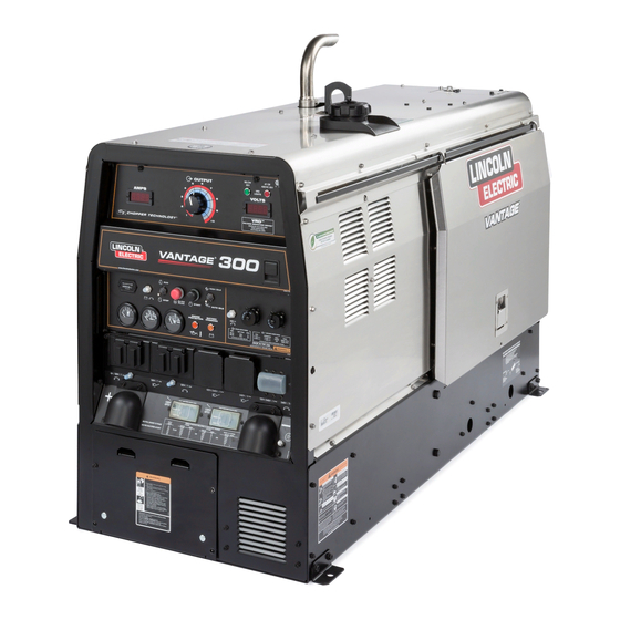
For use with machines having Code Numbers:
Safety Depends on You
Lincoln arc welding and cutting
equipment is designed and built
with safety in mind. However,
your overall safety can be
increased by proper installation
... and thoughtful operation on
your part. DO NOT INSTALL,
OPERATE OR REPAIR THIS
EQUIPMENT WITHOUT READ-
ING THIS MANUAL AND THE
SAFETY PRECAUTIONS CON-
TAINED THROUGHOUT. And,
most importantly, think before
you act and be careful.
• Sales and Service through Subsidiaries and Distributors Worldwide •
Cleveland, Ohio 44117-1199 U.S.A. TEL: 216.481.8100 FAX: 216.486.1751 WEB SITE: www.lincolnelectric.com
RETURN TO MAIN MENU
®
VANTAGE
11528
OPERATOR'S MANUAL
• World's Leader in Welding and Cutting Products •
3
Copyright © Lincoln Global Inc.
IM992
November, 2010
Advertisement
Table of Contents

Related Manuals for Lincoln Electric VANTAGE 300 IM992


Summary of Contents for Lincoln Electric VANTAGE 300 IM992
- Page 1 VANTAGE For use with machines having Code Numbers: Safety Depends on You Lincoln arc welding and cutting equipment is designed and built with safety in mind. However, your overall safety can be increased by proper installation ... and thoughtful operation on your part.
-
Page 2: California Proposition 65 Warnings
351040, Miami, Florida 33135 or CSA Standard W117.2-1974. A Free copy of “Arc Welding Safety” booklet E205 is available from the Lincoln Electric Company, 22801 St. Clair Avenue, Cleveland, Ohio 44117-1199. bE SURE THAT ALL INSTALLATION, OPERATION, MAINTENANCE AND REPAIR PROCEDURES ARE PERFORMED ONLY bY QUALIFIED INDIVIDUALS. -
Page 3: Electric Shock Can Kill
ELECTRIC SHOCK can kill. 3.a. The electrode and work (or ground) circuits are electrically “hot” when the welder is on. Do not touch these “hot” parts with your bare skin or wet clothing. Wear dry, hole-free gloves to insulate hands. - Page 4 WELDING and CUTTING SPARKS can cause fire or explosion. 6.a. Remove fire hazards from the welding area. If this is not possible, cover them to prevent the welding sparks from starting a fire. Remember that welding materials from welding can easily go through small cracks and openings to adjacent areas.
- Page 5 PRÉCAUTIONS DE SÛRETÉ Pour votre propre protection lire et observer toutes les instruc- tions et les précautions de sûreté specifiques qui parraissent dans ce manuel aussi bien que les précautions de sûreté générales suivantes: Sûreté Pour Soudage A L’Arc 1. Protegez-vous contre la secousse électrique: a.
- Page 6 Electric for advice or information about their use of our products. We respond to our customers based on the best information in our posses- sion at that time. Lincoln Electric is not in a position to warrant or guarantee such advice, and assumes no liability, with respect to such infor- mation or advice.
-
Page 7: Table Of Contents
Welding Terminals ...A-6 Welding Output Cables ...A-7 Cable Installation...A-7 Auxiliary Power Receptacles and Plugs ...A-7 Standby Power Connections ...A-8 Premises Wiring ...A-9 Connection of Lincoln Electric Wire Feeders...A-10, A-11 ________________________________________________________________________________ Operation...Section b Safety Precautions ...B-1 General Description...B-1 For Auxiliary Power ...B-1 Engine Operation...B-1... - Page 8 Fuel ...D-4 Bleeding the Fuel System ...D-4 Fuel Filter ...D-5 Engine Adjustment ...D-5 Battery Maintenance ...D-5 Servicing Optional Spark Arrestor ...D-5 Welder / Generator Maintenance ...D-6 Storage ...D-6 Cleaning...D-6 Brush Removal and Replacement ...D-6 GFCI Receptacle Testing and Resetting Procedure...D-6 ________________________________________________________________________ Troubleshooting ...Section E...
-
Page 9: Physical Dimensions
K2499-3 24 HP aspirated Deutz* Water Cooled D2008 L4 Diesel Engine RATED OUTPUT @ 104° F (40° C) - WELDER Welding Process Current/Voltage/Duty Cycle DC Constant Current DC Pipe Current Touch-Start™TIG DC Constant Voltage Arc Gouging RATED OUTPUT @ 104° F (40° C) -
Page 10: Machine Specifications
RECEPTACLES AUXILIARY POWER CIRCUIT bREAKER (2) 120VAC Duplex (5-20R) GFCI Protected (1) 120/240VAC Dual Voltage (1) 50Amp for Dual Voltage and 3-Phase (3-pole) 10AMP for 42V Wire Feeder Power Full KVA (14-50R) (1) 240VAC 3-Phase (15-50R) INSTALLATION MACHINE SPECIFICATIONS Two 20AMP for Two Duplex Receptacle VANTAGE®... -
Page 11: Safety Precautions
(VRD) SWITCH SCREWS TO ACCESS REMOVE 4 FRONT PANEL avoid restricting the cooling air outlets. Also, locate the welder so that the engine exhaust fumes are prop- erly vented to an outside area. STACKING VANTAGE® 300 machines cannot be stacked. -
Page 12: Lifting
HIGH TEMPERATURE OPERATION At temperatures above 104°F (40°C), Welder output derating is necessary. For maximum output ratings, derate the welder output 2 volts for every 18°F (10°C) above 104°F (40°C). COLD WEATHER STARTING: With a fully charged battery and the proper oil, the engine should start satisfactorily down to 5°F (-15°C). -
Page 13: Pre-Operation Engine Service
The standard muffler included with this welder does not qualify as a spark arrester. When required by local regulations, a suitable spark arrester, such as the K1898-1 must be installed and properly main- tained. -
Page 14: Remote Control
To prevent dangerous electric shock, other equipment to which this engine driven welder supplies power must: • be grounded to the frame of the welder using a grounded type plug. • be double insulated. • Do not ground the machine to a pipe that carries explosive or combustible material. -
Page 15: Welding Output Cables
Table A.1 lists recommended cable sizes and lengths for rated current and duty cycle. Length refers to the distance from the welder to the work and back to the welder. Cable diameters are increased for long cable lengths to reduce voltage drops. -
Page 16: Standby Power Connections
NOTE: The 240 V receptacle has two 120 V circuits, but are of opposite polarities and cannot be paralleled. All auxiliary power is protected by circuit breakers. The 120V has 20 Amp circuit breakers for each duplex receptacle. The 120/240V Single Phase and the 240V Three-Phases have a 50 Amp 3-pole Circuit Breaker that disconnects both hot leads and all Three Phases simultaneously... -
Page 17: Premises Wiring
CONNECTION OF VANTAGE® 300 TO PREMISES WIRING POWER 240 Volt 60 Hz. COMPANY 3-Wire Service METER DOUBLE POLE DOUBLE THROW SWITCH RATING TO BE THE SAME AS OR GREATER THAN PREMISES SERVICE OVERCURRENT PROTECTION. 50 AMP, 120/240 VOLT PLUG NEMA TYPE 14-50 50 AMP, 120/240 VOLT RECEPTACLE •... -
Page 18: Connection Of Lincoln Electric Wire Feeders
"+" terminal of the welder and work cable to the "-" terminal of the welder. For elec- trode Negative, connect the electrode cable to the "-" terminal of the welder and work cable to the "+" terminal of the welder. 3. Across The-Arc Model: •... - Page 19 2. For electrode Positive, connect the electrode cable from the LN-25 to the "+" terminal of the welder and work cable to the "-" terminal of the welder. For electrode Negative, connect the elec- trode cable from the LN-25 to the "-" terminal of the welder and work cable to the "+"...
-
Page 20: Operation
• Insulate yourself from work and ground • Always wear dry insulating gloves. • Always operate the welder with the hinged door closed and the side panels in place. • Read carefully the Safety Precautions page before operating this machine. Always follow... -
Page 21: Welding Controls
EXAMPLE: When the OUTPUT CONTROL on the welder is set to 200 amps the current range on the remote control will be 40-200 amps, rather than the full 40-300 amps. Any current range that is less than the full range provides finer current resolution for more fine tuning of the output. - Page 22 4. ARC CONTROL - The ARC CONTROL dial is active in the CV-WIRE, CC-STICK and DOWNHILL PIPE modes, and has different functions in these modes. This control is not active in the TIG mode. CC-STICK mode: In this mode, the ARC CONTROL dial sets the short circuit current (arc-force) during stick welding to adjust for a soft or crisp arc.
-
Page 23: Engine Controls
ENGINE CONTROLS: 12. RUN/STOP SWITCH - RUN position energizes the engine prior to starting. STOP position stops the engine. The oil pressure interlock switch prevents bat- tery drain if the switch is left in the RUN position and the engine is not operating. 13. -
Page 24: Stopping The Engine
STOP position. NOTE: A fuel shut off valve is located on the fuel pre- filter. WELDER OPERATION DUTY CYCLE Duty Cycle is the percentage of time the load is being applied in a 10 minute period. For example a 60% duty cycle, represents 6 minutes of load and 4 minutes of no load in a 10 minute period. -
Page 25: Tig Welding
Once the arc is started, normal welding technique for the application is then used. For other electrodes the above techniques should be tried first and varied as needed to suit operator prefer- ence. The goal for successful starting is good metal to metal contact. -
Page 26: Wire Welding-Cv
VANTAGE® 300 settings when using the K930-2 TIG Module with an Amptrol or Arc Start Switch: • Set the MODE Switch to the TOUCH START TIG setting. • Set the "IDLER" Switch to the "AUTO" position. • Set the "WELDING TERMINALS" switch to the "REMOTELY CONTROLLED"... -
Page 27: Field Installed Options / Accessories
K857 25 ft (7.6m) or K857-1 100 ft. (30.4m) REMOTE CONTROL Portable control provides same dial range as the output control on the welder. Has a convenient 6 pin plug for easy connection to the welder. K2467-1 - Digital weld meters kit with easy to read digital meters for volts and amps. -
Page 28: Maintenance
• Locate oil drain hose and valve in bottom of base and pull through the hole in the battery access panel on the welder. • Remove the cap from the drain valve. Push valve in and twist counterclockwise. Pull to open and drain the oil into a suitable container for disposal. -
Page 29: Oil Filter Change
OIL FILTER CHANGE • Drain the oil. • Remove the oil filter with an oil filter wrench and drain the oil into a suitable container. Discard the used filter. Note: Care should be taken during filter removal to not disrupt or damage in any way the fuel lines. - Page 30 Single- and Two-Stage Engine Air Cleaners Single- and Two-Stage Engine Air Cleaners Remove the Filter Remove the Filter Unfasten or unlatch the service cover. Because the filter fits tightly over the outlet tube to create the critical seal, there will be some initial resistance, similar to breaking Rotate the the seal on a jar.
-
Page 31: Cooling System
COOLING SYSTEM WARNING HOT COOLANT • Do not remove cap if radiator is hot. ------------------------------------------------------------------------ Check the coolant level by observing the level in the radiator and recovery bottle. Add 50/50 antifreeze / water solution if the level is close to or below the "LOW"... -
Page 32: Fuel Filter
CONNECTING A bATTERY CHARGER — remove battery from welder by disconnecting negative cable first, then positive cable and battery clamp. When reinstalling, connect negative cable last. Keep well ventilated. -
Page 33: Welder / Generator Maintenance
WARNING • Service and Repair should only be performed by Lincoln Electric Factory Trained Personnel. Unauthorized repairs performed on this equip- ment may result in danger to the technician and machine operator and will invalidate your factory warranty. -
Page 34: How To Use Troubleshooting Guide
HOW TO USE TROUbLESHOOTING GUIDE Service and Repair should only be performed by Lincoln Electric Factory Trained Personnel. Unauthorized repairs performed on this equipment may result in danger to the technician and machine operator and will invalidate your factory warranty. For your safety and to avoid Electrical Shock, please observe all safety notes and precautions detailed throughout this manual. - Page 35 Observe all Safety Guidelines detailed throughout this manual PRObLEMS (SYMPTOMS) Major Physical or Electrical Damage is Evident. Engine will not "crank". Engine will "crank" but not start. Engine shuts down shortly after starting. If for any reason you do not understand the test procedures or are unable to perform the tests/repairs safely, contact your Local Lincoln Authorized Field Service Facility for technical troubleshooting assistance before you proceed.
- Page 36 3. Faulty engine alternator or charg- er module. Consult authorized Engine Service Shop. 1. Idler switch in High idle position. Set switch to Auto. 2. External load on welder or auxil- iary power. Remove all external loads. 3. Faulty PC Board or Electronic Governor Controller.
- Page 37 Observe all Safety Guidelines detailed throughout this manual PRObLEMS (SYMPTOMS) Engine will not go to high idle when using auxiliary power. Engine will not go to high idle under weld or auxiliary loading. Engine does not develop full power. Engine runs rough. Engine will not go to high idle when attempting to weld or using auxil- iary power.
- Page 38 2. "Weld Terminals" switch in wrong position. Place switch in "Weld Terminals On" position when welding without control cable. 3. Faulty PC board or welder alterna- tor. 1. Poor remote/control cable connec- tion to 6-pin or 14-pin connector. Check connections.
- Page 39 Procedure” in the MAINTENANCE section of this manual. 3. Faulty connections to auxiliary receptacles. Check connections. 4. Faulty PC board or welder alterna- tor. 1. Make sure the MODE selector switch is in the correct position for the process being used. (For exam- ple, CV-WIRE, PIPE, CC-STICK.)
-
Page 40: Diagrams
DIAGRAMS VANTAGE® 300... - Page 41 DIAGRAMS VANTAGE® 300...
- Page 42 DIAGRAMS VANTAGE® 300...
- Page 43 DIAGRAMS VANTAGE® 300...
- Page 44 DIAGRAMS VANTAGE® 300...
- Page 45 DIAGRAMS VANTAGE® 300...
- Page 46 DIAGRAMS VANTAGE® 300...
- Page 47 DIAGRAMS VANTAGE® 300...
- Page 48 DIAGRAMS VANTAGE® 300...
- Page 49 DIAGRAMS F-10 F-10 VANTAGE® 300...
-
Page 50: Dimension Print
F-11 F-11 DIMENSION PRINT VANTAGE® 300... - Page 51 NOTES VANTAGE® 300...
- Page 52 Do not touch electrically live WARNING parts or electrode with skin or wet clothing. Insulate yourself from work and ground. Spanish AVISO DE No toque las partes o los electrodos bajo carga con la PRECAUCION piel o ropa mojada. Aislese del trabajo y de la tierra.
- Page 53 Keep your head out of fumes. Use ventilation or exhaust to remove fumes from breathing zone. Los humos fuera de la zona de respiraci n. Mantenga la cabeza fuera de los humos. Utilice venti laci n o aspiraci n para gases.
- Page 54 • World's Leader in Welding and Cutting Products • • Sales and Service through Subsidiaries and Distributors Worldwide • Cleveland, Ohio 44117-1199 U.S.A. TEL: 216.481.8100 FAX: 216.486.1751 WEB SITE: www.lincolnelectric.com...
Need help?
Do you have a question about the VANTAGE 300 IM992 and is the answer not in the manual?
Questions and answers