Table of Contents
Advertisement
RETURN TO MAIN MENU
IM528-B
TIG Module
March, 2005
For use with Equipment having Code Number 10135, 10203, 10284, 11010
Safety Depends on You
Lincoln arc welding and cutting
equipment is designed and built
with safety in mind. However, your
overall safety can be increased by
proper
installation
...
and
thoughtful operation on your part.
DO NOT INSTALL, OPERATE
OR REPAIR THIS EQUIPMENT
WITHOUT
READING
THIS
MANUAL AND THE SAFETY
PRECAUTIONS CONTAINED
THROUGHOUT. And, most
importantly, think before you act
and be careful.
R
OPERATOR'S MANUAL
Copyright © 2005 Lincoln Global Inc.
• World's Leader in Welding and Cutting Products •
• Sales and Service through Subsidiaries and Distributors Worldwide •
Cleveland, Ohio 44117-1199 U.S.A. TEL: 216.481.8100 FAX: 216.486.1751 WEB SITE: www.lincolnelectric.com
Advertisement
Table of Contents
Troubleshooting

Related Manuals for Lincoln Electric TIG MODULE IM528-B


Summary of Contents for Lincoln Electric TIG MODULE IM528-B
- Page 1 RETURN TO MAIN MENU IM528-B TIG Module March, 2005 For use with Equipment having Code Number 10135, 10203, 10284, 11010 Safety Depends on You Lincoln arc welding and cutting equipment is designed and built with safety in mind. However, your overall safety can be increased by proper installation...
-
Page 2: California Proposition 65 Warnings
351040, Miami, Florida 33135 or CSA Standard W117.2-1974. A Free copy of “Arc Welding Safety” booklet E205 is available from the Lincoln Electric Company, 22801 St. Clair Avenue, Cleveland, Ohio 44117-1199. BE SURE THAT ALL INSTALLATION, OPERATION, MAINTENANCE AND REPAIR PROCEDURES ARE PERFORMED ONLY BY QUALIFIED INDIVIDUALS. -
Page 3: Electric Shock Can Kill
ELECTRIC SHOCK can kill. 3.a. The electrode and work (or ground) circuits are electrically “hot” when the welder is on. Do not touch these “hot” parts with your bare skin or wet clothing. Wear dry, hole-free gloves to insulate hands. - Page 4 WELDING SPARKS can cause fire or explosion. 6.a. Remove fire hazards from the welding area. If this is not possible, cover them to prevent the welding sparks from starting a fire. Remember that welding sparks and hot materials from welding can easily go through small cracks and openings to adjacent areas.
- Page 5 PRÉCAUTIONS DE SÛRETÉ Pour votre propre protection lire et observer toutes les instructions et les précautions de sûreté specifiques qui parraissent dans ce manuel aussi bien que les précautions de sûreté générales suivantes: Sûreté Pour Soudage A L’Arc 1. Protegez-vous contre la secousse électrique: a.
- Page 6 The code number is especially important when identifying the correct replacement parts. - Register your machine with Lincoln Electric either via fax or over the Internet. • For faxing: Complete the form on the back of the warranty statement included in the literature packet accompanying this machine and fax the form per the instructions printed on it.
-
Page 7: Table Of Contents
TABLE OF CONTENTS Safety ...i-iv Installation...1-17 Technical Specifications ...1 Input and Rated Capacities Recommended Welding Cables Physical Dimensions Location ...2 Environmental Protection...2 High Frequency Interference Protection ...2 Supply Connections ...3 Input & Output Connections...3 Installation of Field Installed Accessories ...4 Installation with a Power Source...5-17 Ranger 8 Installation ...5-8 Ranger 9 Installation ...9-10... -
Page 8: Installation
TECHNICAL SPECIFICATIONS - TIG MODULE Standard Voltage 115 VAC 50/60 (60VAC TO 130 VAC) 50/60 HZ. (MIN. TO MAX.) Duty Cycle 100% RECOMMENDED WELDING CABLES Duty Cycle 100% (*) Correct Cable size if the cable length is 150 feet (45.7 meters) or less. Height 12.0 in. -
Page 9: Location
4. Keep the torch in good repair and all connections tight to reduce high frequency leakage. 5. The work terminal must be connected to a ground within ten feet of the welder, using one of the following methods: a) A metal underground water pipe in direct contact with the earth for ten feet or more. -
Page 10: Supply Connections
Flexible helically-wrapped metallic conduit is generally not suitable. 8. When the welder is enclosed in a metal building, several good earth driven electrical grounds (as in 5 (b)) around the periphery of the building are recommended. -
Page 11: Installation Of Field Installed Accessories
If using a water cooled torch with a water cooler, do not install the water valve. It will block the water flow, possibly damaging the pump. Magnum water coolers are an exception to this rule. Refer to the manufacturer’s instructions provided with the cooler. -
Page 12: Installation With A Power Source
INSTALLATION WITH A POWER SOURCE Ranger 8 Installation Tables 1 and 2 list the required and optional equipment for installing and operating the TIG Module with a Ranger 8. Table 1 is for the Ranger 8, and table 2 is for the Ranger 8 with the K892-1 Remote Kit installed. - Page 13 INSTALLATION – – TIG MODULE...
-
Page 14: Required Equipment
RANGER 8 (WITH THE OPTIONAL K892-1 REMOTE KIT INSTALLED) AND THE TIG MODULE Control Contactor Cable K936-3 K938-1 User Supplied; 9-pin to Field 6-pin Installed Req’d. Cable plus Sized to Match 115V Plug RANGER 8 (WITH THE OPTIONAL REMOTE KIT INSTALLED) AND THE TIG MODULE Control Water Cable... - Page 15 INSTALLATION TIG MODULE – –...
-
Page 16: Ranger 9 Installation
Ranger 9 Installation Table 3 lists the required and optional equipment for installing and operating the TIG Module with a Ranger 9. Refer to Figure 3 for the TIG Module/Ranger 9 connection diagram. Make sure all connections are tight before proceeding. Control Work and Cable... - Page 17 INSTALLATION – – TIG MODULE...
-
Page 18: Ranger 10 & Ranger 300 D Installation
Ranger 10 and Ranger 300 D Installation Table 4 lists the required and optional equipment for installing and operating the TIG Module with a Ranger 10 or Ranger 300 D. Refer to Figure 4 for the TIG Module/Ranger 10 connection diagram and to Figure 4A for the TIG Module/Ranger 300 D connection diagram. - Page 19 INSTALLATION – – TIG MODULE...
- Page 20 INSTALLATION TIG MODULE – –...
- Page 21 NOTES TIG MODULE – –...
-
Page 22: Ranger 10-Lx & Ranger 300 Dlx Installation
Ranger 10-LX and Ranger 300D-LX Installation Table 5 lists the required and optional equipment for installing and operating the TIG Module with a Ranger 10-LX or Ranger 300D-LX. Refer to Figure 5 for the TIG Module/Ranger 10- LX connection diagram and Figure 5A for the TIG Module/Ranger 300D-LX connection diagram. - Page 23 INSTALLATION – – TIG MODULE...
- Page 24 INSTALLATION TIG MODULE – –...
- Page 25 NOTES – b– TIG MODULE...
-
Page 26: Installation With Other Lincoln Power Sources
If the TIG Module is being used for AC TIG welding, the TIG Module’s input power must be properly phased with respect to the welder output current. This would be a front panel 115VAC receptacle for engine welders. For transformer welders, the TIG Module must be connected to the same phase as the welding supply. - Page 27 LINCOLN POWER SOURCES AND THE TIG MODULE Control Power Cable Sources Extension DC-250 R3R-All K937-[ ] DC-400 DC-600 DC-650 PRO/DC-750 G8000 (w/oK892 K937-[ ]* Remote Kit) G8000 (w/ K892 K937- [ ] Remote Kit) Weldanpower 150 Weldanpower 150 AC/DC SA-250 Perkins SAE-350 Deutz K937-[ ]* Classic II...
- Page 28 INSTALLATION TIG MODULE – –...
-
Page 29: Operation
OPERATION OPERATING INSTRUCTIONS General Warnings SAFETY INSTRUCTIONS WARNING ELECTRIC SHOCK can kill. • Do not touch electrically live parts or electrode with skin or wet clothing. • Insulate yourself from work and ground. • Always wear dry insulating gloves. FUMES AND GASES can be dangerous. -
Page 30: Graphic Symbols
GRAPHIC SYMBOLS USED ON THIS EQUIPMENT OR IN THIS MANUAL INPUT HIGH FREQUENCY CONTINUOUS HIGH FREQUENCY START ONLY AFTERFLOW CURRENT CONTROL (OUTPUT) LOCAL CURRENT CONTROL REMOTE CURRENT CONTROL TIG MODULE OPERATION WORK CONNECTION REMOTE CONTROL – – GAS INPUT GAS OUTPUT WATER INPUT WATER OUTPUT INPUT... -
Page 31: Product Description
PRODUCT DESCRIPTION The TIG Module is an accessory for constant current power sources. It provides high frequency and shielding gas control for AC and DC GTAW (TIG) welding applications, and easy connection of Amptrol remote controls to power sources having remote control capability. -
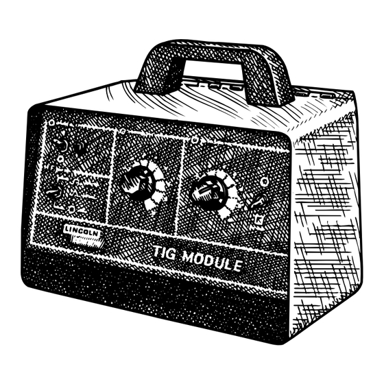
Page 32: Control Panel
OPERATION POWER HIGH FREQUENCY CONTINUOUS START ONLY LINCOLN ELECTRIC 1 INPUT POWER SWITCH AND PILOT LIGHT - Turns the input power to the TIG Module on and off. Red pilot light indicates that input power is “on”. 2 HIGH FREQUENCY SWITCH - Used to select Continuous High Frequency, Start Only High Frequency, or High Frequency Off. -
Page 33: Rear Connections
1 WARNING INFORMATION - Important information regarding the safe installation, operation, and servicing of the TIG Module. 2 INPUT RECEPTACLE - For connecting the Control Cable from the power source. This receptacle contains the following circuits: Input power, power source contactor control (where applicable) and power source remote control (where applicable). -
Page 34: Ranger 8 Operation
RANGER 8 OPERATION The tables (Table 8 & 9) list the recommended switch and control settings for the TIG Module/Ranger 8 combination. The first table is for the Ranger 8, and the second for the Ranger 8 with the K892-1 Remote Kit installed. - Page 35 Arc Start Switch or Amptrol is pressed. – – CURRENT CURRENT CONTROL CONTROL SWITCH ADJUST TO SUIT 0-10 REMOTE (WITH AN AMPTROL) LOCAL (WITH AN ARC START SWITCH) CONTROL AT WELDER / REMOTE CONTROL REMOTE CONTROL TIG MODULE...
-
Page 36: Figure 9
THE HALF-WAY POINT. THE CURRENT CAN BE VARIED FROM MINIMUM TO MAXIMUM OF THE RANGER SETTING BECAUSE THE CURRENT CONTROL KNOB IS SET TO MAXIMUM. TIG MODULE OPERATION WELDER SETTINGS RANGE OUTPUT CONTROL AT WELDER OUTPUT CONTROL REMOTE CHOOSE REMOTE OUTPUT CONTROL. -
Page 37: Ranger 9 Operation
K930-[ ] SETTINGS CURRENT AFTERFLOW CONTROL ADJUST ADJUST TO SUIT, TO SUIT 5 - 55 SECONDS RANGER 9 SETTINGS CONTROL AT WELDER / REMOTE RANGE CONTROL SELECT TO SUIT, 45 - 250 SELECT TO SUIT, REMOTE 45-160 CONTROL – –... -
Page 38: Ranger 10 & Ranger 300 D Operation
RANGER 10 / RANGER 300 D OPERATION The table (Table 11) lists the recommended switch and control settings for the TIG Module/Ranger 10 or TIG Module/Ranger 300 D combination. Make sure all connections are tight before proceeding. Operate the Ranger 10 or Ranger 300 D in accordance with the proper Operator’s Manual. -
Page 39: Ranger 10-Lx & Ranger 300 Dlx Operation
RANGER 10-LX / RANGER 300 DLX OPERATION The table (Table 12) lists the recommended switch and control settings for the TIG Module/Ranger 10-LX or TIG Module/Ranger 300 DLX combination. Make sure all connections are tight before proceeding. Operate the Ranger 10-LX or Ranger 300 DLX in accordance with the proper Operator’s Manual. -
Page 40: Operation On Other Lincoln Power Sources
OPERATION ON OTHER LINCOLN POWER SOURCES The table (Table 13) lists the recommended switch and control settings for the TIG Module when used with various Lincoln power sources. Operate the power source in accordance with its Manual. Note that AC power sources must be derated approximately 50% when used for AC TIG welding. -
Page 41: Tig Welding Information
TIG WELDING INFORMATION TYPICAL CURRENT RANGES DCEP ( + ) DCEN ( - ) Tungsten Electrode 1%, 2% 1%, 2% Thoriated Thoriated Diameter in. (mm) Tungsten Tungsten .010 (.25) 2-15 0.020 (.50) 5-20 0.040 (1.0) 15-80 1/16 (1.6) 70-150 10-20 3/32 (2.4) 150-250... -
Page 42: Accessories
OPTIONS / ACCESSORIES The following field installed Kits and accessories may be used dependingon the application: K936 Control Cables At least one of the following control cables is needed to connect the TIG Module to the power source. Four different cables are available. The proper choice of cable depends on the power source being used. -
Page 43: Maintenance
0.015(.38mm) inches. This setting is proper for most applications. To adjust the spark, first be sure that the Ranger welder is off, and that the input cable is disconnected from the Input Receptacle on the back of the TIG Module. Remove the outer case... -
Page 44: Troubleshooting
How To Use Troubleshooting Guide This Troubleshooting Guide is designed to be used by the machine Owner/Operator. Unauthorized repairs performed on this equipment may result in danger to the technician and machine operator and will invalidate your factory warranty. For your safety, please observe all safety notes and precautions detailed in the Safety Section of this manual to avoid electrical shock or danger while troubleshooting this equipment. -
Page 45: Troubleshooting Guide
CAUSE OUTPUT PROBLEMS 1. Contact your local Lincoln Authorized Field Service Facility 1. Make certain that the welder power source has weld output- Check for open circuit voltage at welding power source 2. Make certain that the tungsten type and size is correct for the process 3. - Page 46 2. Make certain both the TIG Module and the welding power source are powered up 1. Make certain the welder power source is in the remote control mode 2. The current control (R4) may be set too low for the process CAUTION –...
- Page 47 Troubleshooting Guide PROBLEMS (SYMPTOMS) High frequency not present or intermittent at torch electrode High frequency not present at spark High Frequency stays on after the arc is established If for any reason you do not understand the test procedures or are unable to perform the tests/repairs safely, contact your local Authorized Field Service Facility for technical troubleshooting assistance before you proceed.
-
Page 48: Wiring Diagram
WIRING DIAGRAM FOR CODES 10135, 10203 and 10284 HIGH VOLTAGE CAPACITOR .0025/10KV OPTIONAL CONTACTOR L1,L2 HI-FREQ. INDUCTOR PILOT LIGHT BLEEDER RESISTOR 150/100W AFTERFLOW TIME POTENTIOMETER 500K/2W CURRENT CONTROL POTENTIOMETER 10K/2W POWER SWITCH HIGH FREQUENCY SWITCH CURRENT CONTROL SWITCH GAS SOLENOID VALVE OPTIONAL WATER SOLENOID VALVE HIGH VOLTAGE TRANSFORMER HIGH FREQUENCY TRANSFORMER... - Page 49 WIRING DIAGRAM WIRING DIAGRAM FOR CODE 11010 POWER SWITCH HIGH FREQUENCY SWITCH CURRENT CONTROL SWITCH GAS SOLENOID VALVE OPTIONAL WATER SOLENOID VALVE HIGH VOLTAGE TRANSFORMER HIGH FREQUENCY TRANSFORMER LEAD COLORING CODE: COMPONENT VALUE UNITS: B- BLACK CAPACITOR: MFD/VOLTS G- GREEN RESISTOR: OHMS/WATTS N- BROWN R- RED...
- Page 50 NOTES...
- Page 51 NOTES...
- Page 52 ● Do not touch electrically live parts or WARNING electrode with skin or wet clothing. ● Insulate yourself from work and ground. Spanish ● No toque las partes o los electrodos AVISO DE bajo carga con la piel o ropa mojada.
- Page 53 ● ● Keep your head out of fumes. Turn power off before servicing. ● Use ventilation or exhaust to remove fumes from breathing zone. ● Los humos fuera de la zona de ● Desconectar el cable de respiración. alimentación de poder de la ●...
- Page 54 • World's Leader in Welding and Cutting Products • • Sales and Service through Subsidiaries and Distributors Worldwide • Cleveland, Ohio 44117-1199 U.S.A. TEL: 216.481.8100 FAX: 216.486.1751 WEB SITE: www.lincolnelectric.com...
Need help?
Do you have a question about the TIG MODULE IM528-B and is the answer not in the manual?
Questions and answers
Can I use this on a Lincoln electric commander 300?