Table of Contents
Advertisement
RETURN TO MAIN MENU
IM586-B
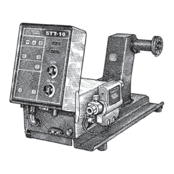
STT- 10 Head & Controls
August, 2007
Boom Mount or Bench Models
For use with: STT-10 Control - Boom Mount Code 10447, 10832
10 Series Wire Drive - Boom Mount Code 10443, 10763, 10818
STT-10 Boom Package Code 10448
Synergic 7F Wire Drive Code 10190, 10191
STT-10 - Bench Model Code 10446, 10766, 10821
STT-10 - Zipline Boom Package Code 10499, 10500, 10773
Safety Depends on You
Lincoln arc welding and cutting
equipment is designed and built
with safety in mind. However, your
overall safety can be increased by
proper installation ... and thought-
ful operation on your part. DO
NOT INSTALL, OPERATE OR
REPAIR THIS EQUIPMENT
WITHOUT
READING
THIS
MANUAL AND THE SAFETY
PRECAUTIONS CONTAINED
THROUGHOUT. And, most
importantly, think before you act
and be careful.
OPERATOR'S MANUAL
Copyright © 2007 Lincoln Global Inc.
• World's Leader in Welding and Cutting Products •
• Sales and Service through Subsidiaries and Distributors Worldwide •
Cleveland, Ohio 44117-1199 U.S.A. TEL: 216.481.8100 FAX: 216.486.1751 WEB SITE: www.lincolnelectric.com
Advertisement
Table of Contents
Troubleshooting

Related Manuals for Lincoln Electric STT-10 HEAD & CONTROLS BOOM MOUNT OR BENCH MODELS IM586-B


Summary of Contents for Lincoln Electric STT-10 HEAD & CONTROLS BOOM MOUNT OR BENCH MODELS IM586-B
- Page 1 RETURN TO MAIN MENU IM586-B STT- 10 Head & Controls August, 2007 Boom Mount or Bench Models For use with: STT-10 Control - Boom Mount Code 10447, 10832 10 Series Wire Drive - Boom Mount Code 10443, 10763, 10818 STT-10 Boom Package Code 10448 Synergic 7F Wire Drive Code 10190, 10191 STT-10 - Bench Model Code 10446, 10766, 10821 STT-10 - Zipline Boom Package Code 10499, 10500, 10773...
-
Page 2: California Proposition 65 Warnings
351040, Miami, Florida 33135 or CSA Standard W117.2-1974. A Free copy of “Arc Welding Safety” booklet E205 is available from the Lincoln Electric Company, 22801 St. Clair Avenue, Cleveland, Ohio 44117-1199. BE SURE THAT ALL INSTALLATION, OPERATION, MAINTENANCE AND REPAIR PROCEDURES ARE PERFORMED ONLY BY QUALIFIED INDIVIDUALS. -
Page 3: Electric Shock Can Kill
ELECTRIC SHOCK can kill. 3.a. The electrode and work (or ground) circuits are electrically “hot” when the welder is on. Do not touch these “hot” parts with your bare skin or wet clothing. Wear dry, hole-free gloves to insulate hands. - Page 4 WELDING and CUTTING SPARKS can cause fire or explosion. 6.a. Remove fire hazards from the welding area. If this is not possible, cover them to prevent the welding sparks from starting a fire. Remember that welding materials from welding can easily go through small cracks and openings to adjacent areas.
- Page 5 PRÉCAUTIONS DE SÛRETÉ Pour votre propre protection lire et observer toutes les instructions et les précautions de sûreté specifiques qui parraissent dans ce manuel aussi bien que les précautions de sûreté générales suiv- antes: Sûreté Pour Soudage A LʼArc 1. Protegez-vous contre la secousse électrique: a.
-
Page 6: On-Line Product Registration
Electric for advice or information about their use of our products. We respond to our customers based on the best information in our posses- sion at that time. Lincoln Electric is not in a position to warrant or guarantee such advice, and assumes no liability, with respect to such infor- mation or advice. -
Page 7: Table Of Contents
Installation ...Section A Technical Specifications ...A-1 General Description...A-2 Recommended Processes and Equipment ...A-2 Installation of the STT-10 Boom Mount Wire Feeder Components...A-2 Mounting the 10 Series Wire Drive Unit ...A-2 Mounting Synergic 7F Wire Drive Unit ...A-3 Mounting the STT-10 Control Box ...A-3 Connecting Wire Drive Unit to Control Box ...A-3 Electrode Routing...A-4 Wire Drive Speed Range Selection ...A-4... -
Page 8: Table Of Contents
TABLE OF CONTENTS Page Diagrams ...Section F Wiring (STT-10 Control)...F-1 Wiring (10 Series Wire Drive) ...F-2, F3 Dimension Prints ...F-4 thru F-6 Parts List...P312 Series... -
Page 9: Installation
TECHNICAL SPECIFICATIONS – STT-10 Heads & Controls WIRE DRIVE OR WIRE DRIVE SECTION OF FEEDER SPEC.# TYPE LOW SPEED RATIO Speed K1563-1Δ, 10 Series 35-500 IPM K1563-3 Boom Mount (0.89-12.7 m/m) K679-1 Synergic 7F* 50 - 770 IPM Std Drive Boom Mount (1.27 - 19.5 m/m) K679-2 Synergic 7F*... -
Page 10: Recommended Processes And Equipment
The 10 Series Wire Drive assemblies include a heavy duty head with an externally changeable gear ratio and 4 driven roll drives housed together in a single combination mounting and connection box. Gun adapters are available to permit use with a variety of standard welding guns. Available Models: The STT-10 Wire Feeder system is available configured in both Bench and Boom models. -
Page 11: Mounting Synergic 7F Wire Drive Unit
Mounting Synergic 7F Wire Drive Unit Mount the wire feed unit by means of the insulated mounting bracket attached to the bottom of the gearbox. Reference L9777 (included with Drive unit) to find the size and location of the mounting holes. The gearbox assembly is electrically “hot”... -
Page 12: Electrode Routing
Electrode Routing The electrode supply may be either from reels, Readi- Reels, spools, or bulk packaged drums or reels. Observe the following precautions: a) The electrode must be routed to the wire drive unit so that the bends in the wire are at a minimum, and also that the force required to pull the wire from the reel into the wire drive unit is kept at a minimum. -
Page 13: Wire Feed Drive Roll Kits
WIRE FEED DRIVE ROLL KITS NOTE: The maximum rated solid and cored wire sizes for each wire drive head and selected drive ratio is shown on the SPECIFICATIONS in the front of this section. The electrode sizes that can be fed with each roll and guide tube are stenciled on each part. -
Page 14: Gun Connection-General
6) Install each drive roll by pushing over shaft until it butts up against locating shoulder on the drive roll shaft. (Do Not exceed maximum wire size rating of the wire drive). 7) Install Outer Wire Guide by sliding over locating pins and tightening in place. -
Page 15: Gun Cable Connection With Fast-Mate Connection
• Keep cylinder upright and chained to support. • Keep cylinder away from areas where it may be damaged. • Never lift welder with cylinder attached. • Never allow welding electrode to touch cylinder. • Keep cylinder away from welding or other live elec- trical circuits. -
Page 16: Electrical Installation
ELECTRICAL INSTALLATION WARNING ELECTRIC SHOCK can kill. • Do not touch electrically live parts such as output terminals or internal wiring. • When inching with gun trigger, electrode and drive mechanism are “hot” to work and ground and could remain energized several seconds after the gun trigger is released. -
Page 17: Optional Features Installation
When installed and properly configured, the K1561-1 Robotics Interface Module allows complete control of the welding process from the robot controller. The Lincoln Electric Companyʼs Automation Center should be contacted for questions regarding installa- tion or operation of the Robotics Interface Module. -
Page 18: Operation
OPERATING INSTRUCTIONS Safety Precautions WARNING ELECTRIC SHOCK can kill. • Do not touch electrically live parts such as output terminals or internal wiring. • Unless using cold feed feature when inch- ing with gun trigger, electrode and drive mech- anism are “hot” to work and ground and could remain energized several seconds after the gun trigger is released. -
Page 19: Keypad And Display Operation
4-Step Trigger Mode Operation Selection The STT-10 Control is set up for 4-Step Trigger mode operation with or without weld current interlock by set- ting S1 DIP switch 5 (Labeled “4”). When 4-Step trigger mode is selected on the STT-10 keypad (See Keypad and Display Operation in this section) S1 DIP switch setting determines the 4-step trigger operation:... -
Page 20: Operation Keys
BACKGROUND MAX SPOT BACKGROUND MIN BURNBACK POSTFLOW RANGE CONTROL THE LINCOLN ELECTRIC COMPANY CLEVELAND, OHIO U.S.A. Keypad and Display Description Keypad - Eight key, membrane type with "snap" tac- tile feel and embossed domes. Long life design. Spatter resistant surface. -
Page 21: Trigger Mode Selection
Trigger Mode Selection Trigger Mode Select key COLD FEED - enables operator to TRIGGER 2-STEP STD choose mode of operation 4-STEP LOCK shown by the indicator lights. Pressing key caus- SPOT mode sequence (top to bottom) starting from the current indicated selection. -
Page 22: Acceleration Selection
Range Select key - enables operator to RANGE choose which weld parameter to set the maxi- mum or minimum range. Pressing the key causes the range mode lights to sequence (top to bottom) starting from the current indicated selection. The range settings can be set inde- pendently for each procedure. -
Page 23: Wire Reel Loading
WIRE REEL LOADING - READI-REELS, SPOOLS OR COILS To Mount a 30 Lb. (14 kg) Readi-Reel Package (Using the Molded Plastic K363-P Readi-Reel Adapter:) The Spindle should be located in the LOWER mounting hole. 1) Depress the Release Bar on the Retaining Collar and remove it from the spindle. -
Page 24: Feeding Electrode And Brake Adjustment
To Mount a 50-60 Lb. (22.7-27.2 kg) Coil: (Using K1504-1 Coil Reel) (For 50-60 lb Readi- Reels a K438 Readi-Reel Adapter must be used). The Spindle must be located in the UPPER mounting hole. 1) With the K1504-1 Coil Reel mounted on to the 2" (51 mm) spindle (or with reel laying flat on the floor) loosen the spinner nut and remove the reel cover. -
Page 25: Procedure For Setting Angle Of Feedplate
1) Press end of gun against a solid object that is electrically isolated from the welder output and press the gun trigger for several seconds. 2) If the wire "birdnests", jams, or breaks at the drive roll, the drive roll pressure is too great. Back the pressure setting out 1/2 turn, run new wire through gun, and repeat above steps. -
Page 26: Wire Reel Changing
WIRE REEL CHANGING At the end of a coil, remove the last of the old electrode coil from the conductor cable by either pulling it out at the nozzle end of the gun or by using the following pro- cedure: 1) Cut the end of the electrode off at the gun end. -
Page 27: Accessories
TABLE C.1 – DRIVE ROLL AND GUIDE TUBE KITS Wire Size Solid & (Cored) Steel Electrode 0.023” - 0.025” (0.6 mm) 0.030” (0.8 mm) 0.035” (0.9 mm) 0.040” (1.0 mm) 0.040” (1.0 mm) 0.045” (1.2 mm) 0.045”(Cored) (1.2 mm) 0.052” (1.4 mm) ACCESSORIES 4-Roll... -
Page 28: Spindle Adapters
K1561-1 Robotics Interface Module allows complete control of the weld- ing process form the robot controller. The Lincoln Electric Companyʼs Automation Center should be contacted for questions regarding installa- tion or operation of the Robotics Interface Module. - Page 29 Coil Adapter: K1504-1 Permits 50 lb to 60 lb (22.7-27.2 Kg.) Coils to be mounted on 2: (51 mm) O.D. spindles. K435 Permits 14 lb. (6 kg) Innershield coils to be mounted on 2" (51 mm) O.D. spindles. K468 Permits 8" (203 mm) O.D. spools to be mounted on 2"...
-
Page 30: Gun And Cable Assemblies
GUN AND CABLE ASSEMBLIES The following Lincoln gun and cable assemblies are compatible with 10 Series Wire Feed heads with appropriate K1500 Gun Adapter: K126 (Requires K1500-1) Innershield gun and cable assemblies are rated at 350 amps, 60% duty cycle. (Consult sales specifications for appropriate models) K115 (Requires K1500-1) Innershield gun and cable... -
Page 31: Maintenance
MAINTENANCE Safety Precautions WARNING ELECTRIC SHOCK can kill. • Do not touch electrically live parts such as output terminals or internal wiring. • When inching with gun trigger, electrode and drive mechanism are “hot” to work and ground and could remain energized several seconds after the gun trigger is released. -
Page 32: How To Use Troubleshooting Guide
HOW TO USE TROUBLESHOOTING GUIDE Service and Repair should only be performed by Lincoln Electric Factory Trained Personnel. Unauthorized repairs performed on this equipment may result in danger to the technician and machine operator and will invalidate your factory warranty. For your safety and to avoid Electrical Shock, please observe all safety notes and precautions detailed throughout this manual. -
Page 33: Troubleshooting
Observe all Safety Guidelines detailed throughout this manual PROBLEMS (SYMPTOMS) Rough wire feeding or wire not feed- ing, but drive rolls are turning. Variable or "hunting" arc. Poor arc striking with sticking or "blast-offs", weld porosity, narrow and ropy looking bead, or electrode stubbing into the plate while welding. - Page 34 Observe all Safety Guidelines detailed throughout this manual PROBLEMS (SYMPTOMS) Motor does not turn when trigger is pulled. The drive motor does not turn although arc voltage is present and the gas solenoid is on. No control of wire feed speed. Motor turns.
- Page 35 Observe all Safety Guidelines detailed throughout this manual PROBLEMS (SYMPTOMS) Gas purge key does not operate the gas solenoid, but gas flow does occur while welding. Pressing the current key does not select between the peak and back- ground current LEDʼs. Pressing the procedure key does not select between A - Remote - B.
- Page 36 Observe all Safety Guidelines detailed throughout this manual PROBLEMS (SYMPTOMS) Pressing the trigger key has no effect while not welding. Pressing the control key has no effect while not welding. One of the knobs changes the dis- play, but the other doesnʼt. Neither knob changes the display.
- Page 37 Observe all Safety Guidelines detailed throughout this manual PROBLEMS (SYMPTOMS) Displays & LEDʼs on keypad are off. The green and red LEDʼs on the control p.c. board are both blinking at about one second intervals. Displays & LEDʼs on keypad are off.
-
Page 38: Electric Shock
PC board. If there is damage to the PC board or if replacing PC board corrects problem, return it to the local can kill. Lincoln Electric Field Service Shop. CAUTION STT-10... - Page 39 DIAGRAMS STT-10...
- Page 40 DIAGRAMS STT-10...
- Page 41 DIAGRAMS STT-10...
-
Page 42: Connection Diagrams
CONNECTION DIAGRAMS STT-10... -
Page 43: Dimension Print
DIAGRAMS DIMENSION PRINT STT-10... - Page 44 DIAGRAMS DIMENSION PRINT STT-10...
- Page 45 DIAGRAMS DIMENSION PRINT STT-10...
- Page 46 NOTES STT-10...
- Page 47 NOTES STT-10...
- Page 48 ● WARNING ● Spanish ● AVISO DE PRECAUCION ● French ● ATTENTION ● ● German WARNUNG ● Portuguese ● ATENÇÃO ● Japanese Chinese Korean Arabic ● ● ● ● ● ● ● ● ● ●...
- Page 49 ● ● ● ● ● ● ● ● ● ● ● ● ● ● ● ● ● ● Spanish ● PRECAUCION French ● ATTENTION ● German WARNUNG Portuguese ● ● Japanese Chinese Korean Arabic WARNING AVISO DE ATENÇÃO...
- Page 50 • World's Leader in Welding and Cutting Products • • Sales and Service through Subsidiaries and Distributors Worldwide • Cleveland, Ohio 44117-1199 U.S.A. TEL: 216.481.8100 FAX: 216.486.1751 WEB SITE: www.lincolnelectric.com...
Need help?
Do you have a question about the STT-10 HEAD & CONTROLS BOOM MOUNT OR BENCH MODELS IM586-B and is the answer not in the manual?
Questions and answers