
Related Manuals for SMA SUNNY BOY 1300TL


Summary of Contents for SMA SUNNY BOY 1300TL
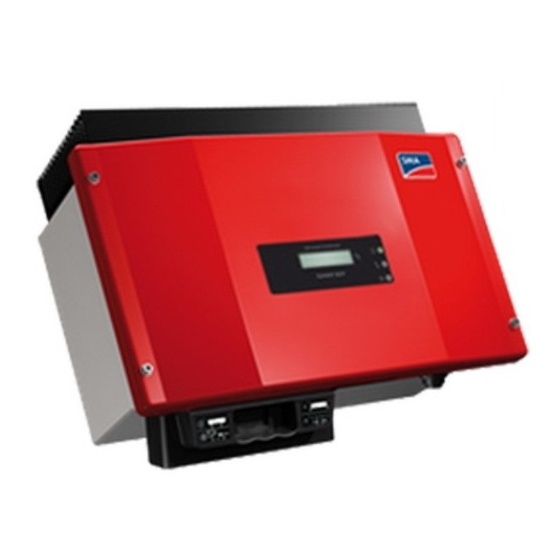
- Page 1 PV Inverter SUNNY BOY 1300TL/1600TL/2100TL Installation Guide SB13_21TL-IA-IEN121060 | IME-SB21TL | Version 6.0...
-
Page 3: Table Of Contents
SMA Solar Technology AG Table of Contents Table of Contents Information on this Manual......7 Validity ..........7 Target Group . - Page 4 SMA Solar Technology AG Table of Contents Setting the Display Language ......28 Connecting the PV Array (DC) ......29 5.4.1...
- Page 5 11.1 Sunny Boy 1300TL ........59 11.2 Sunny Boy 1600TL .
- Page 6 Table of Contents SMA Solar Technology AG SB13_21TL-IA-IEN121060 Installation Guide...
-
Page 7: Information On This Manual
You will find further information on special topics such as designing a miniature circuit-breaker or the description of the operating parameters in the download area at www.SMA.de/en. Refer to the User Manual provided for detailed information on operating the inverter. -
Page 8: Symbols Used
Information on this Manual SMA Solar Technology AG 1.4 Symbols Used The following types of safety instructions and general information are used in this manual: DANGER! "DANGER" indicates a hazardous situation which, if not avoided, will result in death or serious injury. -
Page 9: Safety
Do not use the Sunny Boy for purposes other than those described here. Alternative uses, modifications to the Sunny Boy or the installation of components not expressly recommended or sold by SMA Solar Technology AG shall void any warranty claims and the operation permission. Installation Guide... -
Page 10: Safety Instructions
Safety SMA Solar Technology AG 2.2 Safety Instructions DANGER! Danger to life due to high voltages in the inverter. • All work on the inverter may only be carried out by an electrically skilled person. • The appliance is not to be used by children or persons with reduced physical, sensory or mental capabilities, or lack of experience and knowledge, unless they have been given supervision or instruction. -
Page 11: Explanation Of Symbols
Safety Grounding the PV array Comply with the local regulations for grounding the modules and the PV array. SMA Solar Technology AG recommends connecting the array frame and other electrically conductive surfaces so that there is continuous conduction and to ground them in order to ensure maximum protection for plants and persons. -
Page 12: Symbols On The Type Label
SMA Solar Technology AG Safety 2.3.2 Symbols on the Type Label Symbol Explanation Beware of dangerous electrical voltage. The inverter operates at high voltages. All work on the inverter may only be carried out by an electrically skilled person. Beware of hot surface. -
Page 13: Unpacking
Wall mounting bracket Electronic Solar Switch (ESS)* DC connectors Sunny Boy 1300TL/1600TL: 2 units (1 x positive, 1 x negative) Sunny Boy 2100TL: 4 units (2 x positive, 2 x negative) Sealing plugs for DC connectors Sunny Boy 1300TL/1600TL: 2 units... -
Page 14: Identifying The Inverter
Unpacking SMA Solar Technology AG 3.2 Identifying the Inverter You can identify the inverter by the type label. The type label is on the right side of the enclosure. The serial number (Serial No.) and the type (Type/Model) of the inverter, as well as device-specific characteristics, are specified on the type label. -
Page 15: Assembly
SMA Solar Technology AG Assembly 4 Assembly 4.1 Safety DANGER! Danger to life due to fire or explosion. Despite careful construction, electrical devices can cause fires. • Do not mount the inverter on flammable construction materials. • Do not mount the inverter in areas where highly flammable materials are stored. - Page 16 Assembly SMA Solar Technology AG • Never mount the device with a forward tilt. • Never install the device with a sideways tilt. • Do not mount horizontally. • Install at eye level in order to allow operating states to be read at all times.
-
Page 17: Mounting The Inverter With The Wall Mounting Bracket
SMA Solar Technology AG Assembly 4.3 Mounting the Inverter with the Wall Mounting Bracket CAUTION! Risk of injury due to the heavy weight of the inverter. • Take the inverter's weight of approx. 16 kg into account for mounting. • Use mounting material suitable for the surface when attaching the wall mounting bracket. - Page 18 SMA Solar Technology AG Assembly 3. Mount the inverter with its upper fastening plates on the wall mounting bracket in such a way that it cannot slide out of the bracket sideways. 4. If a second protective conductor is required in the country of installation, ground the inverter and fix it securely, as described in section 5.2.3 "Connecting...
-
Page 19: Electrical Connection
Object Description DC connectors for connecting the strings Sunny Boy 1300TL/1600TL: connection for 1 string Sunny Boy 2100TL: connection for 2 strings Socket for connecting the Electronic Solar Switch (ESS) DC switch-disconnector* Enclosure opening with filler-plugs for communication Socket for AC connection... -
Page 20: Interior View
Socket for AC connection Flat male tab for grounding the cable shield during RS485 communication DC connectors for connecting the strings Sunny Boy 1300TL/1600TL: connection for 1 string Sunny Boy 2100TL: connection for 2 strings Electronic Solar Switch (ESS) socket*... -
Page 21: Connection To The Power Distribution Grid (Ac)
100 mA or higher. You will find detailed information for using an RCD in the Technical Description "Criteria for Selecting an RCD" in the download area at www.SMA.de/en. Cable Sizing Select a cable diameter that does not lead to cable losses of more than 1 % at rated output power. -
Page 22: Cable Requirements
The maximum permissible rating can be found in section 11 "Technical Data" (page 59). Detailed information and examples for the rating of a miniature circuit-breaker can be found in the Technical Description "Line Circuit Breaker" in the SMA Solar Technology AG download area at www.SMA.de/en. DANGER! Danger to life due to fire. - Page 23 SMA Solar Technology AG Electrical Connection DANGER! Danger to life due to fire. When a producer (inverter) and a consumer are connected to the same miniature circuit-breaker, the protective function of the miniature circuit-breaker is no longer guaranteed. The current from the inverter and the grid can accumulate to form overcurrents that are not detected by the miniature circuit-breaker.
-
Page 24: Connecting The Inverter To The Power Distribution Grid (Ac)
AC nom The exact operating range of the inverter is specified in the operation parameters. The corresponding document can be found in the download area at www.SMA.de/en, in the "Technical Description" category of the respective inverter. 3. Switch off the miniature circuit-breaker, ensure that the device cannot be unintentionally or accidentally reconnected, and make sure no voltage is present. - Page 25 SMA Solar Technology AG Electrical Connection 7. Attach the pressure screw or cable gland and the threaded sleeve. Size used Procedure PG13.5 • Push the sealing ring into the fastening case. • Slide the PG13.5 pressure screw and the fastening case including the sealing ring over the AC cable.
- Page 26 Electrical Connection SMA Solar Technology AG 13. Screw the threaded sleeve onto the socket element. 14. Tighten the pressure screw or cable gland tightly onto the threaded sleeve. Size used Procedure PG13.5 The fastening case along with the sealing ring is pressed into the threaded sleeve and can no longer be seen.
-
Page 27: Connecting Additional Grounding
SMA Solar Technology AG Electrical Connection 5.2.3 Connecting Additional Grounding If a second protective conductor, additional grounding or equipotential bonding is required, you can additionally ground the inverter on the enclosure. Overview of the Additional Grounding Object Description M6x12 cylinder head screw (included in the scope of delivery) -
Page 28: Setting The Display Language
SMA Solar Technology AG Electrical Connection 5.3 Setting the Display Language You can set the language of the display using the switches underneath the display assembly inside the inverter. Procedure 1. Open the inverter as described in section 7.2 "Opening the Inverter" (page 39). -
Page 29: Connecting The Pv Array (Dc)
SMA Solar Technology AG Electrical Connection 5.4 Connecting the PV Array (DC) 5.4.1 Conditions for the DC Connection Use of Adaptors Adaptors (branch plug connectors) must not be visible or freely accessible in the immediate surroundings of the inverter. • The DC circuit may not be interrupted by adaptors. -
Page 30: Assembling The Dc Connector
Electrical Connection SMA Solar Technology AG 5.4.2 Assembling the DC Connector In order to be connected to the inverter, all connection cables of the PV modules must be equipped with the DC connectors provided. To assemble the DC connectors, proceed as follows. Ensure the connectors have the correct polarity. - Page 31 SMA Solar Technology AG Electrical Connection 3. Ensure the cable is correctly in place. Result Measure ☑ If the conductors are visible in the hollow • Proceed to step 4. cavity of the clamping clip, the cable is in the correct position.
-
Page 32: Opening The Dc Connector
Electrical Connection SMA Solar Technology AG 5.4.3 Opening the DC Connector 1. Unscrew the bolted connection. 2. To open the connector, insert a screwdriver into the side catch and pry it open. For this purpose, use a screwdriver with a width of 3.5 mm. -
Page 33: Connecting The Pv Array (Dc)
SMA Solar Technology AG Electrical Connection 5.4.4 Connecting the PV Array (DC) DANGER! Danger to life due to high voltages in the inverter. • Before connecting the PV array, ensure that the miniature circuit-breaker is switched off. NOTICE! Excessive voltages can destroy the measuring device. - Page 34 SMA Solar Technology AG Electrical Connection NOTICE! Exceeding the maximum input voltage can destroy the inverter. If the voltage of the PV modules exceeds the maximum input voltage of the inverter, it can be destroyed by the overvoltage. This will void all warranty claims.
-
Page 35: Communication
SMA Solar Technology AG Electrical Connection – Insert the DC connectors with sealing plugs into the corresponding DC inputs on the inverter. 7. If an Electronic Solar Switch is installed, check it for wear, as described in section 8.1 "Checking the Electronic Solar Switch for Wear"... -
Page 36: Setting The Grid And Country Parameters
To change grid-relevant parameters, you need a personal access code - the so-called SMA Grid Guard Code. The application form for the personal access code is available in the download area at www.SMA.de/en, in the "Certificate" category of the respective inverter. -
Page 37: Commissioning
SMA Solar Technology AG Commissioning 6 Commissioning 6.1 Commissioning the Inverter 1. Check the following requirements before commissioning: – The inverter is firmly in place – Correct connection of the AC cable (grid) – All DC cables connected (strings) – Unnecessary DC inputs are closed with the corresponding DC connectors and sealing plugs –... -
Page 38: Display Messages During The Startup Phase
Commissioning SMA Solar Technology AG 6.2 Display Messages during the Startup Phase • After commissioning, the inverter displays the SB xxx device type in the startup phase. Wrxxx • After 5 seconds or when you tap on the enclosure lid again, the firmware version of the internal processors is displayed by the inverter. -
Page 39: Opening And Closing
SMA Solar Technology AG Opening and Closing 7 Opening and Closing 7.1 Safety DANGER! Risk of lethal electric shock. Before opening the inverter observe the following: • Ensure that no voltage is present on the AC side • Ensure that neither voltage nor current is present on the DC side. - Page 40 Opening and Closing SMA Solar Technology AG 5. Unlock all DC connectors. For this purpose, use a screwdriver with a width of 3.5 mm. – Insert the screwdriver into one of the side slits (1). – Disconnect DC connectors (2).
- Page 41 SMA Solar Technology AG Opening and Closing 7. Check whether all LEDs and the display have gone out. DANGER! Danger to life due to high voltages in the inverter. The capacitors in the inverter require 15 minutes to discharge. • Wait 15 minutes before opening the inverter.
-
Page 42: Closing The Inverter
SMA Solar Technology AG Opening and Closing 7.3 Closing the Inverter 1. Establish the protective conductor (PE) connection to the lid. 2. Secure the enclosure lid of the inverter by evenly tightening the 4 lid screws. 3. Attach the AC plug. - Page 43 SMA Solar Technology AG Opening and Closing 6. If an external DC switch-disconnector is available, connect it. 7. If an Electronic Solar Switch is installed, check it for wear, as described in section 8.1 "Checking the Electronic Solar Switch for Wear" (page 44), and reattach it firmly.
-
Page 44: Maintenance And Cleaning
SMA Solar Technology AG Maintenance and Cleaning 8 Maintenance and Cleaning Check the correct operation of the inverter at regular intervals. Dirt such as dust or pollen can cause heat concentration that can lead to yield losses. Also check the inverters and the cables for visible external damage. - Page 45 SMA Solar Technology AG Maintenance and Cleaning Result Measure ☑ The metal tongues in the Electronic Solar The Electronic Solar Switch can no longer reliably Switch have a brown discoloration or are disconnect the DC supply. burned through (A). 1. Replace the Electronic Solar Switch handle before attaching it again (for the order number see section 12 "Accessories"...
-
Page 46: Failure Search
Do not perform any repairs that are not described here and instead take advantage of the 24-hour replacement service (inverter ready for shipping and handed over to a freight-forwarding company within 24 hours) and the SMA Solar Technology AG repair service. 9.1 Blink Codes... -
Page 47: Error Messages
Bfr-Srr Internal measurement comparison fault or hardware defect. Corrective measures • If this fault continues to occur, contact the SMA Serviceline. Fault current The inverter has detected a drastic change in the differential current. The integrated differential current monitoring system plays an important part dI-Srr in ensuring personal safety. - Page 48 There is a grid fault ("Bfr" or "Srr" is an internal message of no relevance for the user). Iac-DC_Offs-Bfr Corrective measures • Check the grid conditions. • Contact the SMA Serviceline if this fault occurs frequently or repeatedly. SB13_21TL-IA-IEN121060 Installation Guide...
- Page 49 Corrective measures • Check the plant design and grid conditions. K1-Close Error during relay test. Corrective measures K1-Open • Contact the SMA Serviceline if this fault occurs frequently or K2-Open repeatedly. MSD-dI Internal measurement comparison fault or hardware defect. Corrective measures MSD-Fac •...
- Page 50 If the message reappears, disconnect the inverter again and contact the SMA Serviceline (see section 13 "Contact" (page 72)). Vinternal The internal hardware monitor has detected an overvoltage condition in the intermediate circuit of the inverter. Corrective measures • If this fault continues to occur, contact the SMA Serviceline. SB13_21TL-IA-IEN121060 Installation Guide...
- Page 51 Watchdog Internal program run fault. Corrective measures • If this fault continues to occur, contact the SMA Serviceline. Zac-Bfr The grid impedance is no longer within the permissible range ("Bfr" or "Srr" is an internal message of no relevance for the user). For safety Zac-Srr reasons, the inverter disconnects itself from the grid.
-
Page 52: Red Led Is Glowing Continuously
SMA Solar Technology AG Failure Search 9.3 Red LED is Glowing Continuously If the red status display LED lights up continuously during operation, there is a ground fault in the PV array, at least one varistor for overvoltage protection is defective or there is an insulation fault. - Page 53 SMA Solar Technology AG Failure Search 4. Measure the voltages between the plus pole and the minus pole of each string. ☑ A ground fault exists if the measured voltages are stable and the sum of the voltages from the plus pole to the ground potential and from the minus pole to the ground potential of a string are almost the same as the voltage between the plus and minus poles.
-
Page 54: Checking The Function Of The Varistors
SMA Solar Technology AG Failure Search The approximate position of the ground fault can be determined from the ratio of the measured voltages between the plus pole against ground potential (PE) and the minus pole against ground potential (PE). Example: The ground fault is between the second and third module in this case. - Page 55 The varistors are specially manufactured for use in the inverter and are not commercially available. They must be ordered directly from SMA Solar Technology AG (see section 12 "Accessories" (page 71)). • To replace the varistors, proceed to step 3.
- Page 56 ☑ The terminals will loosen. If you do not receive an insertion tool for operating the terminals with your replacement varistors, contact SMA Solar Technology AG. As an alternative, the individual terminal contacts can be operated using a 3.5 mm wide screwdriver.
-
Page 57: Decommissioning
SMA Solar Technology AG Decommissioning 10 Decommissioning 10.1 Disassembling the Inverter CAUTION! Risk of injury due to the heavy weight of the inverter. • Note that the inverter weighs approx. 16 kg. 1. Open the inverter as described in section 7.2 "Opening the Inverter" (page 39). -
Page 58: Packing The Inverter
Dispose of the inverter at the end of its service life in accordance with the disposal regulations for electronic waste which apply at the installation location at that time. Alternatively, send it back to SMA Solar Technology AG with shipping paid by sender, and labeled "ZUR ENTSORGUNG" ("for disposal") (see section 13 "Contact" (page 72)). -
Page 59: Technical Data
SMA Solar Technology AG Technical Data 11 Technical Data 11.1 Sunny Boy 1300TL DC Input Maximum DC power at cos φ = 1 1 400 W Maximum input voltage* 600 V MPP voltage range 125 V … 480 V Rated input voltage... -
Page 60: Protective Devices
Technical Data SMA Solar Technology AG Maximum cable length at cable diameter of 11 m 1.5 mm² Maximum cable length at cable diameter of 18 m 2.5 mm² Protective Devices DC reverse-polarity protection Short circuit diode Input-side disconnection device* Electronic Solar Switch... - Page 61 SMA Solar Technology AG Technical Data Country standards, as of 03/2012* VDE 0126-1-1 UTE C15-712 AS 4777 C10/11 PPDS EN 50438 G83/-1-1 RD1663/661-A * EN 50438: Does not apply to all country standard deviations of EN 50438 G83/-1-1: Valid from firmware version 4.20...
- Page 62 Technical Data SMA Solar Technology AG Torque Enclosure lid screws 6.0 Nm Additional grounding screw 6.0 Nm Cylinder head screw for attaching the enclosure 6.0 Nm to the wall mounting bracket SUNCLIX lock nut 2.0 Nm RS485 communication connection 1.5 Nm...
-
Page 63: Sunny Boy 1600Tl
SMA Solar Technology AG Technical Data 11.2 Sunny Boy 1600TL DC Input Maximum DC power at cos φ = 1 1 700 W Maximum input voltage* 600 V MPP voltage range 155 V … 480 V Rated input voltage 400 V... - Page 64 Technical Data SMA Solar Technology AG Maximum cable length at cable diameter of 11 m 1.5 mm² Maximum cable length at cable diameter of 18 m 2.5 mm² Protective Devices DC reverse-polarity protection Short circuit diode Input-side disconnection device* Electronic Solar Switch...
- Page 65 SMA Solar Technology AG Technical Data Country standards, as of 03/2012* VDE 0126-1-1 UTE C15-712 AS 4777 C10/11 PPDS EN 50438 G83/-1-1 RD1663/661-A * EN 50438: Does not apply to all country standard deviations of EN 50438 G83/-1-1: Valid from firmware version 4.20...
- Page 66 Technical Data SMA Solar Technology AG Torque Enclosure lid screws 6.0 Nm Additional grounding screw 6.0 Nm Cylinder head screw for attaching the enclosure 6.0 Nm to the wall mounting bracket SUNCLIX lock nut 2.0 Nm RS485 communication connection 1.5 Nm...
-
Page 67: Sunny Boy 2100Tl
SMA Solar Technology AG Technical Data 11.3 Sunny Boy 2100TL DC Input Maximum DC power at cos φ = 1 2 200 W Maximum input voltage* 600 V MPP voltage range 200 V … 480 V Rated input voltage 400 V... - Page 68 Technical Data SMA Solar Technology AG Maximum cable length at cable diameter of 11 m 1.5 mm² Maximum cable length at cable diameter of 18 m 2.5 mm² Protective Devices DC reverse-polarity protection Short circuit diode Input-side disconnection device* Electronic Solar Switch...
- Page 69 SMA Solar Technology AG Technical Data Country standards, as of 03/2012* VDE 0126-1-1 UTE C15-712 AS 4777 C10/11 PPDS EN 50438 G83/-1-1 RD1663/661-A * EN 50438: Does not apply to all country standard deviations of EN 50438 G83/-1-1: Valid from firmware version 4.20...
- Page 70 Technical Data SMA Solar Technology AG Torque Enclosure lid screws 6.0 Nm Additional grounding screw 6.0 Nm Cylinder head screw for attaching the enclosure 6.0 Nm to the wall mounting bracket SUNCLIX lock nut 2.0 Nm RS485 communication connection 1.5 Nm...
-
Page 71: Accessories
SMA Solar Technology AG Accessories 12 Accessories You will find the corresponding accessories and replacement parts for your product in the following overview. If required, you can order these from SMA Solar Technology AG or your dealer. Description Brief description SMA order number... -
Page 72: Contact
Contact SMA Solar Technology AG 13 Contact If you have technical problems concerning our products, contact the SMA Serviceline. We need the following information in order to provide you with the necessary assistance: • Inverter type • Serial number of inverter •... -
Page 75: Exclusion Of Liability
The use of supplied software produced by SMA Solar Technology AG is subject to the following conditions: • SMA Solar Technology AG rejects any liability for direct or indirect damages arising from the use of software developed by SMA Solar Technology AG. This also applies to the provision or non-provision of support activities.
Need help?
Do you have a question about the SUNNY BOY 1300TL and is the answer not in the manual?
Questions and answers