Table of Contents
Advertisement
Quick Links
INSTRUCTION MANUAL
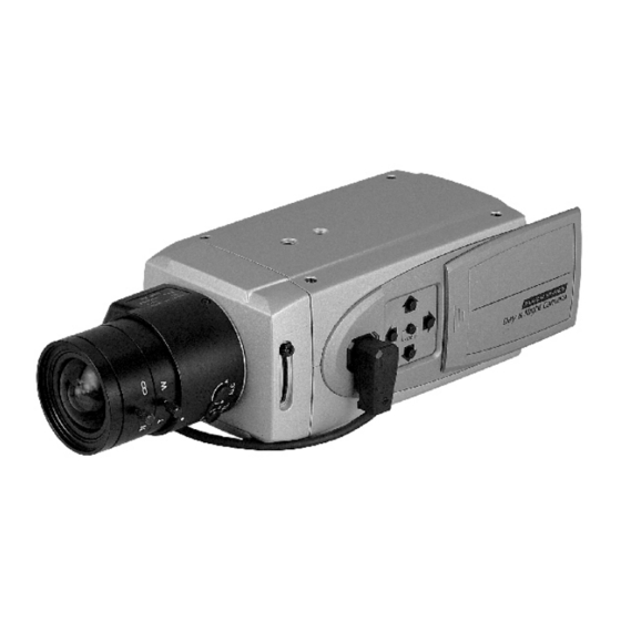
540TV Lines Super High Resolution
Day and Night Color Camera
1/3'' INTERLINE TRANSFER CCD
HIGH RESOLUTION
MANUAL LABEL : 50201270
Please read this manual thoroughly before use, and keep it handy for future reference.
105(+/-5)mm
09.28.M5
09.28.M5
04.26.M6
PRODUCTION RELEASE & REVISION
REV
DESCRIPT'N/BUYER
DWG No
A
INITIAL
BUYER BRAND TYPE
MODEL No.
BRAND
POWER RATING
ADDRESS
81mm
ex) HITRON TYPE
Model No.: HCB-F90N
AC/CA 100-240V ~ 50Hz 5.5W
HITRON SYSTEMS INC.
109-19 MAJEON-RI, SAMJUK-MYEON,
ANSUNG-CITY, KYUNGKI-DO, 456-881 KOREA
NOTES
1.MODEL: HCB-F90N / ALL BRAND
2.MATERIAL: ART PAPER
BIND : STAPLES-2
3.FINISH: -------------
4.COLOR: TEXT-BLACK
5.SIZE: 105(+/-5)mm x 148(+/-5)mm R: 0.0
6.ANY CHANGE OR ALTERNATION MUST BE
APPROVED BY HITRON ENGINEERING.
50301978
UNLESS OTHERWISE SPECIFIED
APPROVALS
ALL DIMENSIONS ARE IN MM.
- TOLERANCE
LABEL
+/- 1.5
MANUAL
+/- 3.5
N.C.PARK
ANGULAR +/- 0.5
MATERIAL
CHKED
2
FINISH
DRAWN
S.A.PARK
PARTS No. BY
CHK
DATE
------------------- 50301978
S.A.P ARK N.C.PARK 09-29-M5
WHITE
ITEM
DESCRIPTION/MATERIAL
QTY
PARTS LIST
DATE
TITLE
04-26-M6
MANUAL INSTRUCTION
-------
SIZE
DWG No
REV.
A4
04-26-M6
P/ N
SCALE
DO NOT SCALE
B
Advertisement
Table of Contents

Subscribe to Our Youtube Channel
Related Manuals for Hitron HCB-F90N


Summary of Contents for Hitron HCB-F90N
- Page 1 HITRON SYSTEMS INC. 109-19 MAJEON-RI, SAMJUK-MYEON, ANSUNG-CITY, KYUNGKI-DO, 456-881 KOREA MANUAL LABEL : 50201270 NOTES 1.MODEL: HCB-F90N / ALL BRAND Please read this manual thoroughly before use, and keep it handy for future reference. 2.MATERIAL: ART PAPER WHITE BIND : STAPLES-2 3.FINISH: -------------...
- Page 2 INSTRUCTION MANUAL 540TV Lines Super High Resolution Day and Night Color Camera 1/3'' INTERLINE TRANSFER CCD HIGH RESOLUTION Please read this manual thoroughly before use, and keep it handy for future reference.
-
Page 4: Limitation Of Liability
LIMITATION OF LIABILITY THE INFORMATION IN THIS PUBLICATION IS BELIEVED TO BE ACCURATE IN ALL RESPECTS, HOWEVER, WE CANNOT ASSUME RESPONSIBILITY FOR ANY CONSEQUENCES RESULTING FROM THE USE THEREOF. THE INFORMATION CONTAINED HEREIN IS SUBJECT TO CHANGE WITHOUT NOTICE. REVISIONS OR NEW EDITIONS TO THIS PUBLICATION MAY BE ISSUED TO INCORPORATE SUCH CHANGES. - Page 5 ISSUE 1 - SEPTEMBER 2005 ISSUE 2 - APRIL 2006 - iv -...
-
Page 6: Warnings And Cautions
WARNINGS AND CAUTIONS: TO REDUCE THE RISK OF FIRE OR ELECTRIC SHOCK, DO NOT EXPOSE THIS PRODUCT TO RAIN OR MOISTURE. DO NOT INSERT ANY MET ALLIC OBJECTS THROUGH THE VENTILATION GRILLS OR OTHER OPENINGS ON THE EQUIPMENT. CAUTION: CAUTION CAUTION RISK OF ELECTRIC SHOCK DO NOT OPEN... -
Page 7: Ce Compliance Statement
CE COMPLIANCE STATEMENT WARNING This is a Class A product. In a domestic environment this product may cause radio interference in which case the user may be required to take adequate measures. - vi -... -
Page 8: Important Safeguards
IMPORTANT SAFEGUARDS 9. CORD AND CABLE PROTECTION 1. READ AND RETAIN INSTRUCTIONS Route power cords and cables in a manner to Read the instruction manual before operating protect them from damage by being walked on the equipment. Retain the manual for future or pinched by items places upon or against reference. - Page 9 17. CAUTION - THESE SERVICING INSTRUCTIONS ARE FOR USE BY QUALIFIED SERVICE PERSONNEL ONLY . TO REDUCE THE RISK OF ELECTRIC SHOCK DO NOT PERFORM ANY SERVICING OTHER THAN THAT CONTAINED IN THE OPERA TING INSTRUCTIONS UNLESS YOU ARE QUALIFIED TO DO SO. - viii -...
-
Page 10: Table Of Contents
TABLE OF CONTENTS INTRODUCTION CAMERA OVERVIEW FUNCTION DESCRIPTION CONTROL AND CONNECTIONS / DAY&NIGHT I/O TERMINALS CONTENTS OF PACKAGE MANUAL IRIS LENS ADJUSTMENT VIDEO AUTO IRIS INSTALLATION & ADJUSTMENT DC AUTO IRIS LENS INSTALLATION & ADJUSTMENT BACK FOCUS ADJUSTMENT ZOOM LENS BACK FOCUS ADJUSTMENT TROUBLESHOOTING AND MAINTENANCE SPECIFICATIONS - ix -... -
Page 11: Introduction
INTRODUCTION The camera provides high-quality images using SONY CCD technology especially designed for closed-circuit television (CCTV) and security surveillance applications. Features: High resolution and high performance 1/3" SONY DSP color Super HAD CCD technology Excellent picture quality 540 lines(Color), 580 lines(B/W) of resolution 0.5 Lux(Color), 0.04 Lux(B/W) @ F1.2 sensitivity C/CS, backfocus cam for easy adjustment Auto electronic shutter [1/50 ~ 1/100,000] and manual electronic shutter... -
Page 12: Camera Overview
CAMERA OVERVIEW SIDE VIEW C Mount Ring ( C MOUNT LENS ) ( CS MOUNT LENS ) TOP & FRONT VIEW IR CUT FILTER - 2 -... -
Page 13: Function Description
FUNCTION DESCRIPTION - SIDE VIEW 1 Focus Adjusting Fixing Screw 2 Auto Iris Lens Connector 3 Left Button 4 Up Button 5 Enter Button 6 Right Button 7 Down Button - REAR VIEW 1 Power Indicator 2 Y/C Output Socket 3 UTP (Unshielded Twisted Pair) Video Output T erminal 4 AC Power Cord 5 RS-485 &... -
Page 14: Cam Set
<MAIN MENU> CAM SET BLC ON D & N SPECIAL PRIVACY DEFAULT SAVE & EXIT EXIT FIGURE 1. MAIN MENU TABLE <CAM SET> Press the MENU button to access the "CAM SET" mode. <CAM SET MENU> CAM ID 1~255 9600 TITLE A B C D E F G H I J K L M N O P Q R S T... - Page 15 <AE> Press the MENU button to access the "AE" mode. <AE MENU> MODE AUTO / SHUTTER / FLICKERLESS SHUTTER ON/OFF LENS -MANUAL LEVEL FLICKERLESS ON/OFF EXIT -VIDEO FLICKERLESS ON/OFF EXIT EXIT FIGURE 3. AE TABLE MODE (This is effective only in case of using manual IRIS LENS) - AUTO Auto Exposure mode (Shutter and AGC) - SHUTTER...
- Page 16 <BLC ON> Press the MENU button to access the "BLC" mode. <BLC MENU> DEFAULT ADJ SIZE ADJ AREA LEVEL(0~50) EXIT FIGURE 4. BLC TABLE DEFAULT Display the sav ed default BLC zone in the monitor. ADJ SIZE Adjust the height and width of the saved default BLC zone. ADJ AREA Move the area of the adjusted BLC zone.
- Page 17 <WB> Press the MENU button to access the "WB" mode. <WB MENU> MODE ATW/AWB/INDOOR/OUTDOOR/MANUAL ON / OFF R GAIN 0 ~ 255 B GAIN 0 ~ 255 EXIT FIGURE 5. WB TABLE MODE - ATW Set the color temperature 2500 K to 9500 K - AWB Auto white balance mode.
- Page 18 <D&N> Press the MENU button to access the "D&N" mode. <D&N MENU> AUTO / COLOR / BW / EXT FILTER DLY 05sec / 10sec / 20sec LEVEL HIGH / NORMAL EXIT FIGURE 6. D&N TABLE - AUTO The COLOR / B/W menu turns the IR(infrared) Filter to on or off.
- Page 19 <SPECIAL> Press the MENU button to access the "SPECIAL" mode. <SPECIAL MENU> CONTOUR HIGH / NORMAL MIRROR ON / OFF NEGA / POSI NEGA / POSI GAMMA ON / OFF SYNC INT / LL PHASE EXIT EXIT FIGURE 7. SPECIAL TABLE CONTOUR Select the sharpness of the picture MIRROR...
- Page 20 <PRIVACY> Press the MENU button to access the "PRIVACY" mode. <PRIVACY MENU> MASK 1 <MASK 1 MENU> DEFAULT ADJ TOP / LEFT ADJ BOT / RIGHT EXIT MASK 2 <MASK 2 MENU> DEFAULT ADJ TOP / LEFT ADJ BOT / RIGHT EXIT MASK 3 <MASK 3 MENU>...
- Page 21 4) OFF The displayed MASK 1 area is disappeared. (MASK 1~ 4) 5) EXIT RETURN to PRIVACY MENU. (MASK 1~ 4) 6) OFF The displayed MASK 1~4 area is disappeared. 7) EXIT RETURN to MAIN MENU. <DEFAULT> Camera initialize mode is selected. (DEFAULT) <SAVE &...
-
Page 22: Control And Connections / Day&Night I/O Terminals
CONTROL AND CONNECTIONS /DAY& NIGHT I/O TERMINALS RS-485 485-(TX) 485+(RX) 1) CAMERA CONTROL 1 PIN : RS 485- 2 PIN : RS 485+ 2) DAY&NIGHT I/O Terminals To select Day/Night mode using external equipment, connect control lines to the appropriate terminals. 3 PIN : Control OUT Regardless of the D/N mode, it is provided 0V at Color mode, and 5V at B/W mode. - Page 23 4) VIDEO OUT CONNECTOR BNC : This BNC connector provides a 1.0Vp-p/75 ohms composite video signal. Y/C : Y (1.0Vp-p) and C (0.3Vp-p) signals are provided at this connector. Y/C socket GND Y GND C UTP : Unshielded Twisted Pair video Transmission for effective installation. - 13 -...
-
Page 24: Contents Of Package
CONTENTS OF PACKAGE Installation of the camera must be performed by qualified service personnel in accordance with all local and national electrical and mechanical codes. Carefully remove the color camera and its accessories from the carton and verify that they were not damaged in shipment. The contents of the package includes: Color CCD camera Mini-DIN connector (for video-or dc-type auto-iris lens) -
Page 25: Video Auto Iris Installation & Adjustment
VIDEO AUTO IRIS INSTALLATION & ADJUSTMENT The camera supports video-type auto iris lenses which adjust to changing light levels. Perform the following steps to install and adjust a video-type auto iris lens. If necessary, solder the lens control wires to the connector supplied with the camera. -
Page 26: Dc Auto Iris Lens Installation & Adjustment
For ALC adjustments: To slow the reaction of the lens to changing light, set the range to the AVG setting to average the video level from the camera. Use when there are bright spots in the picture such as lights or glare from the sun. - Page 27 NAME WIRE COLOR Damp Coil - Blue Damp Coil + Drive Coil + White Drive Coil - Green Attach the DC-type auto iris lens to the lens mount on the front of the camera. Plug the connector into the auto iris jack on the back of the camera. The connector is polarized and can only be inserted into the jack one way.
-
Page 28: Back Focus Adjustment
BACK FOCUS ADJUSTMENT For best results, perform back focus adjustments at night or while using a #6 or #8 welder's glass in front of the lens. The focus of the camera will change slightly if the camera iris was adjusted on a light scene, then changes to a dark scene. -
Page 29: Zoom Lens Back Focus Adjustment
ZOOM LENS BACK FOCUS ADJUSTMENT The objective of back focusing a zoom lens is similar to that of a fixed focal length camera except the back focus is also adjusted to maintain the focus when "zooming" the lens in and out on a scene. Choose an object at the farthest range set for viewing with a zoom lens. -
Page 30: Troubleshooting And Maintenance
TROUBLESHOOTING AND MAINTENANCE TROUBLESHOOTING If problems occur, verify the installation of the camera with the instructions in this manual and with other operating equipment. Isolate the problem to the specific piece of equipment in the system and refer to the equipment manual for further information. PROBLEM AREA TO CHECK No video... -
Page 31: Specifications
SPECIFICATIONS Super High Resolution Day&Night Color Camera Power source 100-240V ~ 50Hz +/- 1Hz Power Power consumption 5.5 Watts Image sensor 1/3" Super-HAD Color CCD (SONY) Total number of pixels 795(H) x 596(V) Unit cell size Scanning system 2:1 interlace General Scanning frequency 15.625KHz(H) x 50Hz(V) - Page 33 540TV Lines Super High Resolution Day and Night Color Camera 50301978B PRINTED IN KOREA...
Need help?
Do you have a question about the HCB-F90N and is the answer not in the manual?
Questions and answers