Table of Contents
Advertisement
Manual Label Name
(50201073: 120x30mm)
CS
06.30.M5
04.25.M5
215(+/-5)mm
PRODUCTION RELEASE & REVISION
REV
DWG No
DESCRIPT'N/BUYER
A
INITIAL / ALL BRAND
------------------ 50301755 Y.Y .KIM
BUYER BRAND TYPE (LABEL : 50201073)
MODEL No.:
POWER
BRAND
ADDRESS
120mm
ex) HITRON TYPE
HID2404SLE11N
Model No.:
AC/CA 24V ~ 60Hz MAX. 20W
DC 24V
MAX. 20W
HITRON SYSTEMS INC.
109-19 MAJEON-RI, SAMJUK-MYEON,
ANSUNG-CITY, KYUNGKI-DO, 456-881 KOREA
NOTES
1.MODEL: HID2404SME11N/P , HID2404SHE11N/P ,
HID2404SLE11N/P , HID2404HTE11N/P ,
HID2404SSE11N/P - ALL BRAND
BIND : STAPLES-2
3.FINISH: -------------------
4.COLOR: TEXT-BLACK
5.SIZE: 215(+/-5)mm x 280(+/-5)mm R: 0.0
6.ANY CHANGE OR ALTERNATION MUST BE
APPROVED BY HITRON ENGINEERING.
50301755
ITEM
APPROVALS
UNLESS OTHERWISE SPECIFIED
ALL DIMENSIONS ARE IN MM.
- TOLERANCE
LABEL
+/- 1.5
MANUAL
+/- 3.5
07-01-M5
N.C.PARK
ANGULAR +/- 0.5
MATERIAL
CHKED
2
FINISH
DRAWN
S.A.PARK
07-01-M5
PARTS No.
BY
DATE
CHK
N.C.PARK 07-09-M4
DESCRIPTION/MATERIAL
QTY
PARTS LIST
DATE
TITLE
MANUAL INSTRUCTION
SIZE
DWG No
REV.
G
A4
P/ N
SCALE
--------------
DO NOT SCALE
Advertisement
Table of Contents

Related Manuals for Hitron FASTRAX II E


Summary of Contents for Hitron FASTRAX II E
- Page 1 HID2404SLE11N/P , HID2404HTE11N/P , HID2404SSE11N/P - ALL BRAND BIND : STAPLES-2 3.FINISH: ------------------- 4.COLOR: TEXT-BLACK 5.SIZE: 215(+/-5)mm x 280(+/-5)mm R: 0.0 6.ANY CHANGE OR ALTERNATION MUST BE 215(+/-5)mm APPROVED BY HITRON ENGINEERING. 50301755 ITEM DESCRIPTION/MATERIAL PARTS LIST APPROVALS DATE UNLESS OTHERWISE SPECIFIED ALL DIMENSIONS ARE IN MM.
- Page 2 FASTRAX ll E DOME CAMERA Instruction Manual Please read this manual thoroughly before use and keep it handy for future reference. Rev.050701...
- Page 3 Warnings and Cautions WARNING TO REDUCE THE RISK OF FIRE OR ELECTRIC SHOCK, DO NOT EXPOSE THIS PRODUCT TO RAIN OR MOISTURE. DO NOT INSERT ANY METALLIC OBJECTS THROUGH THE VENTILATION GRILLS OR OTHER OPENINGS ON THE EQUIPMENT. CAUTION EXPLANATION OF GRAPHICAL SYMBOLS The lightning flash with arrowhead symbol, within an equilateral triangle, is intended to alert the user to the presence of uninsulated "dangerous voltage"...
- Page 4 FCC COMPLIANCE STATEMENT FCC INFORMATION: THIS EQUIPMENT HAS BEEN TESTED AND FOUND TO COMPLY WITH THE LIMITS FOR A CLASS A DIGITAL DEVICE, PURSUANT TO PART 15 OF THE FCC RULES. THESE LIMITS ARE DESIGNED TO PROVIDE REASONABLE PROTECTION AGAINST HARMFUL INTERFERENCE WHEN THE EQUIPMENT IS OPERATED IN A COMMERCIAL ENVIRONMENT.
- Page 5 IMPORTANT SAFEGUARDS 1. Read these instructions. 2. Keep these instructions. 3. Heed all warnings. 4. Follow all instructions. 5. Do not use this apparatus near water. 6. Clean only with dry cloth. 7. Do not block any ventilation openings. Install in accordance with the manufacturer's instructions.
-
Page 6: Table Of Contents
1.1 Features...............................1 Chapter 2 — Installation and Configuration ................3 2.1 Package Contents..........................3 2.2 Basic Configuration of Fastrax II E Dome Camera System..............4 2.3 Setting Dome Camera Termination......................5 2.4 Setting Dome Camera Address (ID) ....................7 2.5 Setting Dome Camera Protocol ......................8 2.6 Connections ............................9... - Page 7 3.13 Camera – HID2404HCExxx MODEL.................... 24 Focus Control ..........................24 WB (White Balance) Control ....................... 24 AE Control ..........................25 Line Lock Cont rol ........................26 Night Shot Menu ........................26 3.14 Camera – HID2404HTExxx MODEL.................... 27 Focus Control ........
-
Page 8: Chapter 1 - Introduction
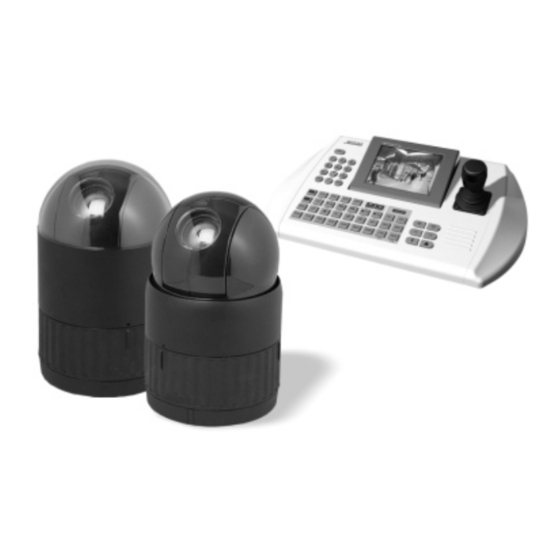
Chapter 1 — Introduction 1.1 Features The Fastrax II E dome camera and the Fastrax II Keyboard Controller make up the building blocks for any surveillance/security system. Using multiple Keyboard Controllers and multiple dome cameras, no place is too large for monitoring. Extensible and flexible architecture facilitates remote control functions for a variety of external switching devices such as multiplexers and DVRs. - Page 9 UP TO 255 MULTIPLEXER Alarm Input UP TO 8 <Sensor> UP TO 99 DVR <Siren> Alarm Output UP TO 4 <Flashing Light> UP TO 32 CAMERA J-box Master Keyboard Figure 1 – Typical System Configuration push bubble ring ass'y remove camera window screw push remove window...
-
Page 10: Chapter 2 - Installation And Configuration
2.1 Package Contents The package contains the following. Fastrax II E (Dome Camera) ………………………1 Bubble Ring ………………………1 Instruction Manual (This Document) ………………………1 Assembly Screws for Attaching Fastrax II E ………………………3 Plastic Anchor ………………………3 10Pin Connector ………………………1 12Pin Connector ………………………2 CAUTION: Be sure to have caution labels ( version only) on both the body and the base of the camera. -
Page 11: Basic Configuration Of Fastrax Ii E Dome Camera System
2.2 Basic Configuration of Fastrax II E Dome Camera System. J-BOX DOME POWER RS485(+) DOME1 + RX+(TX+) AC 24V RS485(-) DOME1 - RX-(TX-) STP AWG # 22 ALARM OUTPUT ALARM INPUT POWER AC 24V SENSOR ALARM INPUT UP TO 8... -
Page 12: Setting Dome Camera Termination
The dome camera must be installed by qualified service personnel in accordance with all local and federal electrical and building codes. The system should be installed according to Figures 4 through 9. Termination Switches KSD02H Address(ID) and Protocol selection Switches Figure 5 –... - Page 13 Figure 7- Termination Diagram...
-
Page 14: Setting Dome Camera Address (Id)
2.4 Setting Dome Camera Address (ID) To prevent damage, each dome camera must have a unique address (ID). When installing multiple dome cameras using a multiplexer, it is suggested that the dome camera address match the multiplexer port number. If you want to set the address more than 999, you should contact the service provider. Example: Port 1 = Dome 1, Port 2 = Dome 2 …... -
Page 15: Setting Dome Camera Protocol
2.5 Setting Dome Camera Protocol If a dome camera is to be installed with a Fastrax keyboard controller, select F2 protocol. Consult service personnel if a dome camera is installed with device other than a keyboard controller. UNCTION NTSC S4-1 Enable Disable Alarm... -
Page 16: Connections
2.6 Connections • Connecting to the RS485/ 422 The dome camera can be controlled remotely by an external device or control system, such as a control keyboard, using RS485 half-duplex, RS422 duplex or simplex serial communications signals. Connect Marked Rx+, Rx- to Tx+ and Tx- of the RS485 control system. If control system is RS422, connect Rx+(Tx+), Rx+(Tx-) and Rx+, Rx- of the dome camera to Tx+, Tx- and Rx+, Rx- of the control device respectively. - Page 17 RAM TEST CHECK NO. : OK! CHECK AAAA : OK! CHECK 5555 : OK! FASTRAX II E Vx.xxx CAMERA TYPE xxxx WAIT DOME SETTING. INIT TILT ORGIN SET OK INIT PAN ORGIN SET OK INIT CAMERA SET OK PRESET No.
-
Page 18: Chapter 3 - Program And Operation
Chapter 3 — Program and Operation 3.1 Dome Camera Selection Before you program or operate a dome camera, you must select the dome camera by pressing the dome camera No. + CAM Example: Pressing 1 , 0 and CAM key sequentially will select dome camera 10. The selected dome camera ID will be displayed on the LCD monitor of the keyboard controller. -
Page 19: How To Control On-Screen Menu Utility
3.3 How to control the On-Screen Menu Utility Action Function Call the On-screen menu utility MENU Go into the sub-menu items. Execute the command(exit) Joystick left or right Change value. Navigate through the menu items. Navigate through the menu items. Joystick up or down Finish editing title. - Page 20 1. Press the SCAN key to enter Auto Scan menu directly. Or press the MENU key to display the main menu on the monitor. Scroll to Auto Scan and push the Joystick to the right. 2. Select an Auto Scan number by pushing the Joystick left or right. 3.
-
Page 21: Preset
Also you can execute Endless Auto Scan which is to turn one direction continuously by Pressing 9 + SCAN. 3.5 Preset (Second Item of the Main menu / Shortcut: PRST) If you need to view specific places routinely, you should program presets. A preset is a programmed video scene with automatic pan, tilt, zoom, focus and iris settings. -
Page 22: Shortcut Preset Program
5. After aiming the camera (view direction and lens control), release CTRL/PGM. Then twist the Joystick handle or Press Tele or Wide Key to store the selected view. The position number will be displayed and the user will be prompted to enter a preset title. 6. - Page 23 Tour2 executes as follows: Preset3 Preset4 Preset7 Preset5 Preset1 … Repeat (Tour4 is still valid if called directly from Tour2.) TOUR 01:xxxxxxxxxxxxxxxx SCAN TYPE:NORMAL === === 003 === === === === A08 === === === === === === === T02 === 001 === === === === === === T08 === === === === === === === === === === === === === === === === ===...
-
Page 24: Pattern
through the alphanumeric characters. Push the handle to the right or left to select the next or previous digit. 9. Select Save and Exit by pushing the Joystick to the right. Press ESC to exit the program without saving. NOTE: Press the Home key at a programmed position to delete programmed function. In the Tour mode, in conjunction with preset and Auto Scan, you can make the camera travel from a preset position to another preset position at a specific speed. -
Page 25: Alarm
7. Pressing ESC will not save your information and exits to the previous mode. Press the HOME key at any programmed position to delete that programmed pattern. NOTE: If total recording time reaches 240 seconds, it will automatically stop for a moment and restart recording. -
Page 26: Area Title
3.10 Area Title (Sixth Item of Main menu) Enter a specific name on programmed angle between START and END. For the screen below, when the camera points at an angle between 124.3° to 359.5°, ABC will be displayed on the screen. -
Page 27: Privacy Zone
3.11 Privacy Zone (Seventh Item of Main menu) Hide up to 8 unwanted views in a camera. PRIVACY ZONE SETUP TITLE METHOD 01 xxxxxxxxxxxxxxxx BLOCK 02 xxxxxxxxxxxxxxxx V.OFF 03 xxxxxxxxxxxxxxxx NONE ==== 04 xxxxxxxxxxxxxxxx NONE ==== 05 xxxxxxxxxxxxxxxx NONE ==== 06 xxxxxxxxxxxxxxxx NONE ==== 07 xxxxxxxxxxxxxxxx... -
Page 28: Camera -Hid2404Sxexxx Model
3.12 Camera (Eighth Item of Main menu) – HID2404SxExxx MODEL NOTE: The menu features will vary depending on the camera module installed in your dome camera. CAMERA SETUP FOCUS CONTROL WB CONTROL AE CONTROL LINE LOCK CONTROL SHARPNESS BACK LIGHT : OFF DIGITAL ZOOM : OFF (2X/4X/MAX) -
Page 29: Wb (White Balance) Control
• WB (White Balance) CONTROL WB SETUP MODE AUTO R GAIN : B GAIN : EXIT(ESC TO EXIT) MODE MANUAL / AUTO / INDOOR / OUTDOOR / ONE PUSH / ATW RGAIN 0 ~ 255 BGAIN 0 ~ 255 Use the ATW mode for normal use. RGAIN / BGAIN modes are controllable only in MANUAL Mode Push the Joystick to the right or left to change. -
Page 30: Line Lock Control
• LINE LOCK CONTROL LINE LOCK SETUP MODE INTERNAL PHASE EXIT(ESC TO EXIT) MODE INTERNAL / EXTERNAL Adjusts phase of picture with other PHASE 0~255 cameras in EXTERNAL mode. EXIT (ESC TO EXIT) • NIGHT SHOT MENU The NIGHT SHOT option removes the IR cutoff filter of the camera and makes the camera sensitive to near infrared. -
Page 31: Camera - Hid2404Hcexxx Model
3.13 Camera (Eighth Item of Main menu) – HID2404HCExxx MODEL NOTE: The menu features will vary depending on the camera module installed in your dome camera. CAMERA SETUP FOCUS CONTROL WB CONTROL AE CONTROL LINE LOCK CONTROL SHARPNESS : 32 BACK LIGHT : OFF DIGITAL ZOOM... -
Page 32: Wb (White Balance) Control
• WB (White Balance) CONTROL WB SETUP MODE AUTO R GAIN : B GAIN : EXIT(ESC TO EXIT) MODE MANUAL / AUTO RGAIN 0 ~ 255 BGAIN 0 ~ 255 Use the AUTO mode for normal use. RGAIN / BGAIN modes are controllable only in MANUAL Mode Push the Joystick to the right or left to change. -
Page 33: Line Lock Control
• LINE LOCK CONTROL LINE LOCK SETUP MODE INTERNAL PHASE : EXIT(ESC TO EXIT) MODE INTERNAL / EXTERNAL Adjusts phase of picture with other PHASE 0~255 cameras in EXTERNAL mode. EXIT (ESC TO EXIT) • NIGHT SHOT MENU The NIGHT SHOT option removes the IR cutoff filter of the camera and makes the camera sensitive to near infrared. -
Page 34: Camera - Hid2404Htexxx Model
3.14 Camera (Eighth Item of Main menu) – HID2404HTExxx MODEL NOTE: The menu features will vary depending on the camera module installed in your dome camera. CAMERA SETUP FOCUS CONTROL WB CONTROL AE CONTROL LINE LOCK CONTROL SHARPNESS : 10 BACK LIGHT : OFF DIGITAL ZOOM... -
Page 35: Wb (White Balance) Control
• WB (White Balance) CONTROL WB SETUP MODE R GAIN : B GAIN : EXIT(ESC TO EXIT) MODE AWB / WAWB / INDOOR / DOUDOOR / MANUAL WAWB Wide range auto white balance mode. RGAIN 0 ~ 255 BGAIN 0 ~ 255 Use the AWB mode for normal use. -
Page 36: Line Lock Control
• LINE LOCK CONTROL LINE LOCK SETUP MODE INTERNAL PHASE : EXIT(ESC TO EXIT) MODE INTERNAL / EXTERNAL Adjusts phase of picture with other PHASE 0~255 cameras in EXTERNAL mode. EXIT (ESC TO EXIT) 3.15 Camera – HID2404SSExxx MODEL (Eighth Item of Main menu) Eclipse of the Lens: The eclipse phenomenon occurs with this model. -
Page 37: Dome Setup
3.15 Dome Setup (Ninth Item of Main menu) CONFIGURATION MENU HOME FUNCTION SETUP OSD DISPLAY VIEW ANGLE SETUP INITIALIZE DATA ORIGIN OFFSET DOME RESET SYSTEM INFORMATION EXIT(ESC TO EXIT) • HOME FUNCTION SETUP After a dome control menu item has been selected, follow the directions below to set the function. HOME FUNCTION SETUP HOME FUNCTION : NONE... -
Page 38: Osd Display
• OSD DISPLAY DISPLAY SETUP CAMERA TITLE : DOMEID VIEW DIRECTION : OFF DOME OSD DISPLAY : ON AREA DISPLAY : OFF SAVE AND EXIT(ESC TO CANCEL) CAMERA TITLE : 8 CHARACTER CAN BE SET VIEW DIRECTION : ON / OFF DOME OSD DISPLAY : ON / OFF AREA DISPLAY... -
Page 39: Panning Range
• PANNING RANGE When the dome camera is installed near a wall, panning range can be limited by user. PANNING RANGE SETUP RIGHT LIMIT : 000.0 LEFT LIMIT : 000.0 ENABLE : OFF SWAP RIGHT/LEFT SAVE AND EXIT(ESC TO CANCEL) •... -
Page 40: Origin Offset
Erase all stored data from the Flash-ROM of the selected dome camera. You will be asked to enter Yes or No. If you intend to erase all data then press the MENU key, otherwise press the ESC key to exit without erasing. The erased data includes all stored data (titles, presets, and tours….) except origin offset. -
Page 41: Appendix A - Specifications
Appendix A — Specifications Camera (HID2404SLExxx) Image Sensor 1/4" Super HAD Color CCD (Sony) NTSC : 768 x 494 Approx. 380K pixels Picture elements : 752 x 582 Approx. 440K pixels Horizontal Resolution 480 / 470 lines (NTSC / PAL) 18x optical zoom with auto focus Lens 12x digital zoom... - Page 42 Camera (HID2404HCExxx) Image Sensor 1/4" Progressive scan CCD NTSC : 758 x 504 Approx. 380K pixels Picture elements : 758 x 592 Approx. 450K pixels Horizontal Resolution 480 / 470 lines (NTSC / PAL) 23x optical zoom with auto focus Lens 10x digital zoom F1.6 to F3.6, f=3.6mm to 82.8mm...
- Page 43 General Certification CE EMC, FCC CLASS A, CSA Electrical Input Voltage 18 to 30VAC; 24VAC nominal, 24VDC, built-in power-line surge Power Requirement 24VAC/VDC 1A Power Consumption Maximum 20W Alarm Output 4 Normal relays 24 VDC/1A Max. (selectable NC/NO) Alarm Input 8 Normal dry contact (selectable NC/NO) Control RS-485/422 baud rate: 2400~230k bps (default: 9600bps)
-
Page 44: Appendix B - Troubleshooting
Appendix B — Troubleshooting If problems occur, verify the installation of the camera with the instructions in this manual and with other operating equipment. Isolate the problem to the specific piece of equipment in the system and refer to the equipment manual for further information. Problem Possible Solution Verify that power is connected to all pieces of... -
Page 45: Appendix C - Glossary
Appendix C — Glossary Alarm Actions The assigned responses for the dome camera when inputs change from normal to abnormal states. The dome may run a Preset, Pattern, or have no assigned action for each of the four dome inputs. The dome may also send alarm states to the host controller for processing. See also Input and Normal Input State. - Page 46 IR Mode A feature of the camera that permits manual or automatic switching between color and IR (black-and-white) operation. When IR mode is active, clearer images may be obtained under low-light conditions. Line Lock Allows you to phase lock the video with the AC power line. When line lock is enabled, it prevents vertical video rolling when switching multiple cameras to a single monitor.
- Page 47 Privacy Zones Masked areas of the dome camera's viewing area. These masks prevent operators of the surveillance system from viewing these designated zones. The Privacy Zones move in relation to the dome camera’s pan/tilt position. In addition, the apparent size of the Privacy Zone adjusts automatically as the lens zooms in or out.
-
Page 48: Appendix D - Short Cut Key
Appendix D — Short Cut Key Short Cut Key Function Pop up preset setup menu. PRST Pop up guard Tour setup menu. TOUR Pop up Pattern setup menu. PTRN Pop up Auto Scan setup menu. SCAN NO.+ PGM +PRST Store the current view at the selected number. Pop up tour setup menu at the selected number. - Page 49 FASTRAX ll E DOME CAMERA 50301755G Printed in Korea...
Need help?
Do you have a question about the FASTRAX II E and is the answer not in the manual?
Questions and answers