Table of Contents
Advertisement
Quick Links
Advertisement
Table of Contents

Related Manuals for FUTABA 14SG S.Bus2

Summary of Contents for FUTABA 14SG S.Bus2
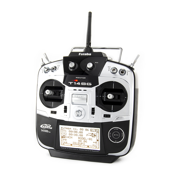
- Page 1 14 CHANNEL COMPUTER SYSTEM 1M23N27902...
-
Page 2: Table Of Contents
TABLE OF CONTENTS INTRODUCTION..........4 Low battery alarm and auto shut-down ..34 Warning display at power on ......34 ●Support and Service ......... 4 ●Registration of the user's name ..... 34 ●Application, Export, and Modification ... 5 ●Home screen ............ 35 ●Definitions of Symbols ........ - Page 3 Throttle Cut (Air/Heli only) ......83 Camber Mix (Except 1-AIL) ....... 127 Idle Down (Air only) ........84 ELE to Camber (Except 1-AIL) ....129 Swash Ring (Heli only) ........85 Camber FLP to ELE (2-AIL+1-FLP and up) 130 Swash (Heli only, except H-1) ......86 Butterfly (Glid only, normal wing 2-AIL and up, flying wing 2-AIL+1FLP and up) ..
-
Page 4: Introduction
Email: service@futaba-rc.com OUTSIDE NORTH AMERICA Please contact your Futaba importer in your region of the world to assist you with any questions, problems or service needs. Please recognize that all information in this manual, and all support availability, is based upon the systems sold in North America only. -
Page 5: Application, Export, And Modification
Any such changes may void the warranty. Compliance Information Statement (for U.S.A.) This device, trade name Futaba Corporation of America, model number R7008SB, complies with part 15 of the FCC Rules. Operation is subject to the following two conditions:... -
Page 6: Definitions Of Symbols
EEPROM memory (which does not require periodic replacement) and not a battery, the transmitter still should have regular checkups for wear and tear. We recommend sending your system to the Futaba Service Center annually during your non-flying-season for a complete checkup and service. - Page 7 NiMH/NiCd Battery Charge the batteries! (See Charging the NiCd batteries, for details.) Always recharge the transmitter and receiver batteries before each flying session. A low battery will soon die potentially, causing loss of control and a crash. When you begin your flying session, reset your T14SG’s built-in timer, and during the session pay attention to the duration of usage.
- Page 8 NiMH/NiCd Battery Safety and Handling instructions IMPORTANT! Use only the Futaba special charger included with this set or other chargers approved by Futaba to charge the NiMH batteries in the T14SG transmitter included with this set. It is important to understand the operating characteristics of NiMH/NiCd batteries.Always read the specifications printed on the label of your NiMH/NiCd battery and charger prior to use.
- Page 9 At the flying field To prevent possible damage to your radio gear, turn the power switches on and off in the proper sequence: 1. Pull throttle stick to idle position, or otherwise disarm your motor/engine. 2. Turn on the transmitter power and allow your transmitter to reach its home screen. 3.
-
Page 10: Before Use
BEFORE USE Features FASSTest system The T14SG transmitter has adopted the newly developed bidirectional communication system "FASSTest" . Data from the receiver can be checked in your transmitter. FASSTest is a maximum 14 channels (linear 12 channels + switch 2 channels) 2.4GHz dedicated system. S.BUS2 system By using the S.BUS2 system multiple servos, gyros and telemetry sensors are easily installed with a minimum amount of cables. -
Page 11: Contents And Technical Specifications
Contents and Technical Specifications (Specifications and ratings are subject to change without notice.) Your 14SG includes the following components: • T14SG transmitter for airplanes or helicopters • R7008SB Receiver • HT5F1800B NiMH battery & Charger • Li-Fe spacer for optional FT2F2100B/FT2F1700B LiFe battery pack. •... -
Page 12: Accessories
TRAINER function instructions). The part number of this cord is: FUTM4405. • Servos - there are various kinds of servos. Please choose from the servos of Futaba what suited the model and the purpose of using you. If you utilize a S.BUS system, you should choose a S.BUS servo. An analog servo cannot be used if "FASSTest12CH mode"... -
Page 13: Transmitter Controls
Transmitter controls Antenna Monitor LED Volume Switch Switch Slide Lever Slide Lever Stick Stick (J3) (J2) (J4) (J1) HOME/EXIT U.MENU/MON. Button Button Digital Trim Digital Trim SensorTouch Neck Strap Attachment Power Switch <Before Use>... -
Page 14: Cautions On Handling Antenna
Caution Transmitter's Antenna: As with all radio frequency transmissions, the Please do not grasp the transmitter's strongest area of signal transmission is from the antenna during flight. sides of the transmitter's antenna. As such, the D o i n g s o m a y d e g r a d e t h e q u a l i t y o f t h e R F antenna should not be pointed directly at the model. -
Page 15: Switch (Sa-Sh)
Switch (SA-SH) Slide Lever (Switch Type) • SA : 3 positions; Alternate; Short lever • SB : 3 positions; Alternate; Long lever • SC : 3 positions; Alternate; Long lever • SD : 3 positions; Alternate; Short lever • SE : 3 positions;... -
Page 16: Touch Sensor
Touch sensor operation Data input operation is performed using the touch sensor. SensorTouch™ operation Condition Working • Short 'tap' If the screen has more than one page. (Ex. P-MIX screen) The cursor moves to the top of next page. If the screen have only one (1) page. The cursor moves to the top of page. -
Page 17: Stick Adjustment
Note: 1. Hold the lever head "B" and turn the lever head "A" counter-clockwise. The lock will be *Scroll operation: Circle your finger on the outside edge of released. the RTN button. The sensors may mis-read your touch as a 2. - Page 18 4. Use a small Phillips screwdriver to adjust the spring strength as you prefer by turning the adjusting screw of the stick you want to adjust. *Turning the screw clockwise increases the tension. CAUTION: If you loosen the screw too much, it can interfere with the operation of the sticks internally.
-
Page 19: Sd Card
*An SD card formatted to the T14SG cannot be written below. directly from a PC by Windows Explorer, etc. The files must be converted and written by the Futaba File System software. Files are identified by number instead of name. This special conversion software can be downloaded from Futaba's web site at: http://www.futaba-rc.com/software-updates.html... - Page 20 Saving model data and update files (released To use an SD card with the T14SG, the card from Futaba) to the SD card from your own must first be formatted. Once formatted, the card PC, you can transfer those file to your T14SG does not have to be reformatted.
-
Page 21: Connector/Plug
Connector/Plug Trainer Connector S.BUS (S.I/F) Connector Charge Plug Earphone Plug Connector for trainer function Connector for battery charger When you use the trainer function, connect the optional trainer cable between the transmitters for This is the connector for charging the NiMH teacher and student. -
Page 22: Installation And Removal Of The Battery
Do not use the transmitter as it is. Send it to the Futaba Service Center. 2. Install the battery in the holder. 3. Connect the battery connector. - Page 23 When exchanging for the LiFe battery (FT2F2100B/FT2F1700B) of an option. Attachment of the battery 1. T14SG to HT5F1800B is removed. 2. A LiFe spacer (14SG attachment) is inserted as shown in a figure. Charge of a LiFe battery 3. A LiFe battery (option) is inserted as shown in Note: LiFe battery cannot be charged with the a figure.
-
Page 24: Receiver Nomenclature
Receiver nomenclature Danger Before using the receiver, be sure to read the Don't connect a connector, as shown in a precautions listed in the following pages. before figure. Receiver R7008SB *It will short-circuit, if it connected in this way. A short circuit across the battery terminals may cause abnormal heating, fire and burns. - Page 25 Danger Don't touch wiring. * There is a danger of receiving an electric shock. Do not short-circuit the battery terminals. * A short circuit across the battery terminals may cause abnormal heating, fire and burns. Please double check your polarity ( + and -...
-
Page 26: Receiver's Antenna Installation
Receiver's Antenna Installation The R7008SB has two antennas. In order to maximize signal reception and promote safe modeling Futaba has adopted a diversity antenna system. This allows the receiver to obtain RF signals on both antennas and fly problem-free. *Must be kept as straight as possible. -
Page 27: Safety Precautions When Installing Servos
Safety precautions when you install Mounting the Servo receiver and servos Wood screw 2.3-2.6mm nut Warning washer Rubber Rubber grommet grommet Connecting connectors Brass eyelet Brass eyelet Servo mount Servo mount Be sure to insert the connector until it stops 2.3-2.6mm screw at the deepest point. -
Page 28: S.bus/S.bus2 Installation
S.BUS/S.BUS2 Installation This set uses the S.BUS/S.BUS2 system. The wiring is as simplified and clean mounting as possible, even with models that use a large number of servos. In addition, the wings can be quickly installed to the fuselage without any erroneous wiring by the use of only one simple wire, even when there are a large number of servos used. -
Page 29: S.bus Wiring Example
S.BUS Wiring example *When using 8/SB as S.BUS, you must set the receiver to Mode B or Mode D. See Mode Chart page 25. Since the channel number is memorized by Battery the S.BUS itself, any connector can be used. S.BUS Port When the SBD-1 (sold separately) is used,... -
Page 30: S.bus2 System
S.BUS2 System When using the S.BUS2 port, an impressive array of telemetry sensors may be utilized. S.BUS2 TABLE S.BUS2 S.BUS Servo Servo Receiver port Telemetry sensor S.BUS2 S.BUS Gyro Gyro S.BUS ○ ○ × S.BUS2 × (※) ○ ○ (※)Don't connect S.BUS Servo, S.BUS Gyro to S.BUS2 connector. -
Page 31: S.bus/S.bus2 Devicesetting
S.BUS/S.BUS2 device setting S.BUS/S.BUS2 servos or a telemetry sensor can be connected directly to the T14SG. Channel setting and other data can be entered for the S.BUS/S.BUS2 servos or sensors. 1. Connect the S.BUS device and battery you want to set with a 3-way hub or Y-harnesses as shown in the figure. -
Page 32: Telemetry System
Telemetry System The R7008SB receiver features bi-directional communication with a FASSTest Futaba transmitter using the S.BUS2 port. Using the S.BUS2 port an impressive array of telemetry sensors may be utilized. It also includes both standard PWM output ports and S.BUS output ports. -
Page 33: Basic Operation
BASIC OPERATION Battery Charging Before charging batteries, read the "Cautions for handling battery and battery charger" in the section "NiMH/NiCd Battery Safety and Handling Instructions". How to charge the NiMH battery HT5F1800B *Battery charging will not automatically stop. Remove the battery and transmitter from the charger and remove the for the transmitter charger from the wall socket. -
Page 34: How To Turn On/Off The Transmitter
How to turn transmitter power ON/OFF Registration of the user's name When turning on the power, the T14SG If so desired, the T14SG transmitter can transmitter will begin emmiting RF automatically indicate the owner's name. after it confirms the surrounding RF conditions. User's name setup screen The T14SG transmitter also offers the ability to 1. -
Page 35: Home Screen
Home screen Use the touch sensor to select the following display area to call each setting screen, and touch the RTN button. The setting screen appears. System timer Key lock • This shows the accumulated time since • Touch the S1 button or push the the latest reset. (Hour):(Minute) HOME/EXIT button for one second to lock/unlock the key operation. -
Page 36: User Menu
User Menu Warning A user menu which allows the user to customize Be sure to confirm the model name before and display frequently used functions has been flying your aircraft. added. 1. When the "U.MENU" button is pushed for two Check the battery voltage as often as possible seconds, the user menu appears. -
Page 37: Link Procedure (T14Sg/R7008Sb)
Link procedure (T14SG/R7008SB) Each transmitter has an individually assigned, unique ID code. In order to start operation, the receiver must be linked with the ID code of the transmitter with which it is being paired. Once the link is made, the ID code is stored in the receiver and no further linking is necessary unless the receiver is to be used with another transmitter. - Page 38 11. When a telemetry function is enabled, the receiving interval (down-link interval) of sensor data can be changed. If a DL interval is increased, the response of the sensor data display becomes slower, but stick response will improve. Initial value: 1.0s Adjustment range: 0.1s~2.0s * If there are many FASSTest systems turned on around your receiver, it might not link to your transmitter.
-
Page 39: Range Testing Your R/C System
Range Testing Your R/C System It is extremely important to range check your models prior to each flying session. This enables you to ensure that everything is functioning as it should and to obtain maximum enjoyment from your time flying. The T14SG transmitter incorporates a system that reduces its power output and allows you to perform such a range check. -
Page 40: Raceiver And Servo Installation
RECEIVER AND SERVO INSTALLATION Receiver and servos connection Connect the receiver and servos in accordance with the connection diagram shown below. Always read the section [Before using]. When mounting the receiver and servos to the fuselage, connect the necessary points in accordance with the model's instruction manual. Receiver and servos connection diagram Always connect the necessary number of servos. -
Page 41: Servo Connection By Model Type
Servo connection by model type The T14SG transmitter channels are automatically assigned for optimal combination according to the type selected with the Model Type function of the Linkage Menu. The channel assignment (initial setting) for each model type is shown below. Connect the receiver and servos to match the type used. *The set channels can be checked at the Function screen of the Linkage Menu. - Page 42 Airplane/glider Flying wing, Delta wing R X 2Aileron 2Aileron+1FLAP 2Aileron+2FLAP 2Aileron+4FLAP 4Aileron+2FLAP Airplane Glider Airplane Glider Airplane Glider Airplane Glider Airplane Glider Aileron Aileron Aileron Aileron Aileron Aileron Aileron Aileron Aileron Aileron AUX4 AUX4 AUX4 Aileron2 Aileron2 Aileron2 Aileron2 Throttle Motor Throttle Motor...
- Page 43 Helicopter ● FASSTest14CH/FASST MULTI/FASST 7CH/S-FHSS All Other H-4, H4X Swash Aileron Aileron Elevator Elevator Throttle Throttle Rudder Rudder Gyro/RUD Gyro/RUD Pitch Pitch Governor Governor Needle Elevator2 Gyro2/AIL Gyro2/AIL Gyro3/ELE Gyro3/ELE AUX1 AUX1 AUX1 AUX1 ● FASSTest12CH All Other H-4, H4X Swash Aileron Aileron Elevator...
-
Page 44: Model Basic Setting Procedure
MODEL BASIC SETTING PROCEDURE Airplane/glider basic setting procedure 1. Model addition and selection 3. Fuselage linkage Initially, the T14SG assigns the first model to Connect the ailerons, elevators, throttle, rudder, model-01 in the transmitter. The Model Select etc. in accordance with the model's instruction function of the Linkage Menu is used to add manual. - Page 45 speed of the aileron, elevator, and flap servos can be adjusted. You can also set the Auto Mode, which will link Airbrake to a stick, switch, or dial. A separate stick switch or dial can also be set as the ON/OFF switch.
-
Page 46: Helicopter Basic Setting Procedure
Helicopter basic setting procedure This section outlines examples of use of the helicopter functions of the T14SG. Adjust the actual values, etc. to match the fuselage used. 1. Model addition and selection available for helicopters. *For a description of the swash type selection, refer to the Initially, the T14SG assigns the first model to MODEL TYPE function. - Page 47 4. Servo Connection 5. Throttle/Pitch curve setting Connect the throttle rudder, aileron, elevator, This function adjusts the throttle or pitch pitch, and other servos in accordance with the operation curve in relation to the movement of the kit instruction manual. For a description of the throttle stick for each condition.
- Page 48 8. Pitch to RUD mixing setting to avoid accidental dead sticks. The switch’s location and direction must be chosen, as it defaults Note: When using a Futaba GY Gyro, or other heading hold gyro, this Pitch to RUD mixing to NULL.
- Page 49 12. Throttle mixing setting *If throttle mixing is necessary for a compensation for slowing of engine speed caused by swash plate operation during aileron or elevator operation, please refer to the THROTTLE MIX function. 13. Other special mixings ●Pitch to Needle mixing This mixing is used with engines with a design which allows needle control during flight (fuel-air mixture adjustment). A needle curve can be set.
-
Page 50: Functions Of System Menu
SYSTEM MENU The System Menu sets up functions of the transmitter: This does not set up any model data. ● Call the system menu shown below by touching the SYS button twice at the home screen, etc. <SensorTouch™> Scrolling ● Select [SYSTEM MENU] ●... -
Page 51: Trainer
TRAINER Trainer system starting and setting NOTE: This trainer system can be used in the T14SG trainer system makes it possible for the following manner; instructor to chose which channels and operation 1. With the T14SG transmitter and a conventional modes that can be used in the students transmitter. - Page 52 ● Select [TRAINER] in the System menu and enter the setup screen shown below by touching the RTN button. <SensorTouch™> Scrolling ● Select the function name ● Moving cursor and return to the System ● Selecting mode menu by touching the ●...
- Page 53 1. Move the cursor to the [RATE] item of the channel you want to change and touch the RTN button to switch to the data input mode. 2. Adjust the rate by scrolling the touch sensor. "RATE": Adjust the desired rate. Setting range: 0~100% Initial value: 100% *When you want to reset the value to the initial state, touch...
-
Page 54: Display
DISPLAY LCD and back-light adjustment, unit system LCD contrast, back-light brightness and back- light off-timer adjustment are possible: Moreover, a display unit can be chosen from the metric system or yard/pound. ● Select [DISPLAY] at the system menu and access the setup screen shown below by touching the RTN button. -
Page 55: User Name
USER NAME User name registration This function allows the modelers to change the T14SG user name. *A name of up to 10 characters can be entered as the user name. Please note that a space is also counted as one character. -
Page 56: Sound
SOUND Turns off the buzzer. The warning sound and other sounds of the T14SG transmitter can be turned off. *When “WARNING” was set to OFF, the no operation alarm (30 minutes), mixing warning sound, and low battery alarm sounds also turned off. ●... -
Page 57: H/W Setting
Note: This will not change the throttle ratchet, etc. Those are mechanical changes that This function reverses the operation direction of must be performed by a Futaba service the sticks, switches, trimmer levers, and knobs. center. Note: This setting reverses the actual operation... - Page 58 Stick calibration method *J3 and J4 correction is described below. J1 and J2 corrections are performed using the same procedure. 1.Select [CALIBRATION] and access the setup screen shown below by touching the RTN button. 2.Move the cursor to the J3-J4 button and touch the RTN button.
-
Page 59: Start Sel
START SEL. Immediately, a model selection can be performed START SEL is a function which starts and can turned ON. With a few quick touches, it is possible perform a model selection immediately. to change models whereas before it would require a multi-step process. - Page 60 2. With the input next to the desired sensor highlighted, press the Return (RTN) button one 2. The Start Selection (START SEL.) menu option time. defaults to OFF meaning that Quick Select and Model Select are not applicable. To 3. Using the SensorTouch, scroll through the activate the Quick Select or Model Select, use available models.
- Page 61 will automatically be highlighted when the transmitter is turned ON. If a different model is desired, use the SensorTouch to scroll through t h e a v a i l a b l e o p t i o n s ; e a c h h i g h l i g h t e d accordingly.
-
Page 62: Auto Lock
AUTO LOCK The automatic lock function of two kinds of SensorTouch The Auto Lock function makes it possible to lock START LOCK the transmitter to prevent any unwanted input from Auto Lock functions automatically when the your hands while flying. model changes or power is turned on. -
Page 63: Information
INFO Displays the program version, SD card information, and product ID. The T14SG system program version information, The language displayed in home, menu, and SD card information (current and maximum setup screen is selectable. number of model data and other files), and product ID are displayed on the Information screen. -
Page 64: Sbus Servo
SBUS SERVO SBUS servo setting. An S.BUS servo can memorize the channel and various settings you input. Servo setting can be performed on the T14SG screen by 3-way hub w i r i n g t h e s e r v o a s s h o w n i n t h e f i g u r e . Y-harnesses T14SG ●... - Page 65 S.BUS Servo Description of function of each parameter *There are a function which can be used according to the kind of servo, and an impossible function. • ID Displays the ID of the servo whose parameters are to be read. It cannot be changed. •...
- Page 66 • Boost ON/OFF OFF : It is the boost ON at the time of low-speed operation.(In the case of usual) ON : It is always the boost ON.(When quick operation is hope) • Damper The characteristic when the servo is stopped can be set. When smaller than the standard value, the characteristic becomes an overshoot characteristic.
-
Page 67: Functions Of Linkage Menu
FUNCTIONS OF LINKAGE MENU The Linkage Menu is made up of functions The functions which can be selected depend on which perform model addition, model type the model type. A typical menu screen is shown selection, system type, end point setting, and other below. -
Page 68: Servo Monitor
SERVO MONITOR Servo Test & Graph Display / Displays servo positions. This is used for testing servo movement. In order to prevent any potential difficulties, “Moving Test” (repetition mode) and “Neutral the servo test function will be inoperable, or Test” (fixed position mode) are available. inaccessible, under certain conditions. -
Page 69: Model Select
MODEL SELECT The Model Selection function performs model addition, selection, deletion, copy, and model name setting. This function is used to load the settings of the The Copy function is used to copy parameters, desired model into the T14SG’s memory. settings, etc. - Page 70 Model deletion the cursor is deleted. [Adding a character] *The model stored in the transmitter memory or an SD card When a character is selected from the can be deleted. character list and the RTN button is touched, *The current model can not be deleted. that character is added at the position 1.
-
Page 71: Model Type
MODEL TYPE This function selects the model type from among airplane, helicopter, and glider. Six swash types are available for helicopters. When changing the helicopter swash type within the following groups, you can leave Six types of main wings and three types of tail the settings other than the SWASH function. - Page 72 Model type selection (Airplane, Glider) ●Wing type (Normal) ●Wing type (Tailless wing) ●Rudder type ●Tail type Model type selection (Helicopter) ●Swash type <Functions of Linkage Menu>...
-
Page 73: System
SYSTEM System mode setting, Receiver link System Type selection Dual receiver function (only FASSTest 14CH mode) The T14SG is for 2.4GHz only. The system can be changed from among 5 choices: FASSTest Dual receivers can be linked with the T14SG. 1 4 C H , FA S S Te s t 1 2 C H , FA S S T M U LT I , Two receivers are recognized individually by ID FASST 7CH, S-FHSS. - Page 74 Telemetry function (FASSTest mode only) 3. Touch the RTN button to end adjustment and return to the cursor mode. To use the telemetry function, set “Telemetry” Area mode selection (Frequency range) to “ACT”. procedure 1. Move the cursor to the [G] item and touch DL Interval (FASSTest mode only) the RTN button to switch to the data input When a telemetry function is enabled, the...
- Page 75 The example for choosing System Type R2006GS R2106GF R617FS R2008SB R6004FF R608FS R616FFM R6008HS R7008SB R6106HF R6108SB R7003SB R6106HFC R6208SB R6203SB R6014HS R7008SB R6203SBE R6014FS R7003SB R6202SBW R6203SB R6303SB R6203SBE R6303SBE R6202SBW R6303SB R6303SBE System Type ■ FASSTest 14CH --- FASSTest system receiver mode. Applicable with the telemetry sensor unit. Up to 18 channels (linear 12+ON/OFF2) can be used.
-
Page 76: Function
FUNCTION Channel assignment of each function can be changed. channels. For S-FHSS mode, you can set only 8 When you select model and wing (swash) types, linear channels. you will find that the optimized combinations of servo output channels and functions have been *DG1/2 (digital channels) already preset. - Page 77 [ A T L ] : A T L o p e r a t i o n m o d e . M a x i m u m change near idle or low-stick position, normally used with throttle trim. It is also possible to reverse the travel.
-
Page 78: Sub-Trim
SUB-TRIM Setting of neutral position of each servo. The Sub-Trim function is used to set the servo neutral position, and may be used to make fine adjustments to the control surface after linkages and pushrods are hooked up. When you begin to set up a model, be sure that the digital trims are set to their center position. -
Page 79: Servo Reverse
REVERSE Use to reverse the throw direction. Servo Reverse changes the direction of an to tell whether the servo needs to be reversed or a individual servo’s response to a control input. setting in the function needs to be reversed. See the instructions for each specialized function for further For CCPM helicopters, be sure to read the details. -
Page 80: Fail Safe
FAIL SAFE Sets the servos operating position when transmitter signals can no longer be received or when the receiver battery voltage drops. The Failsafe function may be used to set up to fly, land as soon as possible. Remember, if the positions that the servos move to in the case of predefined control suddenly moves to a position radio interference. -
Page 81: End Point
END POINT Sets the travel and limit point of each servo. The End Point function adjusts the left and right servo throws, generates differential throws, and will correct improper linkage settings. The travel rate can be varied from 0% to 140% in each direction on channels 1 to 12(FASSTest 12CH mode). -
Page 82: Servo Speed
SERVO SPEED Sets the speed of each servo. The speed of the servo from 1CH to 12CH of * It will overlap, if speed control of a S.BUS servo setup is used at the time of S.BUS servo use, and speed changes. operation can be set up. -
Page 83: Throttle Cut (Air/Heli Only)
THR CUT Stops the engine safely and easily.(airplane and helicopter only) Throttle cut provides an easy way to stop the *Since conditions are not offered when an Airplane is selected, the Throttle Cut options will vary from the options noted engine. -
Page 84: Idle Down (Air Only)
IDLE DOWN Lowers the engine idling speed.(airplane only) The Idle Down function lowers the engine to its idle position. Like Throttle Cut, this is usually accomplished by flipping a switch with the throttle stick at idle. The action is not functional at high throttle to avoid accidental dead sticks. -
Page 85: Swash Ring (Heli Only)
SWASH RING Limits the swash plate travel to within a fixed range. (Helicopter only) This function limits the swash travel to a fixed range in order to prevent damaging the swash linkage by simultaneous operation of the ailerons and elevators. It is very useful in 3D aerobatics which use a large travel. -
Page 86: Swash (Heli Only, Except H-1)
SWASH Swash AFR and linkage correction function. (helicopter only, except swash type H-1) Neutral Point The following compensation mixing is possible; PIT to AIL, PIT to ELE, AIL to PIT, ELE to AIL, At your linkages, if the servo horn deviates from and ELE to PIT (HR3 mode.) It adjusts the swash- a perpendicular position at neutral, the linkage plate to for proper operation of each control using... - Page 87 Mixing rate setting procedure The HR3 swash-plate type will be used as an example to describe mixing rate setting. The mixing used in other swash modes may be different, however, the setting procedure is the same. *When making the following setting, Move the cursor to the item you want to set and touch the RTN button to switch to the data input mode.
- Page 88 Subtrim setting procedure Subtrim can be set on the last page of the swash setting screen. *The sub-trim value set here is reflected at sub-trim of the linkage menu. Pitch adjustment procedure The pitch adjustment function can be used on the last page of the swash setting screen.
-
Page 89: T1-T4 Setting
T1-T4 SET. Digital trim settings This function adjusts the digital trim's step Only the trim displayed on the home screen can amount and operation mode (T1~T4.) be moved to the center position without changing the actual trim's memory position. When the flight conditions are set, the trim operation can be coupled with the conditions when combination mode is selected. -
Page 90: Warning
WARNING Low Battery alarm voltage set Warning normal reset The T14SG includes an audible alarm that Warning display: sounds when the transmitter’s battery voltage drops Airplane: Throttle cut/Idle down/Throttle below a pre-determined setting; adjustable for cell position/Snap-roll/Motor position/Airbrake/ types and voltages. Motor Helicopter: Condition/Throttle cut/Throttle Mixing warning at power ON can be reset to... -
Page 91: Telemetry
TELEMETRY Displaying data from the receiver This screen displays your choice of data from the *It cannot be used in FASST mode and S-FHSS mode. receiver. *Only receiver voltage and EXT voltage can be used in FASSTest12CH mode. Also warnings can be activated regarding *The FASSTest14CH mode can use all the telemetry functions. -
Page 92: Telemetry:rx-Batt
TELEMETRY : Rx-BATT. Displaying data from the receiver battery voltage *It cannot be used in FASST mode and S-FHSS mode. In this screen, the battery voltage of a receiver is *Only receiver voltage and EXT voltage can be used in displayed. -
Page 93: Telemetry:ext-Volt
TELEMETRY : EXT-VOLT Displaying data from the EXT battery voltage port *CA-RVIN-700 or SBS-01V must be installed in the aircraft. The EXT-VOLT screen will display the data *It cannot be used in FASST mode and S-FHSS mode. from the EXT-battery output from the R7008SB *Only receiver voltage and EXT voltage will be received in the FASSTest12CH mode. -
Page 94: Telemetry:temp
TELEMETRY : TEMP. Displaying data from the temperature *A temperature sensor must be installed in the aircraft. TEMP. is a screen which displays/sets up *It cannot be used in FASST mode and S-FHSS mode. the temperature information from an optional *Only receiver voltage and EXT voltage can be used in temperature sensor. -
Page 95: Telemetry:rpm
TELEMETRY : RPM Displaying data from the RPM *A RPM sensor must be installed in the aircraft. RPM is a screen which displays / sets up the *It cannot be used in FASST mode and S-FHSS mode. RPM information from an optional RPM sensor. *Only receiver voltage and EXT voltage can be used in FASSTest12CH mode. -
Page 96: Telemetry:altitude
TELEMETRY : ALTITUDE Displaying data from the altitude *An altitude sensor or GPS sensor must be installed in the aircraft. ALTITUDE is a screen which displays / sets up altitude from atmospheric pressure. Atmospheric the altitude information from an optional altitude pressure will get lower as you go up in altitude, sensor or GPS sensor. -
Page 97: Telemetry:vario
TELEMETRY : VARIO Displaying data from the variometer *An altitude sensor or GPS sensor must be installed in the aircraft. VARIO is a screen which displays / sets up the for ascent and descent. Additionally, depending variometer information from an optional altitude upon the rate of climb or descent, the tones vary to sensor or GPS sensor. -
Page 98: Telemetry:battery
TELEMETRY : BATTERY Displaying data from the battery voltage *SBS-01V must be installed in the aircraft. In this screen, the battery voltage is displayed. *It cannot be used in FASST mode and S-FHSS mode. In order to use this function, it is necessary to *Only receiver voltage and EXT voltage can be used in connect External voltage connector of R7008SB ⇔... -
Page 99: Telemetry:distance
TELEMETRY : DISTANCE Displaying data from the distance *A GPS sensor must be installed in the aircraft. Distance is a screen that displays and sets the *The GPS sensor sold separately is necessary. Mount and connect the sensor in accordance with the sensor instruction altitude data from an SBS-01G (GPS Sensor) sold manual. - Page 100 Alert setting when the aircraft approaches 5. Ajust the rate by scrolling the touch sensor. 1. Access the second page by pushing S1. Move the cursor to the ↓ALERT item and *When the RTN button is touched for one second, the rate is reset to the initial value.
-
Page 101: Telemetry:speed
TELEMETRY : SPEED Displaying data from the speed *A GPS sensor must be installed in the aircraft. The speed screen displays and sets the speed data and with a tail wind, the displayed speed increases. from an SBS-01G (GPS sensor) sold separately. *It cannot be used in FASST mode and S-FHSS mode. -
Page 102: Sensor
SENSOR Various telemetry sensors setting [What is a slot?] This screen registers the telemetry sensors used Servos are classified by CH, but sensors are with the transmitter. When only one of a certain classified in units called “slot”. There are slots type of sensor is used, this setting is unnecessary from No. -
Page 103: Sensor:reload
SENSOR : RELOAD This page is set when using multiple telemetry sensors of the same type. When using multiple sensors of the same type the sensors must be registered in the transmitter. Connect all the sensors to be used to the T14SG as 3-way hub shown in the figure at the right and register them by or Y-harnesses... -
Page 104: Sensor:relocate
SENSOR : RELOCATE This page is set when using multiple telemetry sensors of the same type. This function secures contiguous unused slots by rearranging the registration state when sensor registration and deregistration are performed 3-way hub repeatedly and the unused slots are fragmented. or Y-harnesses T14SG Receivers... -
Page 105: Data Reset
DATA RESET Model memory setting data reset. This function is designed to allow you to reset All model setting: trim settings or all of the settings saved in the active Resets all Linkage and Model Menu functions model memory. You may individually choose to except for Frequency, Model Select, Low battery reset the following data;... -
Page 106: Functions Of Model Menu
MODEL MENU (COMMON FUNCTIONS) This section describes the D/R, program mixing, Note: The T14SG is designed so that the airplane and glider (including EP glider) model types and other functions common to all model types. are compatible with aircraft of similar type Before setting the model data, use the Model wings. -
Page 107: Servo Monitor (Linkage Menu) Condition Select (Glid/Heli Only)
CONDITION Flight condition's switch assignment, copy, priority change and condition delay can be set. [except airplane type] This function, in the Model menu, can be used ● A Condition Delay function can be set. Unnecessary fuselage motion which may be to switch the settings of up to 5 flight conditions. - Page 108 Condition delay setting (Setup screen page 2) 1. Select the condition which you want to set. 2. Move the cursor to the "DELAY" icon of the channel you want to set and touch the RTN button to switch to the data input mode. Adjust the delay amount by scrolling the touch sensor.
-
Page 109: Dual Rate
DUAL RATE The angle and curve of each stick function can be set. [All model types] Dual rate function is used to adjust the amount Neutral position of the dual rate curve can be set. of throw and the operational curve of the stick functions (aileron, elevator and rudder) for each Dual rate curve of FLAP, FLAP3, BUTTERFLY, flight condition or up to 5 rates for each function. - Page 110 Dual rate setting procedure 5. Neutral position adjustment *Perform the settings below after changing to the circuit # or 1. Function selection condition you want to adjust. Move the cursor to the function selection Move the cursor to the [NT] item and touch item and touch the RTN button to switch to the RTN button to switch to the data input the data input mode.
-
Page 111: Program Mix
PROG. MIX Program mixing which can be freely customized. Up to five mixings can be used for each model. [All model types] Mixing ON/OFF switch, control or you may choose to Programmable mixing may be used to correct undesired tendencies of the aircraft, and it may also be have mixing remaining on all the time. - Page 112 ●ON/OFF switch setting ●Trim mode ON/OFF setting Move the cursor to the switch item and 1. When changing the trim mode, move the access the switch setup screen by touching cursor to the [TRIM] item and touch the RTN the RTN button and select the switch and ON button to switch to the data input mode.
-
Page 113: Fuel Mix (Air/Heli Only)
FUEL MIX Dedicated mixing used to adjust the fuel mixture of applicable engines. [Airplane/helicopter] Note: Initial settings does not assign fuel mix to This function is utilized to refine inflight needle any channel. Prior to utilizing the Fuel Mix adjustments of engines that offer mixture control settings, select an unused channel on your carburetors. - Page 114 Setting method *Needle high trim works as high trim based on the center. (Works like ATL trim.) *Before using this function, assign the [FUEL MIX] function ●Acceleration setting (Airplane) to an unused channel in the Linkage menu [FUNCTION] . *This function is used to adjust the needle/engine rise ●Activate the function.
-
Page 115: Airplane/Glider Functions
MODEL MENU (AIRPLANE/GLIDER FUNCTIONS) The dedicated mixes, etc. that are applicable position, use the Condition Select function to add when an airplane or glider model type is selected flight conditions. (Up to five conditions can be are displayed in this Model menu functions used) section. - Page 116 [Glider, 4 flaps] AIRBRAKE This function is used when airbrakes are AIL to RUD necessary when landing or when diving, etc. during This mix is used when you want to coordinate flight. (Airplane, 2 ailerons or more) the rudder with aileron operation for banking at GYRO shallow angles.
-
Page 117: Pitch Curve (Air/Glid)
PIT CURVE [Corresponding model type]: Airplane, general This function adjusts the pitch curve for VPP (Variable Pitch Propeller) airplane. *Up to 3 conditions can be set. *The priority increases in condition 1→2→3 order. N O T E : W h e n V P P i s n o t a s s i g n e d t o a n y ●... -
Page 118: Throttle Curve (Air Only)
THR CURVE [Corresponding model type]: Airplane/glider, general This function adjusts the throttle curve for optimum engine speed from throttle stick input. *When throttle curve is set to ON when there is no throttle function; this curve acts as the motor function. ●... -
Page 119: Thr Delay (Air Only)
THR DELAY [Corresponding model type]: Airplane, general THR-DELAY function is used to slow the response of the throttle stick to simulate the slow response of a turbine engine, etc. *This function is the same as THR of servo speed. If it sets up in great numbers, it overlaps and a THR servo becomes late further. -
Page 120: Ail Differential (Except 1-Ail)
AIL DIFF. [Corresponding model type]: Airplane/glider, 2 ailerons or more The left and right aileron differential can be adjusted independently. For glider, the differential rate in butterfly mixing can be adjusted. ● Select [AIL DIFF.] at the Model menu and access the setup screen shown below by touching the RTN button. -
Page 121: Flap Setting (2-Flp And Up)
FLAP SET. [Corresponding model type]: Airplane/glider, 2 flaps or more The up/down travel of each flap (camber flaps: FLP1/2, brake flaps: FLP3/4) can be adjusted independently for each servo according to the wing type. ● The operation reference point of each flap can be offset The camber flaps of a 4-flap model can be mixed with the brake flaps. - Page 122 AIL to CMBFLP [Corresponding model type]: Airplane/glider, 2 ailerons + 2 flaps or more This mix operates the camber flaps (FLP1/2) in the aileron mode. When the aileron stick is manipulated, the ailerons and camber flaps perform aileron operation simultaneously to significantly improve the roll axis.
-
Page 123: Ail To Camber Flp (2-Ail+2-Flp And Up)122 Ail To Brake Flp (Glid Only, 4-Flp)
AIL to BRAKEFLP [Corresponding model type]: Glider, 4 flaps This mix operates the brake flaps (FLP3/4) in the aileron mode. When the aileron stick is manipulated, the aileron and brake flaps perform the aileron operation simultaneously and the roll axis is improved. ●... -
Page 124: Ail To Rud
AIL to RUD [Corresponding model type]: Airplane/glider, general Use this mix when you want to mix the rudders with aileron operation. This allows the aircraft to bank at a steep angle. ● Mixing during flight can be turned ON/OFF by a switch. -
Page 125: Rud To Ail
RUD to AIL [Corresponding model type]: Airplane/glider, general This function is used when you want to mix the ailerons with rudder input. It is used when rudder is applied during roll maneuvers such as, knife edge flight. It can be used to turn or bank scale models, large models, etc. - Page 126 ●5-point curve setting (airplane) [Curve rate setting] 1. Move the cursor to the curve rate setting item (left side) you want to adjust and touch the RTN button to switch to the data input mode. Adjust the rate by scrolling the touch sensor. Adjustment range: -100%~+100% *When the RTN button is touched for one second, the rate is reset to the initial value.)
-
Page 127: Camber Mix (Except 1-Ail)
CAMBER MIX [Corresponding model type]: Airplane/glider, 2 ailerons or more This function adjusts the rate of camber ● The up/down rates of the aileron, flap, and elevator servos can be adjusted. When the mixing operation for the wing camber (ailerons, camber direction is reversed by the linkage, adjustments flaps, brake flaps) in the negative and positive can be made by changing the mixing rate... - Page 128 Setting method When setting a cut switch, move the cursor to the [CUT-SW] item and touch the RTN ●Activate the function button to access the selection screen. Select the switch and set its ON direction. (Always Move the cursor to the [ACT] item and touch ON at "--"...
-
Page 129: Ele To Camber (Except 1-Ail)
ELE to CAMBER [Corresponding model type]: Airplane/glider, 2 ailerons or more This function is used when you want to mix the ● In-flight mixing can be turned ON/OFF by assigning this to a switch. (Always ON at [--] setting) camber flaps with elevator operation. When used, ●... - Page 130 CMBFLP to ELE [Corresponding model type]: Airplane/glider, 2 ailerons + 1 flap or more When the camber/speed flaps are utilized, the aircraft might experience, a change in pitch. This mix compensates for such changes by incorporating elevator input. ● The elevator servos up/down rates can be adjusted separately.
-
Page 131: Butterfly (Glid Only, Normal Wing 2-Ail And Up, Flying Wing 2-Ail+1Flp And Up)
BUTTERFLY [Corresponding model type]: Glider, Normal: 2 ailerons or more Flying: 2 ailerons + 1 flap or more This function is utilized to quickly slow the 3. Create more lift toward the center of the wing allowing it to fly at a slower speed aircraft and reduce altitude by simultaneously ●... - Page 132 Setting method ● Elevator compensation curve adjustment Output (Y) Position (X) ●Activate the function Offset point Fixed (0) Fixed (offset Move the cursor to the [ACT] item and touch position) the RTN button to switch to the data input 2- Intermediate point Settable Settable mode.
-
Page 133: Trim Mix (Glid Only, 2-Ail And Up)
TRIM MIX [Corresponding model type]: Glider, 2 ailerons or more This function adjusts the trim offset rates of the smooth transition between the two conditions. It ailerons, elevators, and flaps (camber flaps, brake is also possible to program a cut switch which flaps) according to the flight status. - Page 134 Setting method Initial value: 0 Adjustment range: 0~27 ●Activate the function *When the RTN button is touched for one second, the servo Move the cursor to the [ACT] item and touch operation position is reset to the initial value.) the RTN button to switch to the data input Touch the RTN button to end the adjustment mode.
-
Page 135: Airbrake (Air Only, 2-Ail And Up)
AIRBRAKE [Corresponding model type]: Airplane, 2 ailerons or more This function is used to increase the aircraft's Setting example for F3A and other flaperon specifications drag and is useful for landing or diving, etc. (When 2 ailerons model type selected) The preset elevators and flaps (camber flap, Offset rate: brake flap) offset amount can be activated by a... - Page 136 Setting method ●Servo speed setting Move the cursor to the aileron, flap or ●Activate the function elevator speed item and touch the RTN Move the cursor to the [ACT] item and touch button to switch to the data input mode. the RTN button to switch to the data input Adjust the rate by scrolling the touch sensor.
-
Page 137: Gyro (Air Only, For Gya Type Gyro)
GYRO [Corresponding model type]: Airplane/glider, general This function is used when a GYA Series gyro Note: This setting does not assign a sensitivity channel. To do so, use the Linkage menu is used to stabilize the aircraft's attitude. The prior to assigning the sensitivity channel sensitivity and operation mode (Normal mode/ (Gyro/Gyro2/Gyro3), be sure to select an AVCS mode) can be changed via a switch. - Page 138 Adjustment range: 0~100% *When a Futaba GYA gyro is used and [GY] type is selected, *When the RTN button is touched for one second, the the sensitivity set value is directly read in both the AVCS sensitivity is reset to the initial value.)
-
Page 139: V-Tail
V-TAIL [Corresponding model type]: Airplane/glider, V-tail This function enables adjustments for left and right rudder angle changes during elevator and rudder operation of a V-tail airplane. V-tail is when two servos are used together to control rudder movement as elevators. In addition to each elevator side moving up and down together, each side moves in opposite directions when moving as rudders. -
Page 140: Ailevator
AILEVATOR [Corresponding model type]: Airplane/glider, Ailevator (Effective only when 2 servos used at the elevators) This function improves the performance of the roll axis by operating the elevators as ailerons. Ailevator is where each elevator in a standard (conventional) or v-tail moves independently, like ailerons on a wing. -
Page 141: Winglet (Flying Wing Only)
WINGLET [Corresponding model type]: Airplane/glider, Flying wing only This function adjusts the left and right rudder angles of airplanes with winglets. Winglets are used to improve the efficiency of aircraft by lowering the lift-induced drag caused by wingtip vortices. The winglet is a vertical or angled extension located at the tip of each wing. -
Page 142: Motor
MOTOR [Corresponding model type]: Airplane/glider, general This function lets you set the speed when the time operation, set the ACT/INH item to [INH] and then reset it to [ON]. motor of an F5B or other EP glider is started via ●... - Page 143 ● ON/OFF direction ● Motor function switch current position Setting method ●Start switch function ● Activate the motor speed function When active, the "START SW" allows the When using motor speed function, move the motor's state to change from OFF to ON. The cursor to the [INH] item and touch the RTN motor is ON when the main SW and "START button to switch to the data input mode.
-
Page 144: Rud To Ele (Air Only)
RUD to ELE [Corresponding model type]: Airplane, general This function is used when you want to mix ● Mixing during flight can be turned ON/OFF by setting a switch. (Always ON at [--] setting) elevator operation with rudder operation. It is used ●... -
Page 145: Snap Roll (Air Only)
SNAP ROLL [Corresponding model type]: Airplane, general This function selects the switch and rate (Example) Setting example for F3A adjustment of ailerons, elevators, and rudder when ● Mode: [Master] a snap roll is performed. ● Safety SW: [SG] (Safety measure) ●... - Page 146 Setting method ●Master/single mode selection Move the cursor to the [MODE] item and touch the RTN button to switch to the data input mode. Select the master or single mode by scrolling the touch sensor. *The display blinks. [MASTER]: Master mode [SINGLE]: Single mode Touch the RTN button to select the mode and return to the cursor mode.
-
Page 147: Helicopter Functions
MODEL MENU (HELICOPTER) This section contains information on the Condition Select screen prior to adjusting the commands that apply to helicopters only. For model's parameters. (Up to five conditions can be instructions on Airplanes and Sailplanes, refer to used) the sections pertaining to those aircraft. The Dual Rate function and other functions Use the Model Type function in the Linkage common to all model types have already been... -
Page 148: Pit Curve/Pit Trim
PIT CURVE/PIT TRIM Pitch Curve This function adjusts the pitch operation curve *A simple curve can be created by reducing the number of input points to two or three, and then entering the specified for each flight condition to optmize the model's value at the corresponding points. - Page 149 Curve setting examples When actually creating a curve, input the rate The screens shown below are curves created by specified by the model (or the reference value). entering the pitch rate at low, center, and high side (3 points or 5 points) at each condition. ●Pitch Curve (Example) Normal Curve Idle-up 1 Curve...
- Page 150 [Low/High pitch trim setting] High Pitch/Low Pitch Trim Setting method High Pitch/Low Pitch Trim is the pitch servo ● Set the function to ACT (ON). high side and low side trim function. ● Select the adjustment knobs. Selection example: LS (high side), RS (low side) ● The trim rate can be adjusted and the operation direction can be changed.
-
Page 151: Thr Curve/Throttle Hover Trim/Throttle
THR CURVE/THROTTLE HOVER TRIM Throttle Curve Throttle curve function adjusts the throttle accompanying changes in the temperature, operation curve for each condition to optimize the humidity, and other flight conditions can be engine speed to throttle stick movement. trimmed. Adjust the throttle so that rotor rotation is most stable. - Page 152 Curve setting examples condition. When actually creating a curve, enter the The curves shown below are created by inputting parameters specified per the model (or the reference the data of the 5 points 0% (low side), 25%, value). 50% (center), 75%, 100% (high) side for each ●Throttle Curve (Example) Normal Curve Idle-up 1 Curve...
- Page 153 Throttle limiter function This function limits the high range of the throttle [Throttle limiter setting] movement by any slider or trimmer. *Control which adjusts the limit point during flight can be set. Setting method •High side operating range setting 1. Select HIGH and touch the RTN button. *Set at the 3rd page of the throttle curve screen. 2. Adjust the high side operating range by •Activate the function.
-
Page 154: Throttle Hold
THR HOLD This function sets the throttle cut position for Note: Initially, this setting does not assign the throttle hold switch. Prior to adjusting the auto rotation. The throttle servo operating speed parameters for the throttle hold, we suggest can be adjusted. (Speed) designating a throttle hold switch. -
Page 155: Swash Mix
SWASH MIX Example of use The swash mix function is used to correct the ● As an example, use swash mixing to correct swash plate in the aileron (roll) direction and undesirable roll tendencies. elevator (cyclic pitch) corresponding to each ● For a condition which uses AIL to ELE, set this operation of each condition. function to ON. If the front of the helicopter raises during a This function allows the independent rate right roll, when the Rate 2 side is input and adjustments for the ailerons, elevator and pitch. -
Page 156: Throttle Mix
THROTTLE MIX Setting example This function corrects slowing of engine speed ● AIL to THR mixing counteracts the lag in caused by swash plate operation during aileron engine RPM's when an aileron input is given or elevator operation. The method of applying to the helicopter. Engine over-speeding can be adjusted independently for the clockwise or counterclockwise torque when right aileron and left aileron inputs utilizing... -
Page 157: Pit To Rud (Revolution Mix)
PIT to RUD mixing (Revolution mixing) Use this mix when you want to suppress the Note: When a GY Series or other heading hold gyro is used, since correction is performed by reaction torque generated by main rotor pitch and the gyro, this mix is not utilized. -
Page 158: Gyro (For Gy Type Gyro)
GYRO mixing This function used to adjust gyro sensitivity. Note: When using the [Gyro2]/[Gyro3] function, assign [Gyro2]/[Gyro3] to any channel on the The sensitivity and operation mode (Normal mode/ function screen. AVCS mode) can be set for each condition. Always set to [--] both (Control) and (Trim) for The gyro sensitivity can be switched with each the [Gyro] function at the Function menu in condition or the switch. - Page 159 Touch the RTN button to change the gyro type and return to the cursor mode. *When a Futaba GY gyro is used and [GY] type is selected, the sensitivity set value is directly read in both the AVCS and NORM modes. 2. Move the cursor to the [COND] item ●Operation mode selection (GY gyro)
- Page 160 7. Move the cursor to the [--] item and touch the RTN button. 8. [SF] is chosen by [H/W SELECT] and then a bottom is turned ON. the RTN button. 9. [TYPE GY] and [RATE] of a state of "#2=SF bottom"are set up. SF : Bottom = #2 The number ● of a SW state *If 3 position switch is chosen, the change of 3 rates can be performed. *Combined use of two or more switches cannot be performed. <Functions of Model Menu (Helicopter Functions)>...
-
Page 161: Governor
GOVERNOR mixing When using a Futaba GV-1/GY701/CGY750 *When using an independent governor [ON]/[OFF] switch, connect the AUX([ON]/[OFF]) connector of the governor to governor, this function is used to switch the RPM CH8 and set the switch to CH8 (Governor2) at the Function of the helicopter's rotor head. - Page 162 ●Diplay mode selection <EXAMPLE>RPM rate is changed with a switch (SF) irrespective of condition. *When [rpm] mode is selected above setting, the display mode can be selected. Generally, RPM rate is interlocked with * There is no change in the transmitter output even when the condition and changes a rate.
- Page 163 7. Move the cursor to the [--] item and touch the RTN button. 8. [SF] is chosen by [H/W SELECT] and then a bottom is turned ON. the RTN button. 9. [MODE] and [RATE] of a state of "#2=SF bottom"are set up. SF : Bottom = #2 The number ● of a SW state *If 3 position switch is chosen, 3 rate changes can be performed. *Combined use of two or more switches cannot be performed. <Functions of Model Menu (Helicopter Functions)>...
-
Page 164: Appendix
TIMER ST1/ST2 Timer setting The Timer function may be set for any desired a long tone at the target time, and continue counting time, i.e. engine run time, specified times for with displaying a minus (-) sign. Count-up timers competitions, etc. Two independent timers are also beep the last twenty and ten seconds, beep the provided for your use. - Page 165 Timer setting Timer operation ● Timer ST1 and ST2 are started/stopped by ●Up timer/down timer setting pre-selected start/stop switch. Move the cursor to the [MODE] item and ● To reset a timer, operate the pre-selected touch the RTN button to switch to the data reset switch, or move the cursor to the [RESET] input mode.
-
Page 166: Switch Setting Method
Switch Setting Method The various functions used in the T14SG can is, whenever the manual indicates that something is be activated by a switch. For the purposes of this operated via a switch, it is possible for the user to manual, a stick position, VR position, etc. - Page 167 Operation modes Shifting the ON/Off point The operation modes available when stick, trim The ON/OFF point can be shifted. ON/OFF at lever, or knob was selected are described below. a free position can be changed. Linear mode [LIN] ●Black range: OFF range ●White range: ON range [Setting method] This mode sets ON/OFF to the left or right (up 1. First, use the touch sensor to move the...
- Page 168 (Refer to the description at the previous page.) To return to the preceeding screen, move the cursor to the [SWITCH] at the top of the screen and touch the RTN button. FUTABA CORPORATION Phone: +81 475 32 6982, Facsimile: +81 475 32 6983 1080 Yabutsuka, Chosei-mura, Chosei-gun, Chiba-ken, 299-4395, Japan ©FUTABA CORPORATION 2012, 10 (1) <Appendix>...
Need help?
Do you have a question about the 14SG S.Bus2 and is the answer not in the manual?
Questions and answers