Table of Contents
Advertisement
RETURN TO MAIN MENU
IM438-B
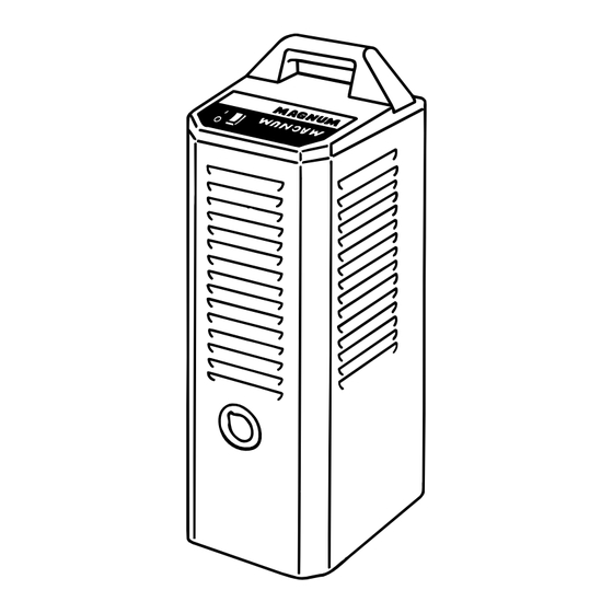
MAGNUM COOLERS 1 0-I AND 20-I
™
March, 1999
For use with machines having Code Number 9743, 9745, 9984, 9986,10266 and 10268
Safety Depends on You
Lincoln arc welding and cutting
equipment is designed and built
with safety in mind. However, your
overall safety can be increased by
proper installation ... and thought-
ful operation on your part. DO
NOT INSTALL, OPERATE OR
REPAIR THIS EQUIPMENT
WITHOUT
READING
THIS
MANUAL AND THE SAFETY
PRECAUTIONS CONTAINED
THROUGHOUT. And, most
importantly, think before you act
and be careful.
OPERATOR'S MANUAL
World's Leader in Welding and Cutting Products
Premier Manufacturer of Industrial Motors
• Sales and Service through Subsidiaries and Distributors Worldwide •
Cleveland, Ohio 44117-1199 U.S.A. TEL: 216.481.8100 FAX: 216.486.1751 WEB SITE: www.lincolnelectric.com
Advertisement
Table of Contents

Related Manuals for Lincoln Electric MAGNUM IM438-B


Summary of Contents for Lincoln Electric MAGNUM IM438-B
- Page 1 RETURN TO MAIN MENU IM438-B MAGNUM COOLERS 1 0-I AND 20-I ™ March, 1999 For use with machines having Code Number 9743, 9745, 9984, 9986,10266 and 10268 Safety Depends on You Lincoln arc welding and cutting equipment is designed and built with safety in mind.
-
Page 2: California Proposition 65 Warnings
351040, Miami, Florida 33135 or CSA Standard W117.2-1974. A Free copy of “Arc Welding Safety” booklet E205 is available from the Lincoln Electric Company, 22801 St. Clair Avenue, Cleveland, Ohio 44117-1199. BE SURE THAT ALL INSTALLATION, OPERATION, MAINTENANCE AND REPAIR PROCEDURES ARE PERFORMED ONLY BY QUALIFIED INDIVIDUALS. - Page 3 ELECTRIC SHOCK can kill. 3.a. The electrode and work (or ground) circuits are electrically “hot” when the welder is on. Do not touch these “hot” parts with your bare skin or wet clothing. Wear dry, hole-free gloves to insulate hands. 3.b.
- Page 4 WELDING SPARKS can cause fire or explosion. 6.a. Remove fire hazards from the welding area. If this is not possible, cover them to prevent the welding sparks from starting a fire. Remember that welding sparks and hot materials from welding can easily go through small cracks and openings to adjacent areas.
- Page 5 PRÉCAUTIONS DE SÛRETÉ Pour votre propre protection lire et observer toutes les instruc- tions et les précautions de sûreté specifiques qui parraissent dans ce manuel aussi bien que les précautions de sûreté générales suivantes: Sûreté Pour Soudage A L’Arc 1. Protegez-vous contre la secousse électrique: a.
- Page 6 EXPLANATION OF SYMBOLS THAT APPEAR ON THIS EQUIPMENT for selecting a QUALITY product by Lincoln Electric. We want you to take pride in operating this Lincoln Electric Company product ••• as much pride as we have in bringing this product to you!
-
Page 7: Table Of Contents
Lighted Power Switch ...B-1 Turning the System On...B-1 Magnum System Monitor...B-2 Demand System with Water Valve or Solenoid ...B-2 Surge Protection ...B-2 Fan Motor and Fan Blade ...B-2 Pump and Pump Pressure...B-2 Pump Failure ...B-3 Cooling Efficiency ...B-3 Accessories ...Section C Accessories ...C-1... -
Page 8: Installation
TECHNICAL SPECIFICATIONS – MAGNUM COOLERS 10-I AND 20-I Product No. Input Current Draw at Input Rated Current Draw Operating Pressure Shutdown Pressure (No delay after flow is stopped) Flow Range Typical Operating Flow Open Flow Reservoir Size Coolant Requirement Weight Reservoir Full Dimensions... -
Page 9: Product Description
The Magnum Cooler is capable of operating continu- ously;... -
Page 10: Electric Shock
INSTALLATION WARNING ELECTRIC SHOCK • Disconnect input power by removing plug from receptacle before working inside Cooler. • Use only grounded receptacle. • Do not remove the power cord ground prong. • Do not touch electrically “hot” parts inside Cooler. •... -
Page 11: Filling The Reservoir
The case front sheet metal design allows for ease of access to repair all internal components. The Phillips head fasteners used to secure the casing match the style of fasteners used in the pump head and other major components. In this manner, an operator can repair all major components in the unit using just a Phillips head screwdriver. -
Page 12: Horizontally Mounting Magnum Coolers To Lincoln Tig Power Sources
Cooler and insert the nipple into the connector nut so that the threaded end of the connector nut points away from the barbed end of the nipple. Twist the barbed end of the nipple into the hose until the shoulder of the nipple is flush with the end of the hose. - Page 13 FIGURE 3a C O O L E R H O L E " A " C O O L E R H O L E " B " C O O L E R H O L E " C " B R A C K E T H O L E "...
- Page 14 POWER SOURCE HEIGHT 16.44" (417.6mm) POWER SOURCE HEIGHT 16.44" (417.6mm) INSTALLATION FIGURE 3c Undercarriage Mounting Bracket Layout POWER SOURCE HEIGHT 21.50" (546.1mm) Cooler 10-I Mounting Scheme POWER SOURCE HEIGHT 21.50" (546.1mm) Cooler 20-I Mounting Scheme MAGNUM COOLER 10-I & 20-I POWER SOURCE HEIGHT 27.50"...
-
Page 15: Water Cooled Equipment Installation
WATER COOLED EQUIPMENT INSTALLATION NOTE: Magnum Coolers operate at 45 psi (3.0 bar) (310 kPa) of pressure for Cooler 10-I and 60 psi (4.0 bar) (414 kPa) of pressure for Cooler 20-I. When used in the demand system, the pressure in the supply hose to the water solenoid or valve can surge to 20 psi (1.4 bar) (138 kPa) above holding pressure just before shutdown. - Page 16 INSTALLATION FIGURE 5 Water Cooled MIG Gun Connection COOLANT COOLANT COOLANT COOLANT GUN CABLE FIGURE 6 Water Cooled Plasma System Connection COOLANT COOLANT COOLANT PLASMA CUTTING ELECTRODE POWER CABLE & AIR SOURCE COOLANT MAGNUM COOLER 10-I & 20-I...
-
Page 17: K440-1 Ln-7 Gma Wire Feeder With Gas And Water Solenoid Valve
A-10 K440-1 LN-7 GMA WIRE FEEDER WITH GAS AND WATER SOLENOID VALVE The K440-1 LN-7 GMA wire feeder is equipped with internal water lines and external connectors for attach- ment to a water cooled MIG gun and a Magnum Cooler. The water solenoid control of the K440-1 LN-7 GMA enables the feeder to trigger the demand system of a Magnum Cooler. -
Page 18: K529-10 Power Input Cable With Water And Gas Lines
A-11 K529-10 POWER INPUT CABLE WITH WATER AND GAS LINES The K529 power input cable connects from the front of a Lincoln power source to the back of LN-7 and LN-7 GMA wire feeders equipped with a water solenoid control. K529-10 is 10 ft. (3.0m) long and includes two water hoses and a gas line. -
Page 19: Operation
SAFETY PRECAUTIONS WARNING ELECTRIC SHOCK can kill. • Do not touch electrically live parts or electrode with skin or wet clothing. • Insulate yourself from work and ground. • Always wear dry insulating gloves. ------------------------------------------------------------------------ FUMES AND GASES can be danger- ous. -
Page 20: Magnum System Monitor
You will be able to hear the fan running and feel air flow out of the back of the unit when the Cooler is operating. The Cooler will run continuously when operated without a water solenoid or valve. If a water... -
Page 21: Pump Failure
The pressure switch allows the Cooler to run intermittently “On Demand” when connected to a water valve or solenoid only providing cooling water when it is needed. - Page 22 ROOM AIR PUMP COOLANT RETURN Approximate Cooling Rate and Recommended Use Product No. Max. Welding Current Max. Welding Current Max. Arc Current Misc. Applications The values listed are based on lab test results. Some applications may vary. OPERATION FIGURE 9 Circulation of Magnum Cooler HEATED AIR OUT...
-
Page 23: Accessories
PARTS DESCRIPTION FOR MAGNUM COOLER ACCESSORIES S20095-1 Pump Replacement Kit (60 psi) (4.0 bar) (414 kPa) for Magnum Cooler 20-I Models Includes: * (1) Complete 40-60 psi (3.0-4.0 bar) (310-414) kPa) Pressure switch assembly. * (1) Complete 60 psi (4.0 bar) (414 kPa) Pump with all internal components and hose connec tions. -
Page 24: Maintenance
WARNING ELECTRIC SHOCK • Disconnect input power by removing plug from receptacle before working inside Cooler. • Do not operate with covers removed. • Use only grounded receptacle. • Do not remove the power cord ground prong. • Do not touch electrically “hot” parts inside Cooler. •... -
Page 25: Troubleshooting
TROUBLESHOOTING GUIDE WARNING ELECTRIC SHOCK can kill. • Do not touch electrically live parts such as internal wiring. • Turn OFF input power at welding power source and accessory power source before installation or service. • Cooler must be connected to system ground per any National Electrical Code or any applicable local codes. - Page 26 Observe all Safety Guidelines detailed throughout this manual PROBLEMS (SYMPTOMS) Cooler does not operate with power switch on. (Switch pushed to "1" position.) Power switch blinks or flickers while coolant is flowing. (Continuous use, NO Water Valve or Solenoid in the system.) Using a water valve or solenoid and power switch blinks or flickers while...
- Page 27 (SYMPTOMS) Leak at inlet/outlet connector block. Torch or gun runs hot. Fan operates but there is low coolant flow. Fan operates but there is no coolant flow. If for any reason you do not understand the test procedures or are unable to perform the tests/repairs safely, contact your Local Lincoln Authorized Field Service Facility for technical troubleshooting assistance before you proceed.
- Page 28 Observe all Safety Guidelines detailed throughout this manual PROBLEMS (SYMPTOMS) Pump operates, but fan does not. Cooler trips outlet circuit breaker. If for any reason you do not understand the test procedures or are unable to perform the tests/repairs safely, contact your Local Lincoln Authorized Field Service Facility for technical troubleshooting assistance before you proceed.
- Page 29 DIAGRAMS MAGNUM COOLER 10-I & 20-I...
- Page 30 COOLER 10 COOLER 10-I 50/60 NUMBERS EMBOSSED ON SWITCH HOUSING COOLER 20 COOLER 20-I 50/60 NUMBERS EMBOSSED ON SWITCH HOUSING COOLER 10 COOLER 10-I 50/60 NUMBERS EMBOSSED ON SWITCH HOUSING COOLER 20 COOLER 20-I 50/60 NUMBERS EMBOSSED ON SWITCH HOUSING DIAGRAMS MAGNUM COOLERS CODES 9743 THRU 9746 B L A C K...
- Page 31 ● WARNING ● Spanish ● AVISO DE PRECAUCION ● French ● ATTENTION ● ● German WARNUNG ● Portuguese ● ATENÇÃO ● Japanese Chinese Korean Arabic READ AND UNDERSTAND THE MANUFACTURER’S INSTRUCTION FOR THIS EQUIPMENT AND THE CONSUMABLES TO BE USED AND FOLLOW YOUR EMPLOYER’S SAFETY PRACTICES. SE RECOMIENDA LEER Y ENTENDER LAS INSTRUCCIONES DEL FABRICANTE PARA EL USO DE ESTE EQUIPO Y LOS CONSUMIBLES QUE VA A UTILIZAR, SIGA LAS MEDIDAS DE SEGURIDAD DE SU SUPERVISOR.
- Page 32 ● ● Keep your head out of fumes. Turn power off before servicing. ● Use ventilation or exhaust to remove fumes from breathing zone. ● Los humos fuera de la zona de res- ● Desconectar el cable de ali- piración. mentación de poder de la máquina ●...
Need help?
Do you have a question about the MAGNUM IM438-B and is the answer not in the manual?
Questions and answers