Table of Contents
Advertisement
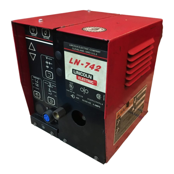
LN- 742 & LN- 742H Wire Feeders
For use with machines having Code Numbers:
Safety Depends on You
Lincoln arc welding and cutting
equipment is designed and built
with safety in mind. However, your
overall safety can be increased by
proper installation ... and thought-
ful operation on your part. DO
NOT INSTALL, OPERATE OR
REPAIR THIS EQUIPMENT
WITHOUT
READING
THIS
MANUAL AND THE SAFETY
PRECAUTIONS CONTAINED
THROUGHOUT. And, most
importantly, think before you act
and be careful.
• Sales and Service through Subsidiaries and Distributors Worldwide •
Cleveland, Ohio 44117-1199 U.S.A. TEL: 216.481.8100 FAX: 216.486.1751 WEB SITE: www.lincolnelectric.com
RETURN TO MAIN MENU
10027
10028
10048
10049
10238
10239
10240
10241
OPERATOR'S MANUAL
• World's Leader in Welding and Cutting Products •
Copyright © 2005 Lincoln Global Inc.
IM476-A
August, 2005
Advertisement
Table of Contents

Related Manuals for Lincoln Electric LN-742 LN-742


Summary of Contents for Lincoln Electric LN-742 LN-742
- Page 1 • Sales and Service through Subsidiaries and Distributors Worldwide • Cleveland, Ohio 44117-1199 U.S.A. TEL: 216.481.8100 FAX: 216.486.1751 WEB SITE: www.lincolnelectric.com RETURN TO MAIN MENU 10027 10028 10048 10049 10238 10239 10240 10241 Copyright © 2005 Lincoln Global Inc. IM476-A August, 2005...
-
Page 2: California Proposition 65 Warnings
351040, Miami, Florida 33135 or CSA Standard W117.2-1974. A Free copy of “Arc Welding Safety” booklet E205 is available from the Lincoln Electric Company, 22801 St. Clair Avenue, Cleveland, Ohio 44117-1199. BE SURE THAT ALL INSTALLATION, OPERATION, MAINTENANCE AND REPAIR PROCEDURES ARE PERFORMED ONLY BY QUALIFIED INDIVIDUALS. -
Page 3: Electric Shock Can Kill
ELECTRIC SHOCK can kill. 3.a. The electrode and work (or ground) circuits are electrically “hot” when the welder is on. Do not touch these “hot” parts with your bare skin or wet clothing. Wear dry, hole-free gloves to insulate hands. - Page 4 WELDING SPARKS can cause fire or explosion. 6.a. Remove fire hazards from the welding area. If this is not possible, cover them to prevent the welding sparks from starting a fire. Remember that welding sparks and hot materials from welding can easily go through small cracks and openings to adjacent areas.
- Page 5 PRÉCAUTIONS DE SÛRETÉ Pour votre propre protection lire et observer toutes les instructions et les précautions de sûreté specifiques qui parraissent dans ce manuel aussi bien que les précautions de sûreté générales suiv- antes: Sûreté Pour Soudage A L’Arc 1. Protegez-vous contre la secousse électrique: a.
- Page 6 The code number is especially important when identifying the correct replacement parts. - Register your machine with Lincoln Electric either via fax or over the Internet. • For faxing: Complete the form on the back of the warranty statement included in the literature packet accompanying this machine and fax the form per the instructions printed on it.
-
Page 7: Table Of Contents
Safety ............Installation . -
Page 8: Installation
TECHNICAL SPECIFICATIONS – LN-742 SYSTEM LN-742 LN-742H SYSTEM ELECTRODE LN-742 SOLID LN-742H SOLID LN-742 CORED LN-742H CORED TEMPERATURE RATING (ALL MODELS) OPERATING STORAGE BOTH LN-742 AND LN-742H 2 ROLL FEEDER WITHOUT WIRE STAND 2 ROLL FEEDER WITH WIRE STAND (K377) 4 ROLL FEEDER WITHOUT WIRE STAND 4 ROLL FEEDER... -
Page 9: Mounting Location
Turn input power off before connecting the LN-742 wire feeder. ------------------------------------------------------------------------ For connecting an LN-742 to a specific Lincoln power source, follow steps 1 through 5, and refer to the connection diagram in Figure A.3. The welding cable used must be sized according to the current and the duty cycle of the application. - Page 10 Connect the remaining end of the control cable with the eight-socket cable plug to the mating receptacle on the LN-742. Referring to Figure A.2, install the input cable under the wire reel mounting stand strain relief clamp. Remove the screws holding the clamp to the base of wire reel mounting assembly.
- Page 11 FIGURE A.3 – LN-742 WIRE FEEDER TO LINCOLN POWER SOURCE – CONNECTION DIAGRAM. LINCOLN POWER SOURCE TO WORK ELECTRODE CABLE K=42 E=77 14-SOCKET BOX RECEPTACLE, FRONT VIEW AND 14-PIN CABLE PLUG, REAR VIEW LEAD FUNCTION TRIGGER CIRCUIT TRIGGER CIRCUIT OUTPUT CONTROL...
-
Page 12: Work Cable
000 (85 mm GUN AND CABLE ASSEMBLIES The LN-742 can be used with several guns. In most cases, Lincoln guns and cables are shipped assembled, ready to weld. Use the gun and cable assembly for the electrode type (solid, Outershield , or Innershield) and electrode size to be used. -
Page 13: Water Connections (For Water Cooled Guns
The maximum water pressure permitted for use with the LN-742 is 55 psi (3.8 bar). NOTE: If not using a Lincoln water cooler, and if your water cooling device is not designed for use with a waterline solenoid valve, you may remove the solenoid and screw the male fitting (after applying sealant) directly into the brass manifold block. -
Page 14: Gmaw Shielding Gas Hookup
GMAW SHIELDING GAS HOOKUP WARNING Gas under pressure is explosive. Always keep gas cylinders in an upright position and chained to the undercarriage support. See American National Standard Z-49.1, “Safety In Welding And Cutting”, published by the American Welding Society. ------------------------------------------------------------------------ FIGURE A.6 –... -
Page 15: Operation
42 VAC auxiliary power and a 14- pin connector receptacle, such as the Invertec V300- PRO, V350-PRO, DC-400, DC-600, DC-655 DC-650- PRO, or Lincoln CV type power sources. ear, body The LN-742 is capable of the following wire feed ranges: •... -
Page 16: Controls And Settings
• 0.045 to 5/64 in. (1.2 to 2.0 mm) cored wire for Innershield processes. The LN-742H is capable of the following wire feed ranges: • 0.025 to 0.045 in. (0.6 to 1.2 mm) solid wire for gas- metal-arc or CV submerged arc processes. •... -
Page 17: Acceleration Setting
FUNCTION SELECTION CONTROLS. This control enables the operator to select the function that will be displayed as shown by the indicator lights. Pressing the key causes the mode lights to sequence (from top to bottom). Settings displayed in the LED display are adjusted using the setting adjustment arrows to the left of the LED display. - Page 18 OPERATION FIGURE B.2 – INSTALLING DRIVE ROLLS ON A TWO-ROLL FEEDER. CLAMPING COLLAR SPACER (IF REQUIRED) DRIVE ROLL HALVES OUTPUT SHAFT LARGE GUIDE TUBE DETAIL RADIUS OUTGOING DRIVE GUIDE ROLL TUBE OUTGOING GUIDE TUBE INSERT INCOMING IDLE GUIDE ROLL TUBE SMALL RADIUS LN-742 &...
-
Page 19: Changing Drive Rolls For Four- Roll Wire Feeders
3. Remove the hex head screw and clamping collar. Remove the drive roll from the shaft. 4. The new roll to be installed is stamped for the size wire to be fed. An “A” after the size indicates aluminum wire. Remove the rolls from the kit and wipe them clean. - Page 20 OPERATION FIGURE B.3 – INSTALLING DRIVE ROLLS ON A FOUR-ROLL FEEDER. CLAMPING COLLAR DRIVE ROLL HALVES SPACER (IF REQUIRED) OUTPUT SHAFT LARGE GUIDE TUBE DETAIL RADIUS OUTGOING GUIDE TUBE OUTGOING GUIDE TUBE INSERT MIDDLE IDLE GUIDE ROLL TUBE SMALL RADIUS LN-742 &...
-
Page 21: Idle Roll Pressure Setting
Two-roll wire feeders: 1. Press the end of the gun against a solid object that is electrically isolated from the welder output and press the trigger for several seconds. 2. If the wire “birdnests”, jams, or breaks at the drive roll, the idle roll pressure is set too high. -
Page 22: Wire Loading
WIRE LOADING Loading a 22 to 30 Lb. (10 to 14 kg) Readi-Reel Package Using the Molded Plastic K363-P Readi-Reel Adapter: The Spindle should be located in the LOWER mounting hole of the K1524-1 Universal Stand if used. 1) Depress the Release Bar on the Retaining Collar and remove it from the spindle. - Page 23 TO MOUNT 10 TO 44 lb (4.5 to 20 kg) SPOOLS (12 in./300 mm DIAMETER) OR 13-14 lb (6 kg) INNERSHIELD COILS: The spindle should be located in the lower mounting hole of the K1524-1 Universal Stand if used. [For 8 in. (200 mm) spools, a K468 spindle adapter must first be slipped onto the spindle.] [For 13 to 14 lb (6 kg) Innershield coils, a K435 Coil Adapter must be used.]...
- Page 24 B-10 WIRE REEL LOADING – 50 AND 60 LB COILS (K303 OR K376 WIRE REEL STAND) ADJUSTABLE WIRE REEL BRAKE The mount for standard 50 and 60 pound electrode coils includes a two-position brake assembly. Generally the brake should be at the inner position (nearest to the wire reel shaft) for wire feed speeds below 400 in./min (10 m/min).
- Page 25 B-11 WIRE REEL LOADING – 50 AND 60 LB COILS (K1524-1 UNIVERSAL WIRE REEL STAND) TO MOUNT A 50 to 60 lb (22.7 to 27.2 kg) COIL: (USING K1504-1 COIL REEL) (FOR 50 to 60 lb READI-REELS A K438 READI-REEL ADAPTER MUST BE USED.) The spindle should be located in the UPPER mount- ing hole.
-
Page 26: Making A Weld
B-12 MAKING A WELD 1. Use only constant voltage power type sources. If using a multiple process power source, be sure it is set for constant voltage output per instructions in the manual for the power source. 2. Set the power source polarity switch or properly connect the electrodes and work leads for the correct electrode polarity. -
Page 27: Accessories
GENERAL The following is a list of the accessories that can be used with the LN-742 wire feeder. Product Number Name K163 Undercarriage K178-1 Mounting Platform K589-1 Remote Control Kit K590-1 Water Solenoid Kit K590-2 Water Connection Kit K857 Remote Voltage Control Kit Magnetic Separator K310 Flux Screen... -
Page 28: Flux System Components
ACCESSORIES K857 can be installed on the LN-742 when it is used with newer Lincoln power sources that are equipped with a 6-socket ms-type receptacle or K864 14-pin connector adapter for connection of the plug on the 28 ft (8.5 m) control cable of the K857. -
Page 29: Power Input Cables
Coarse particles and/or magnetic particles will stop the flux feeding process. New Lincoln flux is properly screened at the factory. All reclaimed flux must be separately screened through a vibrating screen with 0.065 in. -
Page 30: Submerged Arc Guns
K468 Spindle Adapter is available. K363P 22 TO 30 LB READI-REEL ADAPTER Adapts Lincoln Readi-Reel coils of 22 and 33 lb (10 and 14 kg) to a 2 in. (51 mm) spindle. Durable, molded plastic, one piece construction. Designed for easy loading -- adapter remains on spindle for quick changeover. -
Page 31: Attaching The Wire Reel Stand
2 in. (51 mm) O.D. spindles. For K377 and K445, or K303 and K376 with optional K162H adapter. K438 50 TO 60 LB READI-REEL ADAPTER Adapts Lincoln Readi-Reel coils of 50 to 60 lb (22.7 to 27.7 kg) to a 2 in. (51 mm) spindle. (Included with K445.) -
Page 32: Drive Roll Kits
DRIVE ROLL KITS Table C-2 lists the appropriate drive roll kits for each type of wire used. TABLE C.2 – DRIVE ROLL KIT NUMBERS. Steel Wire Sizes 0.068-3/32 in. (1.7-2.4 mm) Cored 1/16 in. (1.6 mm) Cored or Solid 0.045-0.052 in. (1.2-1.3 mm) Solid 0.045-0.052 in. -
Page 33: Maintenance
ROUTINE MAINTENANCE DRIVE ROLLS AND GUIDE TUBES After feeding every coil of wire, inspect the drive roll section. Clean the assembly as necessary. Do not use solvent to clean the drive roll assembly as it may wash the lubricant out of the bearings. The drive rolls and guide tubes are stamped with the wire sizes they will feed. -
Page 34: How To Use Troubleshooting Guide
HOW TO USE TROUBLESHOOTING GUIDE Service and Repair should only be performed by Lincoln Electric Factory Trained Personnel. Unauthorized repairs performed on this equipment may result in danger to the technician and machine operator and will invalidate your factory warranty. For your safety and to avoid Electrical Shock, please observe all safety notes and precautions detailed throughout this manual. - Page 35 LN-742 has input power applied. If for any reason you do not understand the test procedures or are unable to perform the tests/repairs safely, contact your Local Lincoln Authorized Field Service Facility for technical troubleshooting assistance before you proceed. TROUBLESHOOTING...
- Page 36 If for any reason you do not understand the test procedures or are unable to perform the tests/repairs safely, contact your Local Lincoln Authorized Field Service Facility for technical troubleshooting assistance before you proceed. TROUBLESHOOTING POSSIBLE CAUSE 1.
- Page 37 If for any reason you do not understand the test procedures or are unable to perform the tests/repairs safely, contact your Local Lincoln Authorized Field Service Facility for technical troubleshooting assistance before you proceed. TROUBLESHOOTING POSSIBLE CAUSE 1.
- Page 38 (Microprocessor RAM error.) If for any reason you do not understand the test procedures or are unable to perform the tests/repairs safely, contact your Local Lincoln Authorized Field Service Facility for technical troubleshooting assistance before you proceed. TROUBLESHOOTING POSSIBLE CAUSE 1.
- Page 39 If for any reason you do not understand the test procedures or are unable to perform the tests/repairs safely, contact your Local Lincoln Authorized Field Service Facility for technical troubleshooting assistance before you proceed. TROUBLESHOOTING POSSIBLE CAUSE 1.
- Page 40 “blast-offs”. The weld bead may be ropy and narrow. If for any reason you do not understand the test procedures or are unable to perform the tests/repairs safely, contact your Local Lincoln Authorized Field Service Facility for technical troubleshooting assistance before you proceed. TROUBLESHOOTING POSSIBLE CAUSE 1.
- Page 41 DIAGRAMS LN-742 & LN-742H...
- Page 42 NOTES LN-742 & LN-742H...
- Page 43 NOTES LN-742 & LN-742H...
- Page 44 NOTES LN-742 & LN-742H...
- Page 45 NOTES LN-742 & LN-742H...
- Page 46 ● WARNING ● Spanish ● AVISO DE PRECAUCION ● French ● ATTENTION ● ● German WARNUNG ● Portuguese ● ATENÇÃO ● Japanese Chinese Korean Arabic ● ● ● ● ● ● ● ● ● ●...
- Page 47 ● ● ● ● ● ● ● ● ● ● ● ● ● ● ● ● ● ● Spanish ● PRECAUCION French ● ATTENTION ● German WARNUNG Portuguese ● ● Japanese Chinese Korean Arabic WARNING AVISO DE ATENÇÃO...
- Page 48 • World's Leader in Welding and Cutting Products • • Sales and Service through Subsidiaries and Distributors Worldwide • Cleveland, Ohio 44117-1199 U.S.A. TEL: 216.481.8100 FAX: 216.486.1751 WEB SITE: www.lincolnelectric.com...
Need help?
Do you have a question about the LN-742 LN-742 and is the answer not in the manual?
Questions and answers