Table of Contents
Advertisement
IM901-A
RETURN TO MAIN MENU
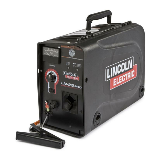
LN-25™ PRO
January, 2010
For use with machines having Code Number: 11387, 11388, 11507, 11508
Safety Depends on You
Lincoln arc welding and cutting
equipment is designed and built with
safety in mind. However, your overall
safety can be increased by proper
installation ... and thoughtful opera-
tion on your part.
DO NOT
INSTALL, OPERATE OR REPAIR
THIS EQUIPMENT WITHOUT
READING THIS MANUAL AND
THE SAFETY PRECAUTIONS
CONTAINED THROUGHOUT.
And, most importantly, think before
you act and be careful.
IP23
IEC 60974-5
OPERATOR'S MANUAL
Copyright © Lincoln Global Inc.
• World's Leader in Welding and Cutting Products •
• Sales and Service through Subsidiaries and Distributors Worldwide •
Cleveland, Ohio 44117-1199 U.S.A. TEL: 216.481.8100 FAX: 216.486.1751 WEB SITE: www.lincolnelectric.com
Advertisement
Table of Contents

Subscribe to Our Youtube Channel
Related Manuals for Lincoln Electric LN-25 PRO IM901-A


Summary of Contents for Lincoln Electric LN-25 PRO IM901-A
- Page 1 IM901-A RETURN TO MAIN MENU LN-25™ PRO January, 2010 For use with machines having Code Number: 11387, 11388, 11507, 11508 Safety Depends on You Lincoln arc welding and cutting equipment is designed and built with safety in mind. However, your overall safety can be increased by proper installation ...
-
Page 2: California Proposition 65 Warnings
351040, Miami, Florida 33135 or CSA Standard W117.2-1974. A Free copy of “Arc Welding Safety” booklet E205 is available from the Lincoln Electric Company, 22801 St. Clair Avenue, Cleveland, Ohio 44117-1199. bE SURE THAT ALL INSTALLATION, OPERATION, MAINTENANCE AND REPAIR PROCEDURES ARE PERFORMED ONLY bY QUALIFIED INDIVIDUALS. - Page 3 SAFETY...
- Page 4 SAFETY...
- Page 5 PRÉCAUTIONS DE SÛRETÉ Pour votre propre protection lire et observer toutes les instructions et les précautions de sûreté specifiques qui parraissent dans ce manuel aussi bien que les précautions de sûreté générales suiv- antes: Sûreté Pour Soudage A L’Arc 1. Protegez-vous contre la secousse électrique: a.
- Page 6 Electric for advice or information about their use of our products. We respond to our customers based on the best information in our posses- sion at that time. Lincoln Electric is not in a position to warrant or guarantee such advice, and assumes no liability, with respect to such infor- mation or advice.
-
Page 7: Table Of Contents
TAbLE OF CONTENTS –––––––––––––––––––––––––––––––––––––––––––––––––––––––––––––––––––––––––––––––– Installation...Section A Technical Specifications ...A-1 Safety Precautions ...A-2 Location ...A-2 High Frequency Protection ...A-2 Weld cable Sizes ...A-2 Cable Connections ...A-3 Shielding Gas Connection ...A-3 Wire Drive Configuration ...A-4 Changing The Gun Receiver Bushing ...A-4 Procedure to Install Drive Rolls and Wire Guides ...A-4 Pressure Arm Adjustment ...A-5 Loading Spools of Wire ...A-5 Gun Connections...A-5... -
Page 8: Installation
TECHNICAL SPECIFICATIONS – LN-25™ PRO ACROSS THE ARC MODEL INPUT VOLTAGE and CURRENT INPUT VOLTAGE ± 10% 15-110 VDC RATED OUTPUT @ 104°F (40°C) DUTY CYCLE 60% rating 100% rating GEARING - WIRE FEED SPEED RANGE-WIRE SIzE GEARING WFS RANGE Extra torque 30 –... -
Page 9: Safety Precautions
SAFETY PRECAUTIONS WARNING ELECTRIC SHOCK CAN KILL. • Turn the input power OFF at the disconnect switch or fuse box before attempting to connect or disconnect input power lines, out- put cables or control cables. • Only qualified personnel should perform this installation. •... -
Page 10: Cable Connections
CAbLE CONNECTIONS There is one circular connector for the gun trigger on the front of the LN-25™ PRO. Function Wiring 5-pin trigger Trigger connector for Not used push-guns Common only. Not used Not used INSTALLATION SHIELDING GAS CONNECTION • Keep cylinder away from areas where it may be damaged. -
Page 11: Wire Drive Configuration
WIRE DRIVE CONFIGURATION (See Figure A.2) CHANGING bUSHING WARNING ELECTRIC SHOCK can kill. • Turn the input power OFF at the welding power source before instal- lation or changing drive rolls and/or guides. • Do not touch electrically live parts. •... -
Page 12: Pressure Arm Adjustment
PRESSURE ARM ADJUSTMENT WARNING ELECTRIC SHOCK can kill. • Turn the input power OFF at the weld- ing power source before installation or changing drive rolls and/or guides. • Do not touch electrically live parts. • When inching with the gun trigger, electrode and drive mechanism are "hot"... -
Page 13: Power Source To Ln-25™ Pro Cable Connection Diagrams
POWER SOURCE TO LN-25™ PRO CAbLE CONNECTION DIAGRAMS ACROSS THE ARC SET-UPS CC Power Sources with Output Terminals Always Hot (See Figure A.5) CC Power Source Ranger 250, 250 LPG Ranger 305G, 305D Commander 300 Vantage 300, 400, 500 Air Vantage 500 Ranger 10,000 Ranger 3 phase SAE 400 with CV adapter... - Page 14 CV Power Sources with Stud Connectors and no Remote/Local Switch. (See Figure A.7) Jumper CV-400 CV-655 Place CV/CC switch in the feeder in the "CV" position. CV Power Source with Twist-Mate Connectors and Remote/Local Switch. (See Figure A.8) V350-Pro Place CV/CC switch in the feeder in the "CV" position. INSTALLATION FIGURE A.7 LN-25™...
- Page 15 CV Power Source with Twist-Mate Connectors and no Remote/Local Switch. (See Figure A.9) Jumper CV-250 CV-300 CV-305 Place CV/CC switch in the feeder in the "CV" position. INSTALLATION FIGURE A.9 LN-25™ PRO Electrode Work K2613-1 K2613-2 KP1695-XX KP1696-XX KP1697-XX See Magnum Literature K1841- K484 LN-25™...
-
Page 16: Safety Precautions
SAFETY PRECAUTIONS READ AND UNDERSTAND ENTIRE SECTION bEFORE OPERATING MACHINE. WARNING • ELECTRIC SHOCK CAN KILL. Unless using COLD FEED fea- ture, when feeding with gun trig- ger, the electrode and drive mechanism are always electri- cally energized and could remain energized several sec- onds after the welding ceases.. -
Page 17: Definition Of Welding Terms
DEFINITION OF WELDING TERMS • Wire Feed Speed • Constant Current • Constant Voltage GMAW • Gas Metal Arc welding SMAW • Shielded Metal Arc welding FCAW • Flux Core Arc Welding GENERAL DESCRIPTION General Physical Description The LN-25™ PRO is specially engineered to be the most rugged portable wire feeder available. -
Page 18: Case Front Controls
(See Customer Assistance Policy in the front of this Instruction Manual) CASE FRONT CONTROLS 1. ANALOG VOLTMETER The analog voltmeter shows the voltage between electrode and work. On across the arc models, the voltmeter shows open circuit voltage when the wire feeder is not welding. -
Page 19: Operation
2. WIRE FEED SPEED KNOb The large, calibrated wire feed speed knob makes for easy and accurate adjustment of the wire feed speed. The knob rotates 3/4 turn. Turn the knob clockwise to increase the wire feed speed, and counter clockwise to reduce the wire feed speed. Models with analog voltmeters have a calibrated scale printed around the wire feed speed knob using "in/min"... -
Page 20: Thermal Led, Motor Overload
Perform regular maintenance and cleaning on the gun liner, conduit and gun. Always use quality electrode, such as L-50 or L-56 from Lincoln Electric. 6. POLARITY LED The Polarity LED - P O L A R I T É... -
Page 21: Internal Controls
INTERNAL CONTROLS ITEM 2 Step Trigger Interlock Switch CV / CC Switch Pressure Adjustment Arm Optional Timer Kit (See Accessories Section) Spool Retainer Spindle Brake Gun Bushing Thumb Screw for securing the welding Gun Socket Head Cap Screw for securing the Gun Bushing Drive Hubs Inlet Wire Guide Cold Feed Pushbutton... -
Page 22: Internal Controls Decription
INTERNAL CONTROLS DESCRIPTION (See Figure B.2) 2 Step - Trigger Interlock Switch The 2 Step - Trigger Interlock switch changes the function of the gun trigger. 2 Step trigger opera- tion turns welding on and off in direct response to the trigger. Trigger Interlock operation allows welding to continue when the trig- ger is released for comfort on long... -
Page 23: Constant Current Wire Welding
For these reasons, Lincoln Electric does NOT recom- mend constant current semiautomatic welding for applications which need to meet specified weld metal chemical or mechanical property requirements or weld quality requirements. -
Page 24: Rear Controls
REAR CONTROLS: c o n n e c t i o n s I T E M D E S C R I P T I O N O p t i o n a l W a t e r c o o l e d g u n F l o w M e t e r B a l l G a s P u r g e P u s h b u t t o n S h i e l d i n g G a s I n l e t... -
Page 25: Gas Purge Pushbutton
b-10 GAS PURGE PUSHbUTTON The gas solenoid valve will energize but neither the power source output nor the drive motor will be turned on. The Gas Purge switch is useful for setting the proper flow rate of shielding gas. Flow meters should always be adjusted while the shielding gas is flowing. -
Page 26: Accessories
FACTORY INSTALLED EQUIPMENT • K1500-2 Gun Receiver Bushing. DRIVE ROLL KITS WIRE TYPE ELECTRODE SIzE Steel Wires: .023-.030 (0.6-0.8mm) .035 (0.9mm) .045 (1.2mm) .052 (1.4mm) 1/16 (1.6mm) .035,.045 (0.9, 1.2mm) .040 (1.0mm) .030-.035" (0.8-0.9mm) Cored Wires: .040-.045" (1.0-1.2mm) .052" (1.4mm) 1/16"... - Page 27 K1796-xx AWG 1/0 Co-Axial Power Cable K2593-xx AWG #1 Coaxial Power Cable K1803-1 Work and Feeder Cables Package K1840-xx Weld Power Cable, Twist-Mate to K1842-xx Weld Power Cable, Lug to Lug ACCESSORIES Includes: 1/0 Coaxial weld cable of length "xx". Ends of the weld cable have lug con- nections.
- Page 28 Control Cable K1797-xx Adapter for Competitive Power K2335-1 Sources Jumper Plug Kit K484 K1520-1 (requires Digital 42 Volt Transformer Kit Meter/remote control kit) K1798 Adapter Cable for Control Cable to (requires Terminal Strip Power Sources remote control ACCESSORIES Includes: 14 pin to 14 pin wire feeder to power source control cable.
- Page 29 K910-1 Ground Clamp K910-2 Ground Clamp Gun Receiver Bushing (for guns K1500-1 with K466-1 Lincoln gun connec- tors; Innershield and Subarc guns) Gun Receiver Bushing (for guns with K466-2, K466-10 Lincoln gun K1500-2 connectors; Magnum 200/300/400 guns and compatible with Tweco® #2-#4) Gun Receiver Bushing (for guns K1500-3...
- Page 30 Gun Receiver Bushing (for gun K1500-4 with K466-3 Lincoln gun connec- tors; compatible with Miller® guns.) K1500-5 Gun Receiver Bushing (compatible with Oxo® guns.) K489-7 Gun Receiver Bushing (for Lincoln Fast-Mate guns.) K435 Spindle Adapter, for mounting 14 lb. (6.4 kg) Innershield Coils on 2 in (51 mm) spindles.
- Page 31 INSTALLATION OF THE K590-6 WATER COOLING KIT WARNING ELECTRIC SHOCK can kill. • Turn the input power OFF at the dis- connect switch before working on this equipment. • Do not touch electrically hot parts. • Only qualified personnel should install, use or service this equipment.
-
Page 32: Maintenance
SAFETY PRECAUTIONS WARNING ELECTRIC SHOCK can kill. • Turn the input power OFF at the welding power source before installation or changing drive rolls and/or guides. • Do not touch electrically live parts. • When inching with the gun trigger, electrode and drive mechanism are "hot"... - Page 33 The LN-25™ PRO flow meter cannot be calibrated. If the flow meter reads incorrectly, check for leaks or kinks in the gas hose. Replace the flow meter if neces- sary. Wire Feed Speed Validation (See Figure D.1) Calibration of the LN-25™ PRO may be required when the p.c.
-
Page 34: How To Use Troubleshooting Guide
HOW TO USE TROUbLESHOOTING GUIDE Service and Repair should only be performed by Lincoln Electric Factory Trained Personnel. Unauthorized repairs performed on this equipment may result in danger to the technician and machine operator and will invalidate your factory warranty. For your safety and to avoid Electrical Shock, please observe all safety notes and precautions detailed throughout this manual. -
Page 35: Digital Display Models Error Codes
Observe all Safety Guidelines detailed throughout this manual PRObLEMS (SYMPTOMS) Fault Code Err 81 Motor overload, long term. Err 82 Motor overload, short term. If for any reason you do not understand the test procedures or are unable to perform the tests/repairs safely, contact your Local Lincoln Authorized Field Service Facility for technical troubleshooting assistance before you proceed. - Page 36 3. Blow dirt out of the liner with low pressure (40psi or less). Replace the liner if worn. 4. Use only clean electrode. Use quality electrode, like L-50 or L-56 from Lincoln Electric. 5. Replace the contact tip. 6. Verify the proper parts are installed.
- Page 37 Observe all Safety Guidelines detailed throughout this manual PRObLEMS (SYMPTOMS) Wire feed speed consistently oper- ates at the wrong value. The speed changes when the wire feed speed knob is adjusted. The wire feed speed stuck at 200- 300 in/min and there is no change when the wire feed speed knob is adjusted.
- Page 38 DIAGRAMS LN-25™ PRO ACROSS THE ARC MODEL...
- Page 39 DIAGRAMS LN-25™ PRO ACROSS THE ARC MODEL...
-
Page 40: Dimension Print
DIMENSION PRINT LN-25™ PRO ACROSS THE ARC MODEL... - Page 41 NOTES LN-25™ PRO ACROSS THE ARC MODEL...
- Page 44 • World's Leader in Welding and Cutting Products • • Sales and Service through Subsidiaries and Distributors Worldwide • Cleveland, Ohio 44117-1199 U.S.A. TEL: 216.481.8100 FAX: 216.486.1751 WEB SITE: www.lincolnelectric.com...
Need help?
Do you have a question about the LN-25 PRO IM901-A and is the answer not in the manual?
Questions and answers