Table of Contents
Advertisement
Advertisement
Table of Contents

Related Manuals for Tharo Systems H-427


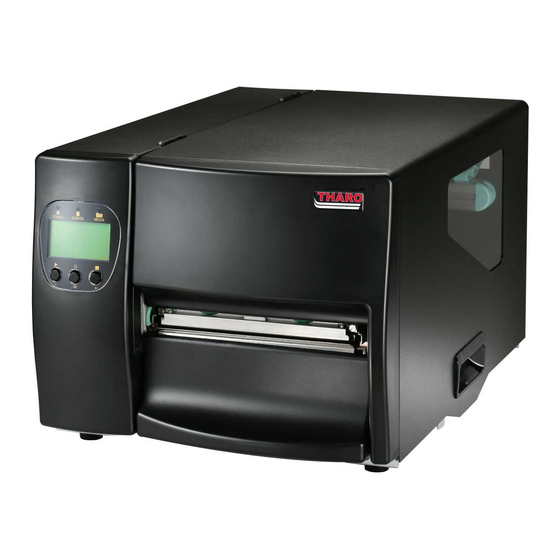
Summary of Contents for Tharo Systems H-427
- Page 1 H H H H - - - - 427 / H 427 / H 427 / H- - - - 436 Thermal Transfer Printer 427 / H 436 Thermal Transfer Printer 436 Thermal Transfer Printer 436 Thermal Transfer Printer Parts / Service Manual Parts / Service Manual Parts / Service Manual Parts / Service Manual...
-
Page 2: Table Of Contents
Specifications ....................3 Parts Listing ....................4 2.01 General Overview .......................4 2.02 Covers ..........................5 2.03 LCD Panel Module......................6 2.04 Main Board ..........................7 2.05 Platen Roller ........................8 2.06 Motor Module........................9 2.07 Thermal Printhead Module ....................10 2.08 Label Gap Sensor Parts....................11 2.09 Ribbon Module .........................12 2.10 Label Supply Guide......................13 2.11 Power Switch ........................14 2.12 Optional-Cutter Parts .......................15... - Page 3 PS/2 Interface..........................30 Optional Applicator Interface ....................30 Appendix B. Error Messages/Troubleshooting ...... 31 Self-Test ............................31 Dump Mode ..........................31 LCD Error Messages and Descriptions..................32 Problems and Recommended Solutions ................33 Appendix C. Maintenance and Adjustment ......34 Thermal Printhead Cleaning....................34 Printhead Module Installation / Removal Instructions ............35 Printhead Print Line Adjustment ....................36 Thermal Printhead Balance Adjustment ................37 Ribbon Tension Adjustment ....................37...
-
Page 4: Specifications
Specifications Model H - 427 H - 436 Resolution 203 dpi (8 dot/mm) 300 dpi (12 dot/mm) Print Mode Thermal Transfer / Direct Thermal 32 Bit Memory 4MB Flash, 16MB SDRAM Print Speed 50.8 mm (2”) ~ 177.8 mm (7”)/sec 50.8 mm (2”) ~ 152.4 mm (6”)/sec Print Length 5 mm (0.20”) ~ 4572 mm (180”) -
Page 5: Parts Listing
Parts Listing 2.01 General Overview Item Part No. Description Remarks 700-050000-001 LABEL ROLL GUIDE Part Group RIBBON MODULE Part Group MECHANISM 700-031903-021 BOTTOM FRONT COVER 700-031703-031 LEFT PANEL 720-058000-010 TOP RIGHT COVER... -
Page 6: Covers
2.02 Covers NOTE: Use Part Number 023-22P013-060 for LCD Front Panel (left) #4 NOTE: Use Part Number 023-22P011-060 for Front Panel (upper right) #2 NOTE: Use Part Number 023-22P015-060 for Front Panel Kit (lower right) #3 Item Part No. Description Remarks 720-058000-010 TOP RIGHT COVER... -
Page 7: Lcd Panel Module
2.03 LCD Panel Module NOTE: Use Part Number 023-22P017-060 for replacement Strip Sensor Assembly NOTE: Use Part Number 023-22P014-060 for replacement LCD Front Panel Part No. Description Remarks 1. LCD Left Panel Module Parts 700-041000-001 LCD PANEL 755-006300-010 NAME PLATE 700-031703-031 LEFT PANEL 160-000103-030... -
Page 8: Main Board
2.04 Main Board Part No. Description Remarks 710-045100-000 MIDDLE PLATE 023-22P006-060 MAIN PCB ASSEMBLY 765-130064-142 MACHINE SCREW/P/NI/M3*6 160-100019-000 RIBBON SENSOR OUT ASSEMBLY... -
Page 9: Platen Roller
2.05 Platen Roller NOTE: Use Part Number 023-22P009-060 for replacement Platen Roller Assembly Part No. Description Remarks 700-045800-001 PLATEN-BUSHING-CAP (NL66/Green) 775-620409-063 E-RING/Φ4.0*9.0*0.6t/mm(BK) 715-012608-100 GEAR/26T*M0.8 (NL66) 775-620511-063 E-RING/Φ5.0*Φ11*0.6t/mm 775-C60609-053 GRAPHITE WASHER/Φ6.2*9.5*0.5t 730-000800-000 PLATEN BUSHING(BRONZE) 705-002100-000 PLATEN 765-120052-140 MACHINE SCREW/I/NI/M2*5 775-520610-013 WAVE WASHER /Φ6.8*Φ10.6*0.15t/mm... -
Page 10: Motor Module
2.06 Motor Module NOTE: Use Part Number 023-22P016-060 for replacement Motor Kit Part No. Description Remarks 765-140104-141 MACHINE SCREW/P/NI/M4*10 220-345602-104 MOTOR/4S56Q-03554SE 725-046500-001 MOTOR PLATE (SECC 2.0t) 765-140064-142 MACHINE SCREW/P/NI/M4*6 725-046600-001 MOTOR BRACKET (SECC 1.6t) 715-032522-100 GEAR DOUBLE HUB MXL-025/22T 715-032522-101 GEAR MXL-025/22T 775-620409-063 E-RING/Φ4.0*9.0*0.6t/mm(BK) -
Page 11: Thermal Printhead Module
2.07 Thermal Printhead Module Part No. Description Remarks 203dpi 023-22P005-060 TPH MODULE 203dpi 023-23P001-060 TPH MODULE 300dpi 300dpi... -
Page 12: Label Gap Sensor Parts
2.08 Label Gap Sensor Parts NOTE: Use Part Number 023-62P009-060 for replacement Sensor Assembly Part No. Description Remarks 160-000104-100 BLACK MARK & SEE-THROUGH PCB 700-045900-001 MOVABLE SENSOR BOX-UP 700-046000-001 MOVABLE SENSOR BOX-DOWN 765-230084-145 TAPPING/P/NI/3*8(TAP/III) -
Page 13: Ribbon Module
2.09 Ribbon Module NOTE: Use Part Number 023-22P007-060 for replacement Ribbon Assembly Part No. Description Remarks 725-027900-001 RIBBON CORE,SPRING BLADE/SUS 301 0.2t 765-230044-143 TAPPING SCREW/P/NI/3*4(Triangle) -
Page 14: Label Supply Guide
2.10 Label Supply Guide Part No. Description Remarks 700-050200-001 LABEL ROLL GUIDE STOPPER KNOB 700-050000-001 LABEL ROLL GUIDE... -
Page 15: Power Switch
2.11 Power Switch Part No. Description Remarks 150-000022-000 POWER SWITCH ASSEMBLY 720-057700-000 BACK PLATE... -
Page 16: Optional-Cutter Parts
2.12 Optional-Cutter Parts Part No. Description Remarks 700-036303-001 TICKET TRAY, Black 700-036203-001 R/CUTTER COVER, Black 720-040700-000 CUTTER SPLINT/SUS 301 0.5t 765-230064-148 TAP/P/NI(FW)Φ3*6(TAP/III) 230-140002-100 4" ROTARY CUTTER 720-059200-000 CUTTER BRACKET 160-000064-020 CUTTER PCB ASSEMBLY 765-130064-142 MACHINE SCREW/P/NI/M3*6... -
Page 17: Ethernet (Optional) And Parallel Ports Parts
2.13 Ethernet (Optional) and Parallel Ports Parts Part No. Description Remarks 1. Ethernet Module 160-000192-000 ETHERNET ASSEMBLY 725-065300-002 ETHERNET BRACKET 765-130065-240 MACHINE SCREW T/BK/M3*6 227-106013-040 HOUSING PHD2.0-2*6P#28 /N130mm 2. Parallel/PS2 Module 725-057100-002 BRACKET, PARALLEL PCB 160-000176-000 PARALLEL ADAPTOR BOARD ASSEMBLY... -
Page 18: Optional- Internal Rewind Parts
2.14 Optional- Internal Rewind Parts Part No. Description Remarks 031-22P004-000 INTERNAL REWIND 750-028400-000 U SHAPED CLIP... -
Page 19: Exploded Diagrams And Parts Lists
Exploded Diagrams and Parts Lists 3.01 MAIN ASSEMBLY... - Page 20 MAIN ASSEMBLY - PARTS LIST MODEL: H-427 / H-436 Date: 06-11-2007 REV: A Item Part No. Part Name Remarks C-01 720-058000-010 TOP RIGHT COVER C-02 765-130066-146 HEX. SCREW M3*6 C-03 745-002300-000 ACRYLIC PLATE C-04 325-017800-103 RIBBON & LABEL INSTRUCTION LABEL...
- Page 21 C-56 725-046900-001 CONNECTOR PLATE (SPCC 1.5T) C-57 227-102014-080 1.58-2P-MALE/1007#26 130MM/PH2.0-2P C-58 227-105010-080 1.58 HOUSING 5P MALE/ #26 /N130MM C-59 720-052200-000 LABEL GUIDE SHAFT C-60 750-034400-000 LABEL TENSION PLATE SPRING C-61 765-130084-141 MACHINE SCREW / P / NI / M3*8 (SPW/FWΦ8) C-62 720-057600-000 BOTTOM PLATE...
-
Page 22: Print Mechanism
NOTE: Use Part Number 023-22P012-060 for Power Supply Assembly 3.02 PRINT MECHANISM... - Page 23 PRINT MECHANISM - PARTS LIST...
- Page 24 MODEL: H-427 / H-436 Date: 06-11-2007 REV: A Item Part No. Part Name Remarks A-01 735-000200-002 MID BRACKET/TOP A-02 720-038600-000 PRESSURE POSITION SCREW A-03 700-045200-001 TPH SPRING BOX (PC+10%GF GREEN#4637D) A-04 720-057500-000 TPH PRESSURE ROTARY SHAFT A-05 725-039600-002 WASHER / D11.7*1.6T...
- Page 25 A-62 775-620612-082 E-RING/Φ6.0*Φ12*0.8/MM A-63 700-049200-001 SENSOR KNOB(ABS/GREEN) A-64 720-050700-000 RIBBON SHIELD ADJUSTMENT SCREW A-65 750-031900-000 RIBBON SHIELD ADJUSTMENT SPRING A-66 725-062100-001 RIBBON SHIELD ADJUSTMENT BRCAKET A-67 765-13006A-102 MACHINE SCREW/P/NI/M3*6 (SPW ONLY) A-68 750-029600-000 TPH SPRING, (C) D9.1*D1.2*20.5L*7N...
-
Page 26: Ribbon Module
3.03 RIBBON MODULE... - Page 27 RIBBON MODULE - PARTS LIST MODEL: H-427 / H-436 Date: 06-11-2007 REV: A Item Part No. Part Name Remarks B-01 760-006400-002 SPRING TWIG/Φ2.5*16L B-02 700-030201-001 4 NOTCH KNOB (ABS/Green#A4637D) B-03 750-029500-010 RIBBON SUPPLY SPRING B-04 750-027400-000 RIBBON COMPRESS SPRING B-05 700-029901-001 Φ18 FRICTION PLATE (ABS/GREEN)
-
Page 28: Ethernet Installation
Ethernet Installation RJ-45 Ethernet Cable Ethernet Adaptor Bracket Ethernet Adaptor Module 12 Pin Connector Cable Bracket to Module Screws Module to Printer Screws 1. Make sure the power is off and the power cable is unplugged. Place the Printer onto a smooth surface and open the Top Cover. - Page 29 4. Secure the Ethernet Adaptor Bracket to the Ethernet Adaptor Module. 5. Secure the Ethernet Adaptor Module Assembly to the back of the Printer as shown. 6. Connect one end of the 12 Pin Connector Cable to the main board at UART1 (CN24) and the other end to the Ethernet Adaptor Module.
-
Page 30: Appendix A. Communication Interfaces
Appendix A. Communication Interfaces Parallel Interface The Printers are equipped with a 36-pin Parallel interface connector. Any standard IBM PC compatible parallel cable can be used to connect to your Printer. In the event of any difficulties, the table listed below can be used to obtain a suitable cable. -
Page 31: Usb Interface
USB Interface The Printer is equipped with a Type B USB connector that can be connected to any compatible USB port. PIN NO. FUNCTION USBVCC PS/2 Interface The PS/2 interface can be used to connect a keyboard to the Printer for stand-alone printing without a computer attached. -
Page 32: Appendix B. Error Messages/Troubleshooting
Appendix B. Error Messages/Troubleshooting Self-Test The Self-Test function in the Printer will help the user to troubleshoot whether the Printer is operating normally. In the Self-Test Mode, the Printer will print out a test sample each time the FEED Key is pressed. -
Page 33: Lcd Error Messages And Descriptions
LCD Error Messages and Descriptions Blinking Blinking Slowly Steady Quickly LED Lights Description Solution Beep Message Ribbon Media Printhead is The Printhead not firmly Re-open the Printhead and make opened locked in place. sure it closes tightly. Entering the Printhead temperature is too Printer goes back to standby Cooling Process high. -
Page 34: Problems And Recommended Solutions
Problems and Recommended Solutions Problem Recommended Solution LCD shows no message after Check the power cord. switching the Printer on. LED light turns red (power/status) Check for software setting or program command errors after printing stops. Check if labels or ribbon is out and replace with suitable labels or ribbon. -
Page 35: Appendix C. Maintenance And Adjustment
Appendix C. Maintenance and Adjustment Thermal Printhead Cleaning CAUTION! The Printhead is the Most Fragile part of your Printer. Do NOT use sharp or hard objects to clean the Printhead. Do NOT touch the glass surface of the Printhead with your hand. CAUTION! During the print process the Printhead will become hot. -
Page 36: Printhead Module Installation / Removal Instructions
Printhead Module Installation / Removal Instructions Switch the Printer off and unplug it. Pull the Printhead Lever out and rotate it upward to the right (counterclockwise) to Printhead open the Gently pull the Printhead assembly towards you. To replace the Printhead, line up the plug and side guides of the Printhead... -
Page 37: Printhead Print Line Adjustment
Printhead Print Line Adjustment When printing on stiff or thick paper, the Print Line needs to be moved forward (paper feed direction) in order to achieve better print quality. Open the Top Cover. Pull the Printhead Lever out and rotate it upward to the right (counterclockwise) to open the Printhead. -
Page 38: Thermal Printhead Balance Adjustment
Thermal Printhead Balance Adjustment If one side of the printed labels is not being printed clearly, or if ribbon wrinkles occur, then adjust the Thermal Printhead Spring Box position to cure the problem. Pull the Printhead Lever out and H – 400 Series rotate it upward to the right (counterclockwise) to open the Printhead. -
Page 39: Ribbon Shield Adjustment
Ribbon Shield Adjustment If ribbon wrinkle occurs during printing, adjust the ribbon shield. Example: If ribbon wrinkle occurs as shown in figure (a), please turn the ribbon shield screw A clockwise, and if ribbon wrinkle occurs as shown in figure (b), please turn the ribbon shield screw B clockwise. -
Page 40: Auto Sensing
Auto Sensing Using Auto Sensing the Printer automatically detects and records the label type and length (gap or black mark paper). Then the Printer can accurately detect the label positions. 1. Adjust the Moveable Sensor so that it is located in a position to sense the label gaps or black marks. -
Page 41: Downloading True Type Fonts To The Printer's Flash Memory
6. After the “Open” button is clicked, the firmware download process will start immediately. A blue progress bar will pop up to display the progress of download. 7. When the progress bar reaches “100%”, the firmware download is complete. As the download finishes, the Ribbon and Media light will alternately flash slowly and then rapidly. - Page 42 4. After the “Open” button is clicked, the download process will start immediately. A blue progress bar will pop up to display the progress of download. 5. When the progress bar reaches “100%”, the TrueType Font download is complete and the TrueType Font is stored in the Printer’s Flash memory.
-
Page 43: Clearing Cutter Jams On The H-400 Series Cutter
Clearing Cutter Jams on the H-400 Series Cutter 1. If the Cutter jams or malfunctions turn the Printer Off. 2. There is a hole (marked “A”) on each side of the Cutter. Insert a 3mm hex key into one of these holes and use the key to turn the cutter blade clockwise.
Need help?
Do you have a question about the H-427 and is the answer not in the manual?
Questions and answers