Table of Contents
Advertisement
Advertisement
Table of Contents

Related Manuals for Tharo Systems H-400 Series


Summary of Contents for Tharo Systems H-400 Series
-
Page 1: Users Manual
H-400/H-600 Series Users Manual P/N. 920-011211-01 Edition 12 February 2008... -
Page 2: Fcc Compliance Statement
Dispose of used batteries according to the manufacturer’s instructions. Copyright and Trademark Notice © 2008 by Tharo Systems, Inc. It is illegal to photocopy or electronically transmit a facsimile of this manual or any portion of its contents for any means or purpose without the publisher’s permission. Fines of up to $10,000.00 may be imposed for violation. -
Page 3: Table Of Contents
........ 25 NSTALLING THE RINTER PTIONAL CCESSORIES H-400 Internal Rewind Module ....................25 H-400 Series Strip-and-Peel Setup ..................27 H-600 Series Stripper Module Installation ................29 Rewind Bracket Installation and Use ..................32 Cutter Installation ........................... 33 9. U PS/2 K .......... - Page 4 Auto Sensing ............................. 48 Upgrading the Printer’s Firmware ..................... 48 Downloading True Type Fonts to the Printer’s Flash Memory ........49 Clearing Cutter Jams on the H-400 Series Cutter.............. 51 Cleaning Adhesive from the H-400 Series Cutter Blade ..........51 - 3 -...
-
Page 5: Warranty Information
LABOR FOR THE REPAIR OR REPLACEMENT OF PRODUCTS FOUND TO BE DEFECTIVE IN MATERIAL OR WORKMANSHIP DURING THE WARRANTY PERIOD. As a condition of this warranty, the user must: (a) obtain a THARO Return Authorization for the Printer, or subassembly(s);... -
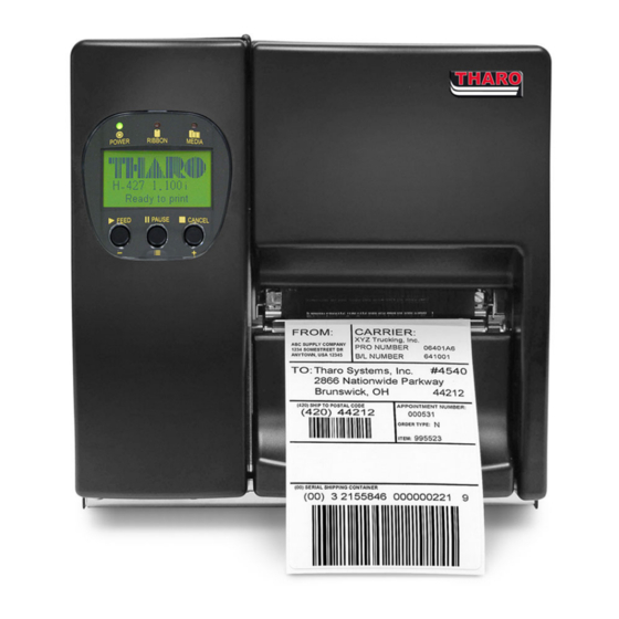
Page 6: Product Description
450 meter length ribbon capacities for large volume throughput. The THARO H-427 and H-436 feature a large, backlit LCD that is easy to read and is capable of displaying either text or graphics, making operation easy. A Real-Time Clock for time and date stamping of labels is standard on the H-427 and H-436. -
Page 7: Printer Options
This will allow you to input variable data to a label format stored in Flash memory or on the CompactFlash memory card. Ethernet Adapter The Internal Ethernet Adapter Card provides networking capability to the H-400 Series and H-600 Series Printers. Applicator Interface The applicator interface provides a means of communications between an applicator and the H-400 Series and H-600 Series Printers. -
Page 8: Technical Specifications
Type: Ink inside or ink outside thermal transfer ribbons (wax, resin and Ribbon wax/resin) in widths of 30 to 110mm (1.18” to 4.33”). Core inner diameter 25.4mm (1”). Maximum ribbon roll diameter 76mm (2.99”). Printer Language TPL (Tharo Programming Language) ® EASYLABEL Start... - Page 9 Type: Ink inside or ink outside thermal transfer ribbons (wax, resin and Ribbon wax/resin) in widths of 60 to 174mm (2.36” to 6.85”). Core inner diameter 25.4mm (1”). Maximum ribbon roll diameter 76mm (2.99”). Printer Language TPL (Tharo Programming Language) ® EASYLABEL Start Software Microsoft Windows Drivers, CUPS (Common UNIX Printing System) Driver 11 resident alphanumeric fonts (including OCR A &...
-
Page 10: General Safety Tips
2. General Safety Tips CAUTION! During the print process the Printhead will become hot. Do NOT attempt to clean the Printhead until it has had time to cool. The Printhead is the Most Fragile part of your Printer. Do NOT use sharp or hard objects to clean the Printhead. -
Page 11: Identifying Components
4. Identifying Components Control panel Bottom Front Cover Media Window Top Cover Fan-Fold Label Slot CF Card Slot Parallel Port Serial Port PS/2 Port USB Port Power Switch Power Socket Fan-Fold Label Slot - 10 -... - Page 12 Ribbon Rewind Shaft Ribbon Supply Shaft Printer Mechanism Platen Tear off Bar Printhead Lever Sensor Knob Label Guide Label Tension Plate Label Roll Bar Label Supply Guide Label Alignment Guide Movable sensor - 11 -...
- Page 13 MEDIA LED RIBBON LED POWER LED CANCEL Key PAUSE Key FEED Key MINUS (-) Key (Setting Mode) MENU Key (Setting Mode) PLUS (+) Key (Setting Mode) - 12 -...
-
Page 14: Printer Setup
5. Printer Setup CAUTION! When choosing a location for the Printer, ensure that the Printer and operator remain dry. If the Printer or the operator get wet, serious injury to the operator or damage to the Printer may occur. CAUTION! Make sure that the Printer’s power switch is in the “O”... -
Page 15: Usb Installation
Note: These instructions are only for use when using Windows Drivers. When using label software such as EASYLABEL® you can disable the prompting for Windows Drivers. Consult the knowledgebase on our website at www.tharo.com for detailed instructions. - 14 -... -
Page 16: Control Panel
6. Control Panel General Description and Operation Control keys FEED PAUSE CANCEL LED indicators Power on or ‘Ready’ POWER indicator RIBBON Ribbon status indicator MEDIA Media status indicator FEED Key After pressing the FEED Key, the printer will feed the media (according to media type) to the specified stop position. -
Page 17: Setting Mode
Using combinations of FEED, PAUSE, and CANCEL Keys, the printer can perform various functions as follows: Item Beep LCD Message Description Press and hold the FEED Key while turning on the printer Self Test Wait for Self-Test until the printer beeps 3 + Power on beeps times. -
Page 18: Menu Items And Available Options In Setting Mode
For Menu Items that are a list of selectable options, first line indicates the current item and the second line indicates current setting. Press the FEED/ENTER Key to select the displayed value for this Menu Item. Press the PAUSE/NEXT Key to move to the next available selection for this Menu Item. - Page 19 Default: Option OFF Strip Mode: turns the Stripper Sensor on. Option Setup Cutter Mode: turns the Cutter on. Applicator: Sets printer to be used with an applicator or foot switch. None: no options are attached. Default: Gap paper Gap: for labels with liner and gap, or hang tags. Sensor Setup Black Mark: for label or plain paper with black mark on the back.
- Page 20 Default: ON ON: The printer will sound the buzzer (beep) as a confirmation of Buzzer Setup most events. OFF: The printer will only sound the buzzer (beep) when there is a condition that requires the operator’s attention. Default: OFF When in stripper, applicator, or cutter mode, a label is printed and moved forward to be peeled off, taken by applicator or cut.
-
Page 21: Diagram Of The Setting Mode Menu
Diagram of the Setting Mode Menu - 20 -... -
Page 22: Loading Media
7. Loading Media Ribbon Installation 1. Open the Printer’s top cover. Pull the Printhead Lever out and rotate it upward to the right (counterclockwise) to open the Thermal Printhead. 3. Place the new ribbon roll onto the Ribbon Supply Shaft and place the empty ribbon core onto the Ribbon Rewind Shaft. -
Page 23: Label Installation
Label Installation 1. Open the Printer’s top cover. 2. Pull the Printhead Lever out and rotate it upward to the right (counterclockwise) to open the Printhead. 3. Pull the Label Alignment Guide in the direction as the blue arrow 1 indicates. - Page 24 7. Feed the label stock as shown. 8. Feed the label stock through under the Moveable Sensor and feed it to the Tear Bar. 9. Position the edge of the label stock against the Printer’s center wall and then position the Label Guide against the outside edge of the label stock.
-
Page 25: Activating The Stripper Sensor
Activating the Stripper Sensor The Stripper Sensor senses the presence of printed labels. With the Stripper Sensor activated, it is possible to operate the Printer in Tear-Off or Peel-Off (Strip-and-Peel) modes. See the “H-400 Internal Rewind Module Installation Instructions” section in this manual for more information about setting the Printer up for Strip-and-Peel. -
Page 26: Installing The Printer S Optional Accessories
8. Installing the Printer’s Optional Accessories Many of the Optional Accessories for the H-400/H-600 Series Printers can be easily installed and configured in the field using only a Number 2 Phillips screwdriver. This section will provide a component list and installation instructions for these optional accessories. CAUTION! Make sure that the Printer’s power switch is in the “O”... - Page 27 Remove the Rewind Module Cover Plate. Remove the U Shaped Metal Clip (1) from the rewind shaft and then install the Internal Rewind module using the 4 supplied screws (2). After installing the Internal Rewind Module, plug the cable connector onto the rewind control socket.
-
Page 28: H-400 Series Strip-And-Peel Setup
The Rewind Module Installation is complete. H-400 Series Strip-and-Peel Setup Face the front of the printer and remove the Bottom Cover Screw. Remove the Bottom Front Cover. Note: Removing bottom cover is not mandatory but may make installation easier. Pull the Printhead... - Page 29 Peel off several labels to expose about 400mm (16”) of liner. Then feed the liner between the Tear-Off Bar and the Bottom Front Cover. Wrap the liner around the Rewind Module (1), and use the U Shaped Metal Clip (2) to secure the liner.
-
Page 30: H-600 Series Stripper Module Installation
H-600 Series Stripper Module Installation Stripper sensor Module Locks Screws Face the front of the printer and remove the Bottom Cover Screw. Remove the Bottom Front Cover. Remove the two screws in the front of the printer to remove the Tear Off Bar. - 29 -... - Page 31 Secure the Stripper Module to the printer. Plug the stripper cable into the stripper connector at the bottom of the Rewind Module. Insert the cable into the locks. Peel the backing off the locks and then secure them to the bottom plate. Pull the Printhead lever out and rotate it upward to the right.
- Page 32 10. Peel off several labels to expose about 400mm (16”) of liner. Then feed the liner through the Stripper Module. 11. Close the Stripper Module and secure the lock bar. 12. Wrap the liner around the Rewind Module (1), and use the U Shaped Metal Clip (2) to secure the liner.
-
Page 33: Rewind Bracket Installation And Use
Rewind Bracket Installation and Use Face the front of the Printer and remove the Bottom Cover Screw. Remove the Bottom Front Cover. Mount the Label Rewind Bracket onto the Printhead Mechanism and secure with the screws provided. The Label Rewind Bracket is now installed. -
Page 34: Cutter Installation
Cutter Installation (H-400 Series is shown the H-600 is similar) Cutter Cover Cutter Locks Screws Face the front of the Printer and remove the Bottom Cover Screw. Remove the Bottom Front Cover. Remove the two screws in the front of the Printer to remove the Tear Off Bar. - Page 35 Secure the Cutter to the Printer with two screws. Plug the Cutter cable into the cutter connector on the center wall. Insert the cable into the locks. Peel the backing off the locks and then secure them to the bottom plate Hang the Cutter Cover on the Cutter and then tighten the...
-
Page 36: Using The Printer With Aps/2 Keyboard
9. Using the Printer with a PS/2 Keyboard Entering/Exiting Keyboard Mode NOTICE! The location of keys on a keyboard can vary based on the language! Before connecting a keyboard please set the correct Keyboard Language in Setup. (See the section ‘Menu items and available Options in Setting Mode’.) The PS/2 interface can be used to connect a keyboard to the Printer for stand-alone printing without a computer attached. -
Page 37: Menu Items And Options Available In Keyboard Mode
Menu Items and Options available in Keyboard Mode Once the Printer is in Keyboard Mode, the user will be presented with a menu. The user can navigate through the menu by using the Up and Down arrow keys on the keyboard. Menu selections are made by pressing the Enter key on the keyboard while the item is displayed. -
Page 38: Downloading To The Flash Memory Using Easylabel
Downloading to the Flash Memory using EASYLABEL EASYLABEL formats can be downloaded to the Printer’s Flash Memory (or CompactFlash card) and the user will be able to print labels from the Printer without a PC attached. NOTICE! The “Use Memory Card” Printer Configuration option in EASYLABEL determines if the Printer’s Flash memory or a CompactFlash card is used to store formats. -
Page 39: Appendix A. Communication Interfaces
Appendix A. Communication Interfaces Parallel Interface The Printers are equipped with a 36-pin Parallel interface connector. Any standard IBM PC compatible parallel cable can be used to connect to your Printer. In the event of any difficulties, the table listed below can be used to obtain a suitable cable. PIN NO. -
Page 40: Usb Interface
USB Interface The Printer is equipped with a Type B USB connector that can be connected to any compatible USB port. PIN NO. FUNCTION USBVCC PS/2 Interface The PS/2 interface can be used to connect a keyboard to the Printer for stand-alone printing without a computer attached. -
Page 41: Appendix B. Error Messages / Troubleshooting
Appendix B. Error Messages / Troubleshooting Self-Test The Self-Test function in the Printer will help the user to troubleshoot whether the Printer is operating normally. In the Self-Test Mode, the Printer will print out a test sample each time the FEED Key is pressed. -
Page 42: Lcd Error Messages And Descriptions
LCD Error Messages and Descriptions Blinking Blinking Steady Quickly Slowly LED Lights Beep Description Solution Message Ribbon Media Printhead is The Printhead not firmly Re-open the Printhead and opened locked in place. make sure it closes tightly. Entering the Printhead temperature is Printer goes back to standby Cooling Process too high. -
Page 43: Problems And Recommended Solutions
Problems and Recommended Solutions Problem Recommended Solution LCD shows no message after Check the power cord. switching the Printer on. LED light turns red Check for software setting or program command errors. (power/status) after printing Check if labels or ribbon is out and replace with suitable stops. -
Page 44: Appendix C. Maintenance And Adjustment
Appendix C. Maintenance and Adjustment Thermal Printhead Cleaning CAUTION! The Printhead is the Most Fragile part of your Printer. Do NOT use sharp or hard objects to clean the Printhead. Do NOT touch the glass surface of the Printhead with your hand. CAUTION! During the print process the Printhead will become hot. -
Page 45: Printhead Module Installation / Removal Instructions
Printhead Module Installation / Removal Instructions Switch the Printer off and unplug it. Pull the Printhead Lever out and rotate it upward to the right (counterclockwise) to open the Printhead. Gently pull the Printhead assembly towards you. To replace the Printhead, line up the plug and side guides of the... -
Page 46: Printhead Print Line Adjustment
Printhead Print Line Adjustment When printing on stiff or thick paper, the Print Line needs to be moved forward (paper feed direction) in order to achieve better print quality. Open the Top Cover. Pull the Printhead Lever out and rotate it upward to the right (counterclockwise) to open the Printhead. -
Page 47: Thermal Printhead Balance Adjustment
Thermal Printhead Balance Adjustment If one side of the printed labels is not being printed clearly, or if ribbon wrinkles occur, then adjust the Thermal Printhead Spring Box position to cure the problem. Pull the Printhead Lever out H – 400 Series and rotate it upward to the right (counterclockwise) to open the Printhead. -
Page 48: Ribbon Shield Adjustment
Ribbon Shield Adjustment If ribbon wrinkle occurs during printing, adjust the ribbon shield. Example: If ribbon wrinkle occurs as shown in figure (a), please turn the ribbon shield screw A clockwise, and if ribbon wrinkle occurs as shown in figure (b), please turn the ribbon shield screw B clockwise. -
Page 49: Auto Sensing
Auto Sensing Using Auto Sensing the Printer automatically detects and records the label type and length (gap or black mark paper). Then the Printer can accurately detect the label positions. 1. Adjust the Moveable Sensor so that it is located in a position to sense the label gaps or black marks. -
Page 50: Downloading True Type Fonts To The Printer's Flash Memory
6. After the “Open” button is clicked, the firmware download process will start immediately. A blue progress bar will pop up to display the progress of download. 7. When the progress bar reaches “100%”, the firmware download is complete. As the download finishes, the Ribbon and Media light will alternately flash slowly and then rapidly. - Page 51 4. After the “Open” button is clicked, the download process will start immediately. A blue progress bar will pop up to display the progress of the download. 5. When the progress bar reaches “100%”, the TrueType Font download is complete and the TrueType Font is stored in the Printer’s Flash memory.
-
Page 52: Clearing Cutter Jams On The H-400 Series Cutter
Clearing Cutter Jams on the H-400 Series Cutter 1. If the Cutter jams or malfunctions turn the Printer Off. 2. There is a hole (marked “A”) on each side of the Cutter. Insert a 3mm hex key into one of these holes and use the key to turn the cutter blade clockwise.
Need help?
Do you have a question about the H-400 Series and is the answer not in the manual?
Questions and answers