Table of Contents
Advertisement
Advertisement
Table of Contents

Related Manuals for Tharo Systems H-426


Summary of Contents for Tharo Systems H-426
- Page 1 THARO H-Series Users Manual P/N. 920-011211-01 Edition 6 June 2004...
- Page 2 Dispose of used batteries according to the manufacturer’s instructions. Copyright and Trademark Notice © 2005 by Tharo Systems, Inc. It is illegal to photocopy or electronically transmit a facsimile of this manual or any portion of its contents for any means or purpose without the publisher’s permission. Fines of up to $10,000.00 may be imposed for violation.
-
Page 3: Table Of Contents
TABLE OF CONTENTS 1. P ..................5 RODUCT ESCRIPTION General Information ......................... 5 Printer Options............................ 5 Technical Specifications ........................6 2. G ................... 7 ENERAL AFETY 3. U ..........7 NPACKING THE RINTER AND CCESSORIES 4. I .................. 8 DENTIFYING OMPONENTS 5. - Page 4 A. C ............26 PPENDIX OMMUNICATION NTERFACES Parallel Interface..........................26 Serial Interface..........................26 USB Interface............................ 27 Installation of the USB HS Serial Converter ................. 27 Removing the USB HS Serial Converter................. 29 PS/2 Interface........................... 29 B. E ........30 PPENDIX RROR ESSAGES ROUBLESHOOTING...
-
Page 5: Warranty Information
LABOR FOR THE REPAIR OR REPLACEMENT OF PRODUCTS FOUND TO BE DEFECTIVE IN MATERIAL OR WORKMANSHIP DURING THE WARRANTY PERIOD. As a condition of this warranty, the user must: (a) obtain a THARO Return Authorization for the printer, or subassembly(s);... -
Page 6: Product Description
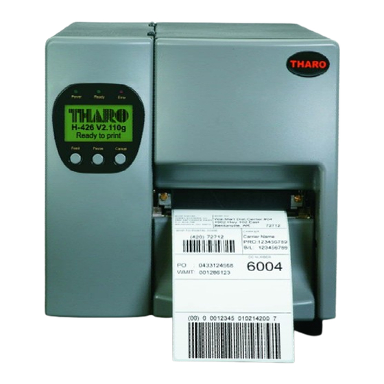
Printers are designed to be durable, tough and reliable, even in the harshest environments. The THARO H-426 features a printhead density of 8 dots/mm (203 dots/in) and a maximum print length of 1270mm (50”). -
Page 7: Technical Specifications
Length: 450m (1471’) Ribbon Width: 30mm (1.18”) ~ 110mm (4.33”) Inner Core Diameter: 25.4mm (1”) Ribbon Roll Diameter: 75mm (2.95”) Printer Language TPL (Tharo Programming Language) ® Application: EASYLABEL Start Software Driver: Microsoft Windows 95, 98, ME, NT 4, 2000 and XP 9 resident alphanumeric fonts (including OCR A &... -
Page 8: General Safety Tips
2. General Safety Tips CAUTION! During the print process the printhead will become hot. Do NOT attempt to clean the printhead until it has had time to cool. The Printhead is the Most Fragile part of your Printer. Do NOT use sharp or hard objects to clean the Printhead. -
Page 9: Identifying Components
4. Identifying Components Top Cover Label Width Guide Ribbon Feed Rod Indicator Light Ink Position Lever Label Feed Rods Liquid Crystal Display Printhead Spring Box Label Feed Guide (LCD) Control Keys Stripper Sensor Fan-Fold Label Slot Ribbon Rod Tear-Off Bar Power Socket Bottom Front Cover Printer Mechanism... - Page 10 Moveable Sensor Lever Sensor Position Mark Moveable Sensor - 9 -...
-
Page 11: Printer Setup
5. Printer Setup CAUTION! When choosing a location for the Printer, ensure that the Printer and operator remain dry. If the Printer or the operator get wet, serious injury to the operator or damage to the Printer may occur. CAUTION! Make sure that the Printer’s power switch is in the “O”... -
Page 12: Control Panel
6. Control Panel General Description and Operation Pause Key Pressing the Pause key when the Printer is in Standby Mode will put the Printer in Pause Mode and the LCD will display “H-xxx Hx.xxx Pause”. When the Printer is in Pause it will not receive any commands. -
Page 13: Menu Items And Available Options In Setting Mode
Menu items and available options in Setting Mode NOTICE! “Default Setting” is the value of the setting as delivered from the factory. Any changes made in Setup Mode are saved after the Printer is turned off. Thermal Transfer: when printing, a ribbon must be installed to transfer the print contents onto the media. - Page 14 When in stripper or cut mode, a label is printed and moved forward to be cut or peeled off. If Smart Backfeed is ON, the next label will be partially printed so the printer does not have to backfeed to find the original starting point Smart Backfeed when printing continues.
-
Page 15: Interpreting Lcd/Led Messages
Interpreting LCD/LED Messages LED Light Beep Description Display Power Ready Error Model Name H-xxx: Printer model; Hx.xxx: current firmware Green Green Hx.xxx version. Printer is in Self-Test Mode. Refer to Appendix B Self-Test Green Green for more information. Now in Printer is in Dump Mode. -
Page 16: Loading Media
7. Loading Media Ribbon Out If the ribbon runs out during a print job, the Printer will beep four times and the Red error light will glow. An “Out of ribbon or check ribbon sensor” message will be displayed on the Printer’s front panel. - Page 17 7. Wrap the ribbon around the Ribbon Shaft Rod making sure that the ribbon rewind direction is correct. 8. Ribbon outside (ink outside the roll). 9. Ribbon inside (ink inside the roll). 10. Attach the end of the ribbon to the empty ribbon core using adhesive tape or part of a label.
-
Page 18: Label Installation
Label Installation 1. Open the Printer’s top cover. 2. Slide the roll of label stock onto the Label Roll Bar all the way back to the Printer’s inner wall. 3. Slide the Label Width Guide in until it rests against the label stock. Avoid pushing the guide in too far or you will damage the edge of the label stock. -
Page 19: Activating The Stripper Sensor
The Stripper Sensor senses the presence of printed labels. With the Stripper Sensor activated, it is possible to operate the Printer in Tear-Off or Peel-Off (Strip-and-Peel) modes. See the “THARO H- Series Internal Rewind Module Installation Instructions” section in this manual for more information about setting the Printer up for Strip-and-Peel. -
Page 20: Installing The Printer S Optional Accessories
Unplug the power cord from the Printer before performing any service on it. Failure to do so could result in personal injury or damage to the Printer! THARO H-Series Internal Rewind Module Components Internal Rewind Module U-Shaped Metal Clip Screws (M3X4.5) Qty. 4 NOTICE! The Internal Rewind must be used with the Stripper Sensor. -
Page 21: Internal Rewind Module Installation Instructions
THARO H-Series Internal Rewind Module Installation Instructions 1. Open the Top Cover of the Printer and turn the Printer sideways. 2. Remove the 2 screws (E) for the rewind cover and then remove the rewind cover (C). 3. Remove the U Shape Metal Clip (2) -
Page 22: Cutter Module Components
2. Cutter Module and connector 3. Screws (M3X8), Qty. 2 4. Tray 5. Wire Saddles, Qty. 2 THARO H-Series Cutter Module Installation Instructions 1. Face the front of the Printer and unscrew the Bottom Cover Screw (A). Carefully remove the Bottom Front Cover (B) DO NOT pull the cover with full force. - Page 23 4. Plug the connector cable into the Cutter control socket (D). 5. Place the Cutter cable into the Wire Saddles (6), and insert the Wire Saddles into the holes. 6. Position the Cutter Cover (1) over the Cutter Module, and use the Bottom Cover Screw (A) to secure the cover into place.
-
Page 24: Using The Printer With Aps/2 Keyboard
9. Using the Printer with a PS/2 Keyboard Entering/Exiting Keyboard Mode NOTICE! The location of keys on a keyboard can vary based on the language! Before connecting a keyboard please set the correct Keyboard Language in Setup. (See the section ‘Menu items and available Options in Setting Mode’.) The PS/2 interface can be used to connect a keyboard to the Printer for stand-alone printing without a computer attached. -
Page 25: Menu Items And Options Available In Keyboard Mode
Menu Items and Options available in Keyboard Mode Once the Printer is in Keyboard Mode, the user will be presented with a menu. The user can navigate through the menu by using the Up and Down arrow keys on the keyboard. Menu selections are made by pressing the Enter key on the keyboard while the item is selected. - Page 26 Downloading to Flash Memory using EASYLABEL EASYLABEL formats can be downloaded to the H-Series printer’s flash memory where the user will be able to print labels from the H-Series printer without a PC attached. When creating a format in EASYLABEL, be sure the Memory Card Download option in the Format Specifications page is set to YES.
-
Page 27: Appendix A. Communication Interfaces
Appendix A. Communication Interfaces Parallel Interface The Printers are equipped with a 36-pin Parallel interface connector. Any standard IBM PC compatible parallel cable can be used to connect to your Printer. In the event of any difficulties, the table listed below can be used to obtain a suitable cable. PIN NO. -
Page 28: Usb Interface
USB Interface The Printer is equipped with a Type B USB connector that can be connected to any compatible USB port. PIN NO. USBVC FUNCTION Installation of the USB HS Serial Converter 1. USB is a Plug & Play facility. Once the USB cable is connected from the PC to the Printer, the PC will automatically detect the new device and begin the... - Page 29 3. Select “Specify a location” as the location of the driver. (the drivers are in the USB_Serial Converter Drivers directory on the CD). click “Next”. Once the USB device driver is located click “Next”. The driver will be installed and the wizard will close. This USB device driver uses a virtual COM port that redirects any data sent to it out of the PC’s USB port.
-
Page 30: Removing The Usb Hs Serial Converter
Removing the USB HS Serial Converter To remove the USB device driver, go to the Windows Control Panel and double click the Add/Remove Programs icon. Click on FTDI USB to Serial Converter Drivers in the program list and click the Add/Remove button. -
Page 31: Appendix B. Error Messages / Troubleshooting
Appendix B. Error Messages / Troubleshooting Self Test The Printer’s Self Test function prints a Test Label every time the Feed Key is pressed. The Test Label consists of a test pattern and a variety of information about how the Printer is configured as well as its status. -
Page 32: Lcd Error And Led Light Message Descriptions
LCD Error and LED Light Message Descriptions LED Message Light Beeps Description Solution Message Power Ready Error Display The Printhead is Printhead is Re-open the Printhead and make Green not firmly in opened sure it closes tightly. place. Entering the Printhead Printer goes back to standby Cooling... -
Page 33: Problems And Recommended Solutions
Problems and Recommended Solutions Problem Recommended Solution LCD shows no message after Check the power cord switching the Printer on LED light turns red Check for software setting or program command errors (power/status) after printing Check if labels or ribbon is out and replace with suitable stops labels or ribbon Check if label stock is jammed... -
Page 34: Appendix C. Maintenance And Adjustment
Appendix C. Maintenance and Adjustment Cleaning the Thermal Printhead CAUTION! The Printhead is the Most Fragile part of your Printer. Do NOT use sharp or hard objects to clean the Printhead. Do NOT touch the glass surface of the Printhead with your hand. CAUTION! During the print process the Printhead will become hot. -
Page 35: Thermal Printhead Replacement
Thermal Printhead Replacement 1. Switch the power off to the printer and unplug the printer. 2. Pull the Printhead Lever rotate upward to the right to open Printhead. Remove media from the printer. 3. Gently pull printhead assembly towards you as shown. 4. -
Page 36: Thermal Printhead Print Line Adjustment
Thermal Printhead Print Line Adjustment When printing on stiff or thick paper, the Print Line needs to be moved forward (paper feed direction) in order to achieve better print quality. 1. Pull the Printhead Lever out and rotate it upward to the right (counterclockwise) to open the... - Page 37 3. Move the Print Line all the way back by turning the screws on each side of the Printhead (marked B) counterclockwise 4. Then turn the screws clockwise a quarter turn at a time to move the Print Line forward. Adjust both screws by the same amount to ensure...
-
Page 38: Thermal Printhead Spring Box Position/Pressure Adjustment
Thermal Printhead Spring Box Position/Pressure Adjustment If one side of the printed labels is not being printed clearly, or if ribbon wrinkles occur, then adjust the Thermal Printhead Spring Box position or pressure to cure the problem. 1. Pull the Printhead Lever out and rotate it upward to the right (counterclockwise) to open the Printhead. -
Page 39: Drive Roller Replacement
Drive Roller Replacement 1. Switch the power off to the printer and unplug the printer. 2. Pull the Printhead Lever out and rotate it upward to the right (counterclockwise) to open the Printhead. 3. Remove all six Phillips screws (white arrows) and the c-clip (red arrow) as shown. - Page 40 5. Remove the c-clip (orange arrow), two gears (green arrows) and two belts (yellow arrows) as shown. 6. You may now remove the drive roller from the media side of the printer. Reverse these steps to re-install the drive roller. - 39 -...
-
Page 41: Auto Sensing
Auto Sensing Using Auto Sensing the Printer automatically detects and records the label type and length (gap or black mark paper). Then the Printer can accurately detect the label positions. 1. Adjust the Moveable Sensor so that it is located in a position to sense the label gaps or black marks. -
Page 42: Cleaning Adhesive From The Cutter Blade
Cleaning Adhesive from the Cutter Blade When using adhesive labels, the cutter may malfunction due to a build up of adhesive on the blade. When this happens it will be necessary to clean the Cutter Blade: 1. Turn the Printer Off. 2.
Need help?
Do you have a question about the H-426 and is the answer not in the manual?
Questions and answers